Transcription
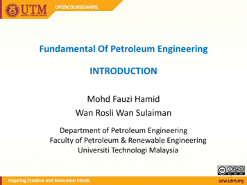
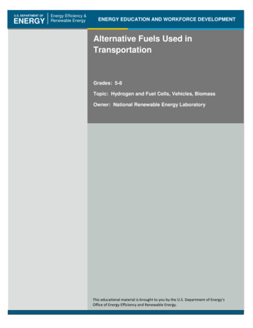
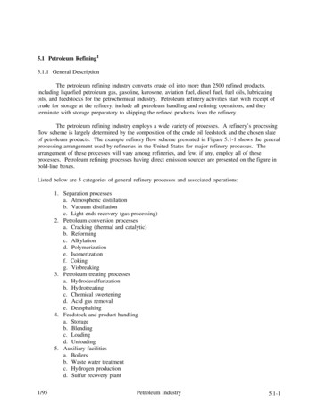
5.1 Petroleum Refining15.1.1 General DescriptionThe petroleum refining industry converts crude oil into more than 2500 refined products,including liquefied petroleum gas, gasoline, kerosene, aviation fuel, diesel fuel, fuel oils, lubricatingoils, and feedstocks for the petrochemical industry. Petroleum refinery activities start with receipt ofcrude for storage at the refinery, include all petroleum handling and refining operations, and theyterminate with storage preparatory to shipping the refined products from the refinery.The petroleum refining industry employs a wide variety of processes. A refinery’s processingflow scheme is largely determined by the composition of the crude oil feedstock and the chosen slateof petroleum products. The example refinery flow scheme presented in Figure 5.1-1 shows the generalprocessing arrangement used by refineries in the United States for major refinery processes. Thearrangement of these processes will vary among refineries, and few, if any, employ all of theseprocesses. Petroleum refining processes having direct emission sources are presented on the figure inbold-line boxes.Listed below are 5 categories of general refinery processes and associated operations:1. Separation processesa. Atmospheric distillationb. Vacuum distillationc. Light ends recovery (gas processing)2. Petroleum conversion processesa. Cracking (thermal and catalytic)b. Reformingc. Alkylationd. Polymerizatione. Isomerizationf. Cokingg. Visbreaking3. Petroleum treating processesa. Hydrodesulfurizationb. Hydrotreatingc. Chemical sweeteningd. Acid gas removale. Deasphalting4. Feedstock and product handlinga. Storageb. Blendingc. Loadingd. Unloading5. Auxiliary facilitiesa. Boilersb. Waste water treatmentc. Hydrogen productiond. Sulfur recovery plant1/95Petroleum Industry5.1-1
5.1-2EMISSION FACTORS1/95Figure 5.1-1. Schematic of an example integrated petroleum refinery.
e. Cooling towersf. Blowdown systemg. Compressor enginesThese refinery processes are defined below, and their emission characteristics and applicable emissioncontrol technology are discussed.5.1.1.1 Separation Processes The first phase in petroleum refining operations is the separation of crude oil into its majorconstituents using 3 petroleum separation processes: atmospheric distillation, vacuum distillation, andlight ends recovery (gas processing). Crude oil consists of a mixture of hydrocarbon compoundsincluding paraffinic, naphthenic, and aromatic hydrocarbons with small amounts of impuritiesincluding sulfur, nitrogen, oxygen, and metals. Refinery separation processes separate these crude oilconstituents into common boiling-point fractions.5.1.1.2 Conversion Processes To meet the demands for high-octane gasoline, jet fuel, and diesel fuel, components such asresidual oils, fuel oils, and light ends are converted to gasolines and other light fractions. Cracking,coking, and visbreaking processes are used to break large petroleum molecules into smaller ones.Polymerization and alkylation processes are used to combine small petroleum molecules into largerones. Isomerization and reforming processes are applied to rearrange the structure of petroleummolecules to produce higher-value molecules of a similar molecular size.5.1.1.3 Treating Processes Petroleum treating processes stabilize and upgrade petroleum products by separating them fromless desirable products and by removing objectionable elements. Undesirable elements such as sulfur,nitrogen, and oxygen are removed by hydrodesulfurization, hydrotreating, chemical sweetening, andacid gas removal. Treating processes, employed primarily for the separation of petroleum products,include such processes as deasphalting. Desalting is used to remove salt, minerals, grit, and waterfrom crude oil feedstocks before refining. Asphalt blowing is used for polymerizing and stabilizingasphalt to improve its weathering characteristics.5.1.1.4 Feedstock And Product Handling The refinery feedstock and product handling operations consist of unloading, storage, blending,and loading activities.5.1.1.5 Auxiliary Facilities A wide assortment of processes and equipment not directly involved in the refining of crudeoil is used in functions vital to the operation of the refinery. Examples are boilers, waste watertreatment facilities, hydrogen plants, cooling towers, and sulfur recovery units. Products fromauxiliary facilities (clean water, steam, and process heat) are required by most process units throughoutthe refinery.5.1.2 Process Emission Sources And Control TechnologyThis section presents descriptions of those refining processes that are significant air pollutantcontributors. Process flow schemes, emission characteristics, and emission control technology arediscussed for each process. Table 5.1-1 lists the emission factors for direct-process emissions in1/95Petroleum Industry5.1-3
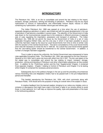
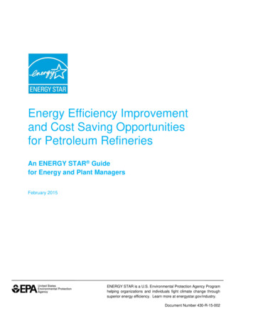
5.1-4Table 5.1-1 (Metric And English Units). EMISSION FACTORS FOR PETROLEUM REFINERIESaProcessParticulateSulfur Oxides(as SO2)CarbonMonoxideTotalHydrocarbonsbNitrogen Oxides(as Boilers and process heatersFuel oilSee Section 1.3 - "Fuel Oil Combustion"Natural gasSee Section 1.4 - "Natural Gas Combustion"Fluid catalytic cracking units(FCC)cUncontrolledkg/103 L fresh feed0.695EMISSION FACTORS(0.267 to 0.976)lb/103 bbl fresh feed242(93 to 340)1.41339.20.630(0.286 to 1.505)4930.204B(0.107 to 0.416)13,700220(100 to 525)71.01954BNegNegBNegNegB(37.1 to 145.0)Electrostatic precipitatorand CO boilerkg/103 L fresh feed0.128d(0.020 to 0.428)lb/103 bbl fresh feed45d(7 to 150)1.413NegNeg(0.286 to 1.505)4930.204e(0.107 to 0.416)NegNeg(100 to 525)71.0e(37.1 to 145.0)Moving-bed catalyticcracking unitsfkg/103 L fresh feedlb/103 bbl fresh feedFluid coking 3 L fresh feed3lb/10 bbl fresh feed1.50523Electrostatic precipitatorand CO boiler1/95kg/103 L fresh feed0.0196NDNegNegNDNegNegClb/103 bbl fresh feed6.85NDNegNegNDNegNegC
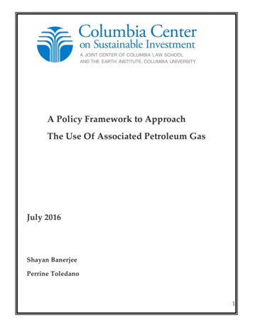
1/95Table 5.1-1 (cont.).ProcessParticulateDelayed coking unitsSulfur Oxides(as SO2)CarbonMonoxideTotalHydrocarbonsbNitrogen Oxides(as 03 L refinery feedNegNegNeg1,662NegNegNegClb/103 bbl refinery egCNegNegNegCNegNegNegCNegNegNegChCompressor enginesReciprocating engineskg/103 m3 gas burned33lb/10 ft gas burnedGas turbineskg/103 m3 gas burned33lb/10 ft gas burnedPetroleum IndustryBlowdown systemskUncontrolledVapor recovery systemand flaringkg/103 L refinery feed3lb/10 bbl refinery feedNeg26.90.0120.0024.30.818.9Vacuum distillationcolumn condensersmUncontrolledkg/103 L vacuum feedNegNegNeg0.14(0 to 0.37)lb/103 bbl vacuum feedNegNegNegControlled (vented to heateror incinerator)NegNegNeg50(0 to 130)Neg5.1-5
5.1-6Table 5.1-1 (cont.).ProcessClaus plant and tail gastreatmentabcdParticulateSulfur Oxides(as SO2)CarbonMonoxideTotalHydrocarbonsbNitrogen Oxides(as NO2)AldehydesAmmoniaEMISSIONFACTORRATINGSee Section 8.13 - "Sulfur Recovery"EMISSION FACTORSNumbers in parentheses indicate range of values observed. Neg negligible. ND no data.Overall, less than 1 weight % of total hydrocarbon emissions is methane.References 2-8.Under the New Source Performance Standards, controlled FCC regenerators must have particulate emissions lower than 0.054 kg/103 L(19 lb/103 bbl) fresh feed.e May be higher, from the combustion of ammonia.g Reference 2.g Reference 5.h References 9-10.j Based on 100% combustion of sulfur to SO . s refinery gas sulfur content (in kg/1000 m3 or lb/1000 ft3, depending on desired units for2emission factor).k References 2,11.m References 2,12-13. If refinery feed rate is known, rather than vacuum feed rate, assume vacuum feed is 36% of refinery feed. Refineryfeed rate is defined as the crude oil feed rate to the atmospheric distillation column.1/95
petroleum refineries. Factors are expressed in units of kilograms per 1000 liters (kg/103 L) orkilograms per 1000 cubic meters (kg/103 m3) and pounds per 1000 barrels (lb/103 bbl) or pounds per1000 cubic feet (lb/103 ft3). The following process emission sources are discussed here:1.2.3.4.5.6.7.8.Vacuum distillationCatalytic crackingThermal cracking processesUtility boilersHeatersCompressor enginesBlowdown systemsSulfur recovery5.1.2.1 Vacuum Distillation Topped crude withdrawn from the bottom of the atmospheric distillation column is composedof high boiling-point hydrocarbons. When distilled at atmospheric pressures, the crude oil decomposesand polymerizes and will foul equipment. To separate topped crude into components, it must bedistilled in a vacuum column at a very low pressure and in a steam atmosphere.In the vacuum distillation unit, topped crude is heated with a process heater to temperaturesranging from 370 to 425 C (700 to 800 F). The heated topped crude is flashed into a multitrayvacuum distillation column operating at absolute pressures ranging from 350 to 1400 kilograms persquare meter (kg/m2) (0.5 to 2 pounds per square inch absolute [psia]). In the vacuum column, thetopped crude is separated into common boiling-point fractions by vaporization and condensation.Stripping steam is normally injected into the bottom of the vacuum distillation column to assist theseparation by lowering the effective partial pressures of the components. Standard petroleum fractionswithdrawn from the vacuum distillation column include lube distillates, vacuum oil, asphalt stocks, andresidual oils. The vacuum in the vacuum distillation column is usually maintained by the use of steamejectors but may be maintained by the use of vacuum pumps.The major sources of atmospheric emissions from the vacuum distillation column areassociated with the steam ejectors or vacuum pumps. A major portion of the vapors withdrawn fromthe column by the ejectors or pumps is recovered in condensers. Historically, the noncondensableportion of the vapors has been vented to the atmosphere from the condensers. There areapproximately 0.14 kg of noncondensable hydrocarbons per m3 (50 lb/103 bbl) of topped crudeprocessed in the vacuum distillation column.2,12-13 A second source of atmospheric emissions fromvacuum distillation columns is combustion products from the process heater. Process heaterrequirements for the vacuum distillation column are approximately 245 megajoules per cubic meter(MJ/m3) (37,000 British thermal units per barrel [Btu/bbl]) of topped crude processed in the vacuumcolumn. Process heater emissions and their control are discussed below. Fugitive hydrocarbonemissions from leaking seals and fittings are also associated with the vacuum distillation unit, butthese are minimized by the low operating pressures and low vapor pressures in the unit. Fugitiveemission sources are also discussed later.Control technology applicable to the noncondensable emissions vented from the vacuumejectors or pumps includes venting into blowdown systems or fuel gas systems, and incineration infurnaces or waste heat boilers.2,12-13 These control techniques are generally greater than 99 percentefficient in the control of hydrocarbon emissions, but they also contribute to the emission ofcombustion products.1/95Petroleum Industry5.1-7
5.1.2.2 Catalytic Cracking Catalytic cracking, using heat, pressure, and catalysts, converts heavy oils into lighter productswith product distributions favoring the more valuable gasoline and distillate blending components.Feedstocks are usually gas oils from atmospheric distillation, vacuum distillation, coking, anddeasphalting processes. These feedstocks typically have a boiling range of 340 to 540 C (650 to1000 F). All of the catalytic cracking processes in use today can be classified as either fluidized-bedor moving-bed units.5.1.2.2.1 Fluidized-bed Catalytic Cracking (FCC) The FCC process uses a catalyst in the form of very fine particles that act as a fluid whenaerated with a vapor. Fresh feed is preheated in a process heater and introduced into the bottom of avertical transfer line or riser with hot regenerated catalyst. The hot catalyst vaporizes the feed,bringing both to the desired reaction temperature, 470 to 525 C (880 to 980 F) The high activity ofmodern catalysts causes most of the cracking reactions to take place in the riser as the catalyst and oilmixture flows upward into the reactor. The hydrocarbon vapors are separated from the catalystparticles by cyclones in the reactor. The reaction products are sent to a fractionator for separation.The spent catalyst falls to the bottom of the reactor and is steam stripped as it exits the reactorbottom to remove absorbed hydrocarbons. The spent catalyst is then conveyed to a regenerator. Inthe regenerator, coke deposited on the catalyst as a result of the cracking reactions is burned off in acontrolled combustion process with preheated air. Regenerator temperature is usually 590 to 675 C(1100 to 1250 F). The catalyst is then recycled to be mixed with fresh hydrocarbon feed.5.1.2.2.2 Moving-bed Catalytic CrackingIn the moving-bed system, typified by the Thermafor Catalytic Cracking (TCC) units, catalystbeads ( 0.5 centimeters [cm] [0.2 inches (in.)]) flow into the top of the reactor, where they contact amixed-phase hydrocarbon feed. Cracking reactions take place as the catalyst and hydrocarbons moveconcurrently downward through the reactor to a zone where the catalyst is separated from the vapors.The gaseous reaction products flow out of the reactor to the fractionation section of the unit. Thecatalyst is steam stripped to remove any adsorbed hydrocarbons. It then falls into the regenerator,where coke is burned from the catalyst with air. The regenerated catalyst is separated from the fluegases and recycled to be mixed with fresh hydrocarbon feed. The operating temperatures of thereactor and regenerator in the TCC process are comparable to those in the FCC process.Air emissions from catalytic cracking processes are (1) combustion products from processheaters and (2) flue gas from catalyst regeneration. Emissions from process heaters are discussedbelow. Emissions from the catalyst regenerator include hydrocarbons, oxides of sulfur, ammonia,aldehydes, oxides of nitrogen, cyanides, carbon monoxide (CO), and particulates (Table 5.1-1). Theparticulate emissions from FCC units are much greater than those from TCC units because of thehigher catalyst circulation rates used.2-3,5FCC particulate emissions are controlled by cyclones and/or electrostatic precipitators.Particulate control efficiencies are as high as 80 to 85 percent.3,5 Carbon monoxide waste heat boilersreduce the CO and hydrocarbon emissions from FCC units to negligible levels.3 TCC catalystregeneration produces similar pollutants to FCC units, but in much smaller quantities (Table 5.1-1).The particulate emissions from a TCC unit are normally controlled by high-efficiency cyclones.Carbon monoxide and hydrocarbon emissions from a TCC unit are incinerated to negligible levels bypassing the flue gases through a process heater firebox or smoke plume burner. In some installations,sulfur oxides are removed by passing the regenerator flue gases through a water or causticscrubber.2-3,55.1-8EMISSION FACTORS1/95
5.1.2.3 Thermal Cracking Thermal cracking processes include visbreaking and coking, which break heavy oil moleculesby exposing them to high temperatures.5.1.2.3.1 Visbreaking Topped crude or vacuum residuals are heated and thermally cracked (455 to 480 C, 3.5 to 17.6kg/cm2 [850 to 900 F, 50 to 250 pounds per square inch gauge (psig)]) in the visbreaker furnace toreduce the viscosity, or pour point, of the charge. The cracked products are quenched with gas oil andflashed into a fractionator. The vapor overhead from the fractionator is separated into light distillateproducts. A heavy distillate recovered from the fractionator liquid can be used as either a fuel oilblending component or catalytic cracking feed.5.1.2.3.2 Coking Coking is a thermal cracking process used to convert low value residual fuel oil to highervalue gas oil and petroleum coke. Vacuum residuals and thermal tars are cracked in the cokingprocess at high temperature and low pressure. Products are petroleum coke, gas oils, and lighterpetroleum stocks. Delayed coking is the most widely used process today, but fluid coking is expectedto become an important process in the future.In the delayed coking process, heated charge stock is fed into the bottom of a fractionator,where light ends are stripped from the feed. The stripped feed is then combined with recycle productsfrom the coke drum and rapidly heated in the coking heater to a temperature of 480 to 590 C (900 to1100 F). Steam injection is used to control the residence time in the heater. The vapor-liquid feedleaves the heater, passing to a coke drum where, with controlled residence time, pressure (1.8 to 2.1kg/cm2 [25 to 30 psig]), and temperature (400 C [750 F]), it is cracked to form coke and vapors.Vapors from the drum return to the fractionator, where the thermal cracking products are recovered.In the fluid coking process, typified by Flexicoking, residual oil feeds are injected into thereactor, where they are thermally cracked, yielding coke and a wide range of vapor products. Vaporsleave the reactor and are quenched in a scrubber, where entrained coke fines are removed. The vaporsare then fractionated. Coke from the reactor enters a heater and is devolatilized. The volatiles fromthe heater are treated for fines and sulfur removal to yield a particulate-free, low-sulfur fuel gas. Thedevolatilized coke is circulated from the heater to a gasifier where 95 percent of the reactor coke isgasified at high temperature with steam and air or oxygen. The gaseous products and coke from thegasifier are returned to the heater to supply heat for the devolatilization. These gases exit the heaterwith the heater volatiles through the same fines and sulfur removal processes.From available literature, it is unclear what emissions are released and where they are released.Air emissions from thermal cracking processes include coke dust from decoking operations,combustion gases from the visbreaking and coking process heaters, and fugitive emissions. Emissionsfrom the process heaters are discussed below. Fugitive emissions from miscellaneous leaks aresignificant because of the high temperatures involved, and are dependent upon equipment type andconfiguration, operating conditions, and general maintenance practices. Fugitive emissions are alsodiscussed below. Particulate emissions from delayed coking operations are potentially very significant.These emissions are associated with removing the coke from the coke drum and subsequent handlingand storage operations. Hydrocarbon emissions are also associated with cooling and venting the cokedrum before coke removal. However, comprehensive data for delayed coking emissions have not beenincluded in available literature.4-51/95Petroleum Industry5.1-9
Particulate emission control is accomplished in the decoking operation by wetting down theGenerally, there is no control of hydrocarbon emissions from delayed coking. However,some facilities are now collecting coke drum emissions in an enclosed system and routing them to arefinery flare.4-5coke.55.1.2.4 Utilities Plant The utilities plant supplies the steam necessary for the refinery. Although the steam can beused to produce electricity by throttling through a turbine, it is primarily used for heating andseparating hydrocarbon streams. When used for heating, the steam usually heats the petroleumindirectly in heat exchangers and returns to the boiler. In direct contact operations, the steam canserve as a stripping medium or a process fluid. Steam may also be used in vacuum ejectors toproduce a vacuum. Boiler emissions and applicable emission control technology are discussed inmuch greater detail in Chapter 1.5.1.2.5 Sulfur Recovery Plant Sulfur recovery plants are used in petroleum refineries to convert the hydrogen sulfide (H2S)separated from refinery gas streams into the more disposable byproduct, elemental sulfur. Emissionsfrom sulfur recovery plants and their control are discussed in Section 8.13, "Sulfur Recovery".5.1.2.6 Blowdown System The blowdown system provides for the safe disposal of hydrocarbons (vapor and liquid)discharged from pressure relief devices.Most refining processing units and equipment subject to planned or unplanned hydrocarbondischarges are manifolded into a collection unit, called blowdown system. By using a series of flashdrums and condensers arranged in decreasing pressure, blowdown material is separated into vapor andliquid cuts. The separated liquid is recycled into the refinery. The gaseous cuts can either besmokelessly flared or recycled.Uncontrolled blowdown emissions primarily consist of hydrocarbons but can also include anyof the other criteria pollutants. The emission rate in a blowdown system is a function of the amountof equipment manifolded into the system, the frequency of equipment discharges, and the blowdownsystem controls.Emissions from the blowdown system can be effectively controlled by combustion of thenoncondensables in a flare. To obtain complete combustion or smokeless burning (as required bymost states), steam is injected in the combustion zone of the flare to provide turbulence and air.Steam injection also reduces emissions of nitrogen oxides by lowering the flame temperature.Controlled emissions are listed in Table 5.1-1.2,115.1.2.7 Process Heaters Process heaters (furnaces) are used extensively in refineries to supply the heat necessary toraise the temperature of feed materials to reaction or distillation level. They are designed to raisepetroleum fluid temperatures to a maximum of about 510 C (950 F). The fuel burned may be refinerygas, natural gas, residual fuel oils, or combinations, depending on economics, operating conditions, andemission requirements. Process heaters may also use CO-rich regenerator flue gas as fuel.5.1-10EMISSION FACTORS1/95
All the criteria pollutants are emitted from process heaters. The quantity of these emissions isa function of the type of fuel burned, the nature of the contaminants in the fuel, and the heat duty ofthe furnace. Sulfur oxides can be controlled by fuel desulfurization or flue gas treatment. Carbonmonoxide and hydrocarbons can be controlled by more combustion efficiency. Currently,4 general techniques or modifications for the control of nitrogen oxides are being investigated:combustion modification, fuel modification, furnace design, and flue gas treatment. Several of thesetechniques are being applied to large utility boilers, but their applicability to process heaters has notbeen established.2,145.1.2.8 Compressor Engines Many older refineries run high-pressure compressors with reciprocating and gas turbineengines fired with natural gas. Natural gas has usually been a cheap, abundant source of energy.Examples of refining units operating at high pressure include hydrodesulfurization, isomerization,reforming, and hydrocracking. Internal combustion engines are less reliable and harder to maintainthan are steam engines or electric motors. For this reason, and because of increasing natural gas costs,very few such units have been installed in the last few years.The major source of emissions from compressor engines is combustion products in the exhaustgas. These emissions include CO, hydrocarbons, nitrogen oxides, aldehydes, and ammonia.Sulfur oxides may also be present, depending on the sulfur content of the natural gas. All theseemissions are significantly higher in exhaust from reciprocating engines than from turbine engines.The major emission control technique applied to compressor engines is carburetion adjustmentsimilar to that applied on automobiles. Catalyst systems similar to those of automobiles may also beeffective in reducing emissions, but their use has not been reported.5.1.2.9 Sweetening Sweetening of distillates is accomplished by the conversion of mercaptans to alkyl disulfides inthe presence of a catalyst. Conversion may be followed by an extraction step for removal of the alkyldisulfides. In the conversion process, sulfur is added to the sour distillate with a small amount ofcaustic and air. The mixture is then passed upward through a fixed-bed catalyst, counter to a flow ofcaustic entering at the top of the vessel. In the conversion and extraction process, the sour distillate iswashed with caustic and then is contacted in the extractor with a solution of catalyst and caustic. Theextracted distillate is then contacted with air to convert mercaptans to disulfides. After oxidation, thedistillate is settled, inhibitors are added, and the distillate is sent to storage. Regeneration isaccomplished by mixing caustic from the bottom of the extractor with air and then separating thedisulfides and excess air.The major emission problem is hydrocarbons from contact of the distillate product and air inthe "air blowing" step. These emissions are related to equipment type and configuration, as well as tooperating conditions and maintenance practices.45.1.2.10 Asphalt Blowing The asphalt blowing process polymerizes asphaltic residual oils by oxidation, increasing theirmelting temperature and hardness to achieve an increased resistance to weathering. The oils,containing a large quantity of polycyclic aromatic compounds (asphaltic oils), are oxidized by blowingheated air through a heated batch mixture or, in a continuous process, by passing hot aircountercurrent to the oil flow. The reaction is exothermic, and quench steam is sometimes needed fortemperature control. In some cases, ferric chloride or phosphorus pentoxide is used as a catalyst toincrease the reaction rate and to impart special characteristics to the asphalt.1/95Petroleum Industry5.1-11
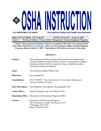
Air emissions from asphalt blowing are primarily hydrocarbon vapors vented with the blowingair. The quantities of emissions are small because of the prior removal of volatile hydrocarbons in thedistillation units, but the emissions may contain hazardous polynuclear organics. Emissions are30 kg/megagram (Mg) (60 lb/ton) of asphalt.13 Emissions from asphalt blowing can be controlled tonegligible levels by vapor scrubbing, incineration, or both.4,135.1.3 Fugitive Emissions And ControlsFugitive emission sources include leaks of hydrocarbon vapors from process equipment andevaporation of hydrocarbons from open areas, rather than through a stack or vent. Fugitive emissionsources include valves of all types, flanges, pump and compressor seals, process drains, coolingtowers, and oil/water separators. Fugitive emissions are attributable to the evaporation of leaked orspilled petroleum liquids and gases. Normally, control of fugitive emissions involves minimizing leaksand spills through equipment changes, procedure changes, and improved monitoring, housekeeping,and maintenance practices. Controlled and uncontrolled fugitive emission factors for the followingsources are listed in Table 5.1-2:-Oil/water separators (waste water treatment)StorageTransfer operationsCooling towersEmission factors for fugitive leaks from the following types of process equipment can be found inProtocol For Equipment Leak Emission Estimates, EPA-453/R-93-026, June 1993, or subsequentupdates:-Valves (pipeline, open ended, vessel relief)FlangesSeals (pump, compressor)Process drains5.1.3.1 Valves, Flanges, Seals, And Drains For these sources, a very high correlation has been found between mass emission rates and thetype of stream service in which the sources are employed. The four stream service types are(1) hydrocarbon gas/vapor streams (including gas streams with up to 50 percent hydrogen by volume),(2) light liquid and gas/liquid streams, (3) kerosene and heavier liquid streams (includes all crude oils),and (4) gas streams containing more than 50 percent hydrogen by volume. It is found that sources ingas/vapor stream service have higher emission rates than those in heavier stream service. This trend isespecially pronounced for valves and pump seals. The size of valves, flanges, pump seals, compressorseals, relief valves, and process drains does not affect their leak rates.17 The emission factors areindependent of process unit or refinery throughput.Valves, because of their number and relatively high emission factor, are the major emissionsource. This conclusion is based on an analysis of a hypothetical refinery coupled with the emissionrates. The total quantity of fugitive VOC emissions in a typical oil refinery with a capacity of52,500 m3 (330,000 bbl) per day is estimated as 20,500 kg (45,000 lb) per day (see Table 5.1-3). Thisestimate is based on a typical late 1970s refinery without a leak inspection and maintenance (I/M)program. See the Protocol document for details on how to estimate emissions for a specific refinery.5.1-12EMISSION FACTORS1/95
Table 5.1-2 (Metric And English Units). FUGITIVE EMISSION FACTORSFOR PETROLEUM REFINERIESaEMISSION FACTOR RATING: DEmission torscEmission skg/106 L coolingwater0.70.08Minimization of hydrocarbon leaksinto cooling water system;monitoring of cooling water forhydrocarbonslb/106 gal coolingwater60.7Minimization of hydrocarbon leaksinto cooling water system;monitoring of cooling water forhydrocarbonskg/103 Lwaste water0.60.024Covered separators and/or vaporrecovery systemslb/103 galwaste water50.2Covered separators and/or vaporrecovery systemsApplicable Control TechnologyStorageSee Chapter 7 - Liquid Storage TanksLoadingSee Section 5.2 - Transportation And Marketing Of Petroleum LiquidsabReferences 2,4,12-13.If cooling water rate is unknown (in liters or gallons) assume it is 40 times th
A refinery's processing flow scheme is largely determined by the composition of the crude oil feedstock and the chosen slate of petroleum products. The example refinery flow scheme presented in Figure 5.1-1 shows the general processing arrangement used by refineries in the United States for major refinery processes. The