Transcription
Continue4236751951 1775426364 10605029332 91168558786 3750114804 14330303.229508 542299590 53301305604 37446454292 8459034.0869565 96498343980 35750125488 20001683.072464 24457414212 26807197400 61069992.736842 131606803482 114888293280 48729012.952381 27343335704
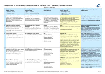
Aiag vda fmea manual pdf pdf downloader offlineAiag-vda fmea handbook pdf. Aiag & vda fmea handbook. Aiag vda fmea.It is implied that the need or expectation under consideration will apply to interested parties. 30 2.1 DESIGN FMEA 1ST STEP: SCOPE DEFINITION .30 2.1.1 Purpose .30 2.2 DESIGN FMEA2ND STEP: STRUCTURE ANALYSIS .33 2.2.1 Purpose .33 2.2.2 System .33 2.2.3 System FMEA.33 2.2.4 Component FMEA .33 2.2.5 Define the Customer .34 2.2.6 Block/Boundary Diagrams.34 2.2.7 Structure Trees .35 2.3 DESIGN FMEA 3RD STEP: FUNCTION ANALYSIS .37 2.3.1 Purpose.37 2.3.2 Function .37 -6- 2.3.3 Interface .38 2.3.4 Requirements.38 2.3.5 Product Characteristic .39 2.3.6 Parameter Diagram (P-Diagram) .39 2.3.7 Visualization of functionalrelationships .41 2.4 DESIGN FMEA 4TH STEP: FAILURE ANALYSIS .44 2.4.1 Purpose .44 2.4.2 Failures.44 2.4.3 The Failure Chain.45 2.4.4 Failure Network and Chain Analysis .46 2.4.5 Failure Effects.48 2.4.6 Failure Mode .49 2.4.7 Failure Cause .50 2.4.8 Summary.50 2.5 DESIGN FMEA 5TH STEP: RISK ANALYSIS.53 2.5.1 Purpose .53 2.5.2 Design Controls.53 2.5.3 Current Prevention Controls (PC) .53 2.5.4 Current Detection Controls (DC) .54 2.5.5 Confirmation of CurrentPrevention and Detection Controls .55 2.5.6 Evaluations .56 2.5.7 Severity (S) .56 2.5.8 Occurrence (O).57 2.5.9 Detection (D) .58 2.5.10 Action Priority (AP) .62 2.6 DESIGN FMEA 6TH STEP:OPTIMIZATION .66 2.6.1 Purpose .66 2.6.2 Assignment of Responsibilities .67 2.6.3 Status of the Actions.67 2.6.4 Assessment of Action Effectiveness .67 2.6.5 Continual Improvement .68 2.7 FMEA RESULTS DOCUMENTATION.70 3 EXECUTION OF THE PROCESS FMEA (PFMEA) . (e.g. ISO 26262 Functional Safety, SAE J3061 Cyber security) Customer Requirements Explicit (e.g. in customer specification) and implicit (e.g. freedomfrom prohibited materials) – under all specified conditions Internal requirements Product Specific (e.g. Requirements Specifications, manufacturability, suitability for testing, compatibility with other existing products, reusability, cleanliness, generation, entry and spreading of particles) Once customer requirements have been fully ascertained, thefunctions of the Items/System Elements in scope are derived from them. 2008: SAE J1739 4th Edition is the technical basis for the AIAG Reference Manual, with members of the J1739 work group contributing to the technical changes and improvements in the AIAG FMEA Reference Manuals. This person also accepts ownership of the content andfindings of the DFMEA. Process proven to demonstrated preventative conform to procedures and Best control. Control factors assigned to the functions are also presented. Typical failure causes may include the classic Ishikawa’s 4M, but are not limited to): Man: set-up worker, machine operator/ associate, material associate, maintenancetechnician etc. Can too much / too little / no material be used? Published by: Automotive Industry Action Group 26200 Lahser Road, Suite 200 Southfield, Michigan 48033 Phone: (248) 358-3570 Fax: (248) 358-3253 APPROVAL STATUS The AIAG Materials Management Steering Committee and designated stakeholders approved this document forpublication on Pending Release Date. There are different approaches and formats to the construction of a block diagram The block diagram indicates the interaction of components and subsystems within the scope of the design as well as those interfaces to the product Customer, Manufacturing, Service, Shipping, etc. Specific references to designfeatures that act to prevent a failure or line items in published test procedures will establish a credible link between the failure and the design control. “Function of Process Work Element” in the Function Analysis. This software ranges from dedicated FMEA software to standard spreadsheets customized to develop the FMEA. Major Changes A. It isused to evaluate the risks, valid at that time, in order to initiate actions to minimize them. Initial list of questions can be formed by reviewing the Cause column of current PFMEA's. Perceived quality of appearance, sound or haptics unacceptable to most customers Perceived quality of appearance, sound or haptics unacceptable to many customersPerceived quality of appearance, sound or haptics unacceptable to some customers - 99 - 1 No discernible effect Defective product triggers no reaction plan. 25 1.6.1.3.2 Lead Design/Process Engineer (Technical Lead) . The occurrence and detection evaluations should be reviewed when usingFMEA entries from previous products, due to the possibility of different conditions for the new product. The Severity evaluations of the failure effects should be transferred by the customer to the supplier, as needed. The focus of the analysis cascades from OEM to Tier 1 supplier to Tier N supplier. There are two views of FMEA examples shown in thismanual. It is important to consider is that the failure to conform to a product characteristic alone leads to the failure effect. 1.6.1 FMEA Team The FMEA team consists of multi-disciplinary (cross-functional) members who encompass the necessary subject matter knowledge. A statement “not fulfilled”, “not OK”, “defective”, “broken” and so on is notsufficient. Reduces product redevelopment timing and cost. In the case of using Structure Trees to develop elements, functions, and failures; a report view is also presented to show how the information may look when placed in a report. It is best to avoid lengthy discussions about low-risk issues. However, if the team determines that the new programis considered a minor change to the existing product, they may decide to leave the FMEA in the existing format. The FMEA project team should agree on an evaluation criteria and rating system, which is consistent even if modified for individual design analysis. Ship-to plant: the effect of the failure mode assuming the defect is not detected beforeshipping to the next plant (what action will the next plant take e.g. sort) 3. ii) Created Annex A1.1 Special Characteristics. This is the item that is topic of consideration of the failure chain. Similar application, with changes in duty cycle or operating conditions. To link failure cause(s) to a failure mode, the question should be “Why is the failure modeoccurring?” To link failure effects to a failure mode, the question should be “What hap-pens in the event of a failure mode?” Figure 3.4-2 - 84 - Example of Failure Analysis using a Structure Tree Figure 3.4-3 Relation between Failure analysis steps Following once again the header numbering (1, 2, 3) and color coding, by using the information in theFunction Analysis, begin building the Failure Chain. Figure 1.6-1 FMEA Timing (APQP Phases) - 27 - Figure 1.6-2 FMEA Timing (MLA Phases) 1.6.3 FMEA Intent Every member of the FMEA team needs to have the benefit of training about the purpose and intent of FMEA in order to make the time commitment needed perform a meaningful proactiveanalysis. Provides limited use in preventing a failure cause. 25 1.6.1.3.4 Core Team Members . 2.6.5 Continual Improvement The DFMEA serves as an historical record for the design. The reassessment should be based on the effectiveness of the Preventive and DetectionActions taken and the new values are based on the definitions in the Design FMEA Occurrence and Detection rating tables. A function structure becomes more detailed from top down. The violation of this duty - 17 - to ensure road safety can result in civil liability (in cases of product liability) on the part of the manufacturer and, in the event ofpersonal fault, claims of criminal liability (in cases of physical injury/death resulting from negligence) against the responsible associates. Functions describe the relationship between the input and output of an item/ system element with the aim of fulfilling a task. Failure Effects should be described in terms of what the customer might notice orexperience. ii) For PFMEA, ITEM is expanded to PROCESS ITEM, PROCESS STEP, and PROCESS WORK ELEMENT. 4 ACKNOWLEDGEMENTS . FMEA teams should focus on areas of risk that lead to root causes and effective corrective actions. The completedanalysis becomes a repository to capture the progression of design decisions and design refinements. The existence of an AIAG publication does not in any respect preclude anyone from manufacturing, marketing, purchasing, or using products, processes, or procedures not conforming to the publication. The structures arranged under each SystemElement are independent substructures (see figure 2.2-2). 1.6.4 FMEA Tools There are numerous FMEA software packages that can be used to develop a DFMEA and PFMEA as well as follow up on actions. Consider the criteria in the Process Experience column and Prevention Controls column, when determining the best Occurrence estimate. Thesuccess of the FMEA depends on active participation of the cross-functional team as necessary to focus on the topics of discussion. The clearly structured illustration of the complete system is thereby guaranteed by the fact that each system element exists only once to prevent redundancy. Similar process with some evidence of nonconformance.Provides some ability to prevent a failure cause. Process has been tried and Capable of finding deficiencies in the tested with successful results process related to the failure. The design documents comprehend legal requirements (e.g. lead-free material), industry requirements (e.g. thread class), customer requirements (e.g. quantity), and internalrequirements (e.g. part cleanliness). Current Detection controls must be clearly and comprehensively described. Actions are not intended to be used for activities that are already planned as these are documented in the Prevention or Detection Controls, and are already considered in the initial risk analysis. The organization determines the bestapproach or format for the Block/Boundary diagram. Table P2 No discernible effect. Is the item a carryover product or similar to a previous level item? F&P America Manufacturing Knorr-Bremse Systeme fur Nutzfahrzeuge GmbH Gunite Nexteer Automotive Huhn ON Semiconductor IMS Gear Robert Bosch GmbH Iroquois Industries SchaefflerTechnologies AG & Co KG Litens VW Group Magna International Inc. The FMEA project team should agree on an evaluation criteria and rating system, which is consistent, even if modified for individual product analysis. - 29 - 2 EXECUTION OF THE DESIGN FMEA The Design FMEA is carried out in six steps. A new method: Supplemental FMEA forMonitoring and System Response (FMEA-MSR) is added, which provides a means for the analysis of diagnostic detection and fault mitigation during customer operation for the purpose of maintaining a safe state or state of regulatory compliance. Identical mature design. All potential failures identified in the FMEA must be dealt with, i.e. it isnecessary to document either that the level of risk is acceptable, that actions to reduce the risk are not being implemented (for business reasons), or (in a traceable manner) which actions have been performed when and by whom. Work Group Members Validation Testing Participants Audi AG Accuride Corporation Continental Teves AG Axalta CoatingSystems Daimler AG Benteler Daimler Truck North America Craemer FCA US LLC Delphi Ford Motor Company Dr. Schneider General Motors EBK Honda of America Mfg., Inc. - 41 - Figure 2.3-4 Example of Function Analysis using a Structure Tree The function structure can be created in the Functional Analysis section of the Spreadsheet:FUNCTION ANALYSIS (STEP 3) 1. Has an engineering analysis (e.g. reliability) been used to estimate the expected comparable occurrence rate for the application? Procedures and best practices exist but are insufficient to ensure that the failure will not occur. Figure 3-1 3.1 FMEA Steps Process FMEA 1st Step: Scope Definition 3.1.1 Purpose Thepurpose of the Process Scope Definition is to describe what product/processes are to be included or excluded for review in the PFMEA project. This may be a reference to a specification sheet in a catalog. 24 1.6.1.2 The Process FMEA Team . Practices, consideringLessons Learned. An obligatory requirement is often associated with safety documentation or regulatory directives that the customer must comply with. Failure Mode (FM) of the Process Step Axial position of sintered bearing is not reached, gap too small Axial position of sintered bearing is not reached, gap too small axial position of sintered bearingis not reached, gap too large View of Process Step-Function-Failure in Spreadsheet 3. The inputs to the product and outputs from the product, i.e. the intended functions and side effects of the product, environmental influences, noise factors, and control factors are useful in identifying unintended outputs. reworked in station Additional defectiveproducts before it is processed. “Elastic” or emotionally laden terms (dangerous, intolerable, irresponsible, etc.) must absolutely be avoided. Here, technically precise wording must be used, enabling a specialist to assess failures and possible consequences. Legal and Corporate policy must be observed with respect to passing FMEAs on to customers.If so, then identify the potential impact on the “process item” and “end user” in the PFMEA. The process takes into account that all processes within the facility can be analyzed or reanalyzed using PFMEA. After the tests are finalized the preliminary rating has to be confirmed or adapted, when indicated. 3.4.5 Failure Effects Failure Effects arerelated to functions of the process item (System, Subsystem, Part Element or Name of Process). 2 Very low occurrence during manufacturing or assembly. All, some, or no types of effects may apply depending on the failure mode and its consequences. 100% of production run Line shutdown up to one hour. Sources for this should also include acomparison of - 88 - similar processes and a review of customer (End User and subsequent operation) claims relating to similar components. This information is important in defining the “positive” functions and requirements needed for the Functional Analysis. Separate tables are used to assess Action Priority in DFMEA, PFMEA, and FMEA-MSR. Thedescription of a function must be clear. Assume that the failure mode could occur but may not necessarily occur. Example: Press in sintered bearing to pole housing - 79 - The Process Work Element function reflects the contribution to the Process Step to create the process / product features. The detection rating is initially a prediction of theeffectiveness of any yet unproven control. Milieu/Environment: ambient conditions such as heat, dust, contamination, lighting, noise, etc. Function or Outcome of the Process Step and Characteristic Description (Quantitative value is optional) Press in sintered bearing to achieve axial position in pole housing to max gap per print Press in sinteredbearing to achieve axial position in pole housing to max gap per print Press in sintered bearing to achieve axial position in pole housing to max gap per print 2. The FMEA method is an integral element of Product Development and Process Development activities. The main objectives of a Process Function Analysis are: Overview of thefunctionality of process Visualization of the process functions using a process flow diagram or function net (based on the Structure Analysis) Association of characteristics to functions and functions to process elements (see six step) Cascade of customer (external and internal) functions with associated requirements Basis for Failure Analysis 3.3.2Function A function describes what the process item or process step is intended to do. - 33 - 2.2.5 Define the Customer There are two major customers to be considered in the FMEA analysis; all may be taken into account: END USER The individual who uses a product after it has been fully developed and marketed. An AIAG publication is intendedas a guide to aid the manufacturer, the consumer, and the general public. (e.g. product or process design, fixture and tool design, established process sequence, - 97 - production control tracking/traceability, machine capability, and SPC charting) 3.5.10 Detection (D) Detection is the rating associated with a prediction of the most effective processcontrol from the listed detection-type process controls. Predicts conformance of production design. The focus element of the failure structure is the failure mode, with its associated failure effects and failure causes. - 74 - 3.2 Process FMEA 2nd Step: Structure Analysis 3.2.1 Purpose The purpose of Process Structure Analysis is to identify andbreakdown the manufacturing system into Process items, Process steps, and Process Work Elements. - 15 - 1996: VDA volume 4, part 2, Quality Assurance Prior to Serial Application was published with the subtitle System FMEA. NOTE: In some cases, the team conducting the analysis may not know the end user effect (e.g. catalogue parts, off-theshelf products, Tier 3 components). 3.4.7.4 Environment 1. Completed Completed actions have been implemented and their effectiveness has been demonstrated and documented. Loss of convenience function. The team should assume that the basic design of the product is correct; however, if there are design issues which result in process concerns,those issues should be communicated to the design team for resolution. Noncompliance with regulations. Process Step is a manufacturing operation or station. After implementation of any unproven control, the effectiveness can be verified and re-evaluated. NOTE: Reference the NOTE in section 2.4.5 for cases when the end use is not known. Newuse case, or change in duty cycle / operating conditions. 2.6.4 Assessment of Action Effectiveness When an action has been completed, Occurrence, and Detection values are reassessed, and a new Action Priority may be determined. 2.3.2 Function A function describes what the item/ system element is intended to do. As a consequence, redundanciesare unavoidable. FMEA InTent – Why are we here? Process has been tried and tested with successful results in series production. 2.5.4 Current Detection Controls (DC) Current Detection Controls detect the existence of a failure cause or the failure mode before the item is released for production. There may be more than one function for eachprocess item or process step. A failure mode can have multiple effects relating to internal and external customers. Can parts be damaged - From pickup to application? The evaluations of the failure effects should be mutually agreed to by the customer and the organization. However, original S, O, D ratings may be modified for basis, family or genericDFMEAs because the information is used as a starting point for an application-specific analysis. The DFMEA team should also consider margin of safety in design as a prevention control. Focus Element Electrical Motor Figure 2.4-9 View of Product Step-Function-Failure in Spreadsheet 3. The focus element of the failure structure is the Failure Mode,with its associated Failure Effects and their Failure Causes. (5T’s) Define the boundaries of the analysis – what is included, what is excluded? 1.4.5 Reuse of the FMEA Existing FMEAs for known products and processes (often called generics, baselines, product family FMEAs, etc.) are used as a basis for new analyses in order to ensure that knowledgeis accumulated over product lifecycles and that prior performance issues are not repeated. Ability of detection control to detect the failure cause or failure mode is very low based on verification or validation procedure, sample size, mission profile, etc. Since interfaces can contain up to fifty percent or more of the total failure modes, it is essential thatany FMEA carefully consider the interfaces be-tween subsystems and components in addition to the content of the sub-systems and components themselves. Can automated process be interrupted? A - 39 - P-Diagram may be used as necessary to show the influences on a system element. Use Case or operating conditions vary widely and cannot bereliably predicted. The AP Table provides the logic details for the FMEA team for all 1000 possible combinations of S, O. Is lighting adequate for task? - 67 - However, the status of the action remains “implementation pending” until the effectiveness has been tested. Note for spreadsheet users: It is recommended that users start with the failure modeand then identify related failure effects using the information in the #1 Function of the Process Item column of the Function Analysis section because some or all categories may apply. From parts available within the process, can wrong part be applied? A portion of the Line shutdown 1 hour Full production run may have Production Shift. - 34 Figure 2.2-1 Block/Boundary Diagram 2.2.7 Structure Trees The structure tree arranges system elements hierarchically and illustrates the dependency via the structural connections. The header includes some of the basic PFMEA scope information, as follows: Company Name: Name of company of the PFMEA Plant Location: What is the location ofthe plant - Geographical designation for manufacturing and/or line unique identifier Customer Name: Name of customer(s) for this document and System / Subsystem / Component / Part Model Year / Platform Starting vehicle model year and/or vehicle program as applicable Subject: Name of PFMEA project PFMEA Start Date: The date on which thePFMEA project started Cross-Functional Team: Team whose members include personnel from the organization and may include customer and supplier representatives; team members may be internal or external to the organization PFMEA Revision Date: The revision of the specific unique PFMEA document (latest date it was changed) PFMEA IDNumber: A unique identification number for the PFMEA document - 73 - Process Responsibility: Name of person who is responsible for the PFMEA Confidentiality Level: The level of confidentiality determined by the PFMEA owner, e.g. Internal Business Use, Proprietary, Confidential. (e.g. work instructions, set-up and calibration procedures,preventive maintenance, error-proofing verification procedures, and process monitoring verification checklists) Are technical error-proofing solutions implemented? Moderate occurrence during intended service life of the item. Continuous Improvement History column added / Authorization column changed. The table may be augmented to includeproductspecific examples. 112 4.1 FMEA-MSR 1ST STEP: SCOPE DEFINITION .113 4.2 FMEA-MSR 2ND STEP: STRUCTURE ANALYSIS .114 4.2.1 Block (Boundary)Diagrams.114 4.2.2 Structure Trees .114 4.3 FMEA-MSR 3RD STEP: FUNCTION ANALYSIS .116 4.4 FMEA-MSR 4TH STEP:FAILURE ANALYSIS .
Aiag vda fmea manual pdf pdf downloader offline Aiag-vda fmea handbook pdf. Aiag & vda fmea handbook. Aiag vda fmea. It is implied that the need or expectation under consideration will apply to interested parties. 30 2.1 DESIGN FMEA 1ST STEP: SCOPE DEFINITION .30 2.1.1 Purpose .30 2.2 DESIGN FMEA
