Transcription
187 E. 670 S., Kamas, UT 84036435.783.6040 888.796.2476https://wkfluidhandling.comPSD06 Owner’s ManualManuals available online at: wkfluidhandling.com/owners-manualsManual Part #18200-LM-0041 Copyright 2022 White Knight Fluid Handling A Graco company3/23/2022 Version 1.1.5
Page left intentionally blank Copyright 2022 White Knight Fluid Handling A Graco company3/23/2022 Version 1.1.5
187 E. 670 S., Kamas, UT 84036435.783.6040 888.796.2476Table of Contents1 Introduction . 12 Specifications & Performance . 22.1 Pump Specifications . 22.2 PSD06 Performance Curves . 32.3 PSD06 Dimensional Drawing . 42.4 PSD06 Exploded View Drawing . 53 Installation . 73.1 Installation Precautions . 73.2 PSD Installation Advantages . 83.3 System and Pump Environment . 83.4 Control and Monitoring Connections . 93.5 PSD 06 Installation Instructions . 104 Pump Service & Rebuilds. 114.1 PSD Ordering instructions . 114.2 PSD06 Rebuild Kit Ordering Instructions . 124.3 Alternative Wet Kit Ordering Instructions . 144.4 Tools . 154.5 Torque Instructions . 154.6 Disassembly Instructions. 164.7 Assembly Instructions . 185 Accessories . 206 Warranty . 217 Certificate & Declaration of Conformity . 22Manual content and data are subject to change without notification.Manuals available online at: wkfluidhandling.com/owners-manuals Copyright 2022 White Knight Fluid Handling A Graco company3/23/2022 Version 1.1.5
187 E. 670 S., Kamas, UT 84036435.783.6040 888.796.24761 IntroductionThank You for Purchasing White Knight ProductsYou have purchased a White Knight product that has been designed to our exactingspecifications and built by a team of technicians with the highest commitment to quality!White Knight is the world leader in zero-metal, ultra-high purity pumps and continues to drivethe industry with new technology and products. Since the inception of White Knight in 1995,we have been awarded over 14 US design patents and have multiple other patentspending! White Knight currently produces over 30 sizes/models of pumps in varying materialsto meet our customers’ stringent requirements in numerous applications, including ultra-hightemperature re-circulation; high pressure chemical delivery systems, slurry, industrial chemical,and industrial applications.White Knight has received many prestigious awards for its designs and continues to lead theindustry in quality because White Knight controls the manufacturing process from rawmaterials to finished goods in our facility located in Kamas, UT. This allows us to rigorouslymanage our quality control process to ensure that our strict cleanliness procedures are alwaysfollowed and that components are built under consistent methods and conditions for maximumreliability.Our strict manufacturing process controls include assembling and testing White Knightproducts in a clean environment. White Knight products also pass a battery of functional teststo ensure operational integrity.Before installing your White Knight product, please carefully review the product manual. Thereare many helpful hints and ways to optimize the setup and use of your White Knight product aswell as instructions and requirements for installation. In addition, you will also find manyaccessories in the manual that will enhance the functionality of your White Knight product.Our team has gone to great lengths to provide you with the highest quality products at the bestvalue and we back them up with excellent warranties and world class support! We hope youagree our products will serve your exacting needs and meet your stringent requirements everytime you purchase a White Knight Product.Sincerely,Steve SmithPresidentWhite Knight Fluid Handling Page 1Copyright 2022 White Knight Fluid Handling A Graco company3/23/2022 Version 1.1.5
187 E. 670 S., Kamas, UT 84036435.783.6040 888.796.24762 Specifications & Performance2.1 Pump SpecificationsPSD06 Pump Performance Specification1FlowRateTheoreticalDisplacementPer CycleSuctionLift WetSuctionLift DrySoundPressure3dB(a)SoundPower3dB(a)28 lpm(7.4 gpm)0.04 L(0.011 gal)9.5 m(31.2 ft2)3m(10 ft)60.282.0454.4566.1Max.Size ofPassibleSolids42 mm(0.08 in)MaxOperatingTemperature100 C TE70 C UHAirSupplyPressureLimits530 psi(100 psi)All tests performed with water at ambient temperatures and PTFE check balls.1. Pump Specifications are subject to change based on configuration ordered2. Suction lift diminishes with wear of pump, minimize suction lift to maximize performance3. dB Level at 100 psi 50 CPM (top) and 100 psi maximum CPM (bottom)4. The passing of solids may shorten the life of the pump5. Minimum startup pressure (Max supply pressure)STORAGEPSD pumps that are not put into operation upon delivery must be stored in an environment where they areprotected from moisture, extreme temperatures, UV radiation, vibration, and should be kept clean. White Knightrecommends an environment of ambient temperature (between 60 F (15 C) and 80 F (25 C)) with a humiditylevel below 65%.Maintenance and Torque ValuesUpon installation of the pump, as well as after a few hours of operating the pump, the head and manifold boltsmust be re-torqued. Tie bolts and manifold bolts must be re-torqued to values specified in the table below.Re-torqueing will be required after the pump has set for extended periods of time, run in thermal cyclingapplications, been dismantled, or when there is a large difference between environmental temperatures and fluidtemperatures. See torqueing instructions on page 15.Tie BoltsManifold BoltsAssembly Torque in-lbs. (kg-cm)20 (23.0)20 (23.0)Re-torque Spec in-lbs. (kg-cm)15 (17.3)15 (17.3) Copyright 2022 White Knight Fluid Handling A Graco company3/23/2022 Version 1.1.5Page 2
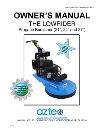
187 E. 670 S., Kamas, UT 84036435.783.6040 888.796.24762.2 PSD06 Performance Curves Page 3Copyright 2022 White Knight Fluid Handling A Graco company3/23/2022 Version 1.1.5
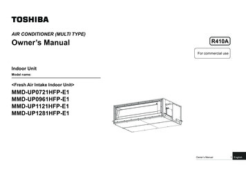
187 E. 670 S., Kamas, UT 84036435.783.6040 888.796.24762.3 PSD06 Dimensional Drawing Copyright 2022 White Knight Fluid Handling A Graco company3/23/2022 Version 1.1.5Page 4
2.4 PSD06 Exploded View Drawing187 E. 670 S., Kamas, UT 84036435.783.6040 888.796.2476 Page 5Copyright 2022 White Knight Fluid Handling A Graco company3/23/2022 Version 1.1.5
187 E. 670 S., Kamas, UT 84036435.783.6040 888.796.2476 Copyright 2022 White Knight Fluid Handling A Graco company3/23/2022 Version 1.1.5Page 6
187 E. 670 S., Kamas, UT 84036435.783.6040 888.796.24763 Installation3.1 Installation PrecautionsRequired Air Flow and Operating PressureRequired Air Flow for the PSD06 is ⅛” minimum orifice unrestricted. An adaptor is included for ⅛”NPTor ⅛” BSPT with all pumps, NPT or BSPT is decided on based on the liquid fittings requested. Max airsupply for the PSD06 is 7 Bar (100 PSI).Restriction of Liquid Inlet LineRestricting the liquid supply of the pump forces the pump to work harder than normal and should beavoided whenever possible, especially when pumping viscous liquids. Attempting to operate the pumpagainst a closed liquid inlet will cause serious damage to the pump, and will void the warranty. If youwish to slow or stop your pump this may be done by closing off the liquid outlet.Supply Pressure RecommendationsThe life of your pump may be extended significantly by operating your pump 30%-40% below redlineoperating supply pressures. The use of undersized regulators, valves, and supply lines can decreasepump performance and longevity significantly.OrientationWhite Knight does not recommend installing your pump in any position other than its upright position.Check valves within White Knight PSD pumps are actuated by gravity and/or flow and perform optimallyin the upright position.Failure PotentialIt is possible that the diaphragm may fail. In such a situation, it is possible that chemical could enter theair side of the pump, and may even escape through the muffler. In such a situation, the muffler mediamust be replaced and the air side purged. White Knight recommends the implementation of a one-wayvalve on the air side to protect air lines from contamination in the event of a diaphragm failure.MufflerPump performance may be restricted in the event of a clogged muffler. Regular inspection of air linesand muffler media is recommended to maintain performance.Product TestingEach pump is tested before being packaged for shipment. White Knight recommends the flushing ofeach pump before servicing if water can contaminate the process. Page 7Copyright 2022 White Knight Fluid Handling A Graco company3/23/2022 Version 1.1.5
187 E. 670 S., Kamas, UT 84036435.783.6040 888.796.24763.2 PSD Installation AdvantagesHead Pressure / Dead-HeadWhite Knight PSD pumps may be controlled by opening and closing the outlet of the pump and may beinstalled in any head pressure situation up to dead-head. Dead-head occurs when air supply pressureand the liquid line (head) pressure are equal. Dead-head conditions allow for no flow. Under dead-headconditions the PSD will cease to cycle (limiting wear) until conditions change allowing for flow.Passing SolidsAll damage caused by passing solids (wafer shards, etc.) is coverable under warranty when your pumpis used in conjunction with a White Knight Catcher pre-pump filter.Running DryWhite Knight PSD pumps are capable of running dry without damage other than normal wear to thepump. When a pump is run dry, it cycles faster than normal, accelerating the rate of “normal wear”.3.3 System and Pump EnvironmentClean Dry Supply Air (CDA)Operation of the point of 5 PSD06 requires class 4 quality air for particles, moisture, and oils.(maximum particle size 15 microns, 3 C Dew 5 mg/mᵌ) per ISO8573 – 1.Flammable SolventsAny system used to pump flammable solvents should be properly grounded. A test from River’s Edgeon using isolative pumps to pump flammable liquids indicated that the liquid itself must be groundedand that other procedures should be followed. A copy of the test is available upon request fromWhite Knight.Abrasive SlurriesFor slurry applications, White Knight recommends use of the PSD UH pump.Pumping Liquids Near Boiling PointThe boiling point of a liquid is reduced under vacuum (suction) conditions. Due to the vacuum causedby a pump, liquid could boil in the inlet line of the pump when it is not boiling in the tank (or anothersupply reservoir). Placing the pump as close as possible to the tank and with as little vertical lift aspossible (the pump being flooded by gravity is ideal) minimizes boiling in the inlet line. Boiling of theliquid in the inlet line causes a pump to “race” and accelerates the wear of the pump. Boiling liquids maycause cavitation to occur. Damage to wearable or non-wearable components of the pump caused bycavitation is not covered under warranty.Running a Submerged PumpWhen running the PSD in submerged mode, the exhaust air must be sealed and redirected above thesurface of the media. Take care that all pump parts (air side and wet side) are resistant to the mediabeing used. It may be necessary to mount the pump to the bottom of the tank. Operating this pumpwhile submerged requires use of a remote muffler adaptor kit.TemperatureThe PSD may be operated safely in low temperature applications. Take care to avoid freezing orcrystallization of the fluid inside or outside of the pump. Running the pump at temperatures belowfreezing may accelerate the wear of the elastomer components within the pump. In applications wherethe media or pump temperature varies, torque values (tension) of the manifold and head bolts must bemonitored. TE versions of the PSD Series pumps can be operated at temperatures up to 100 C(212 F). UH versions of the PSD Series pumps can be operated at temperatures up to 70 C (158 F). Copyright 2022 White Knight Fluid Handling A Graco company3/23/2022 Version 1.1.5Page 8
187 E. 670 S., Kamas, UT 84036435.783.6040 888.796.24763.4 Control and Monitoring Connections PUMP MONITORING: Pump monitoring can be performed by solid state pressure switch monitoring. Thisoption is described on our website in the accessories section and is available for new orders and forretrofits in the field.Conductivity Leak Detection1.2.Pressure Switch Stroke Detection1.2.3.Pump Control:Run mode and flow rate are two of the itemswhich the CPT-1 can control/monitor. Page 9Copyright 2022 White Knight Fluid Handling A Graco company3/23/2022 Version 1.1.5
187 E. 670 S., Kamas, UT 84036435.783.6040 888.796.24763.5 PSD 06 Installation Instructions2.1. Fix base plate to work station with four 3/8” or 10 mm bolts.(Bolts not included.)3.Attach ⅜” liquid fittings topump. Excessive forcemay damage threads. Use appropriateadapter for 1/8”BSPT or NPTEnsure airline is free of solids beforeattaching. Supply air via ⅛” NPT airfitting with flexible connection.Inlet/Outlet ConfigurationsOutletInletSome configurations require re-orientation of crossover manifolds. See Disassembly and AssemblyInstructions.Recommended Set UpPressure GaugeShut off valveShut off valveSupply AirDischarge LineFilter RegulatorFlexible ConnectionShut off valveVacuum GaugeShut off valveSuction LineShut off valveAir DryerCaution: Closing suction line while pump is operating will cause irreversible damage to the pump. Copyright 2022 White Knight Fluid Handling A Graco company3/23/2022 Version 1.1.5Page 10
187 E. 670 S., Kamas, UT 84036435.783.6040 888.796.24764 Pump Service & Rebuilds4.1 PSD Ordering instructions Page 11Copyright 2022 White Knight Fluid Handling A Graco company3/23/2022 Version 1.1.5
187 E. 670 S., Kamas, UT 84036435.783.6040 888.796.24764.2 PSD06 Rebuild Kit Ordering InstructionsStandard Rebuild KitsPart NamePart NumberPSD06 Dry Rebuild KitPSD06TE-OT Wet Rebuild KitPSD06TE-ET Wet Rebuild KitPSD06TE-NT Wet Rebuild KitPSD06UH-OT Wet Rebuild KitPSD06UH-ET Wet Rebuild KitPSD06UH-NT Wet Rebuild KitPSD06TE-OT Combined Rebuild KitPSD06TE-ET Combined Rebuild KitPSD06TE-NT Combined Rebuild KitPSD06UH-OT Combined Rebuild KitPSD06UH-ET Combined Rebuild KitPSD06UH-NT Combined Rebuild 6UH-ET-1*RBPSD06UH-NT-1**Combined kits contain all components for the wet kit as well as the dry kit.Kit ComponentsParts Included in RBPSD06-1:Part m Shaft for WK Pump, PSD06Threaded Stud for WK Pump, PSD06, SSBaffle, Porous PolyRing, 0.0625 Thick, PSD04/06#13 O-ring SealGlide Seal for PSD04 ShaftPTFE Lubricant, Squeeze TubePSD04/06 Main Sleeve AssemblyPSD04/06 Center Sleeve Assembly122242111Parts Included in RBPSD06TE-OT:Part -00104135-MP-00114137-TE-0008DescriptionCap Plug for WK Pump, PSD04/06PTFE Diaphragm for WK Pump, PSD061/2" Check Ball, PTFERetainer, Ball, 1/2", PTFE, TopPSD06TE Check SeatRetainer, Ball, 1/2", PTFE, BottomQuantity2024242Parts Included in RBPSD06TE-ET:Part 00014142-TE-00104135-MP-00114137-TE-0008Cap Plug for WK Pump, PSD04/06EPDM Diaphragm for WK Pump, PSD061/2" Check Ball, PTFERetainer, Ball, 1/2", PTFE, TopPSD06TE Check SeatRetainer, Ball, 1/2", PTFE, BottomQuantity2024242 Copyright 2022 White Knight Fluid Handling A Graco company3/23/2022 Version 1.1.5Page 12
187 E. 670 S., Kamas, UT 84036435.783.6040 888.796.2476Parts Included in RBPSD06TE-NT:Part -00104135-MP-00114137-TE-0008DescriptionCap Plug for WK Pump, PSD04/06Buna Diaphragm for WK Pump, PSD061/2" Check Ball, PTFERetainer, Ball, 1/2", PTFE, TopPSD06TE Check SeatRetainer, Ball, 1/2", PTFE, BottomQuantity2024242Parts Included in RBPSD06UH-OT:Part -00104135-MP-00114137-TE-0008DescriptionCap Plug for WK Pump, PSD04/06PTFE Diaphragm for WK Pump, PSD061/2" Check Ball, PTFERetainer, Ball, 1/2", PTFE, TopPSD06TE Check SeatRetainer, Ball, 1/2", PTFE, BottomQuantity2024242Parts Included in RBPSD06UH-ET:Part -00104135-MP-00114137-TE-0008DescriptionCap Plug for WK Pump, PSD04/06EPDM Diaphragm for WK Pump, PSD061/2" Check Ball, PTFERetainer, Ball, 1/2", PTFE, TopPSD06TE Check SeatRetainer, Ball, 1/2", PTFE, BottomQuantity2024242Parts Included in RBPSD06UH-NT:Part -00104135-MP-00114137-TE-0008DescriptionCap Plug for WK Pump, PSD04/06Buna Diaphragm for WK Pump, PSD061/2" Check Ball, PTFERetainer, Ball, 1/2", PTFE, TopPSD06TE Check SeatRetainer, Ball, 1/2", PTFE, BottomQuantity2024242 Page 13Copyright 2022 White Knight Fluid Handling A Graco company3/23/2022 Version 1.1.5
187 E. 670 S., Kamas, UT 84036435.783.6040 888.796.24764.3 Alternative Wet Kit Ordering InstructionsListed on page 12 are the standard rebuild kits offered by White Knight. Configurable wet kits are available forpurchase. To configure an alternative, rebuild kit use the graphical ordering instructions shown below. Copyright 2022 White Knight Fluid Handling A Graco company3/23/2022 Version 1.1.5Page 14
187 E. 670 S., Kamas, UT 84036435.783.6040 888.796.24764.4 ToolsPart NameMuffler Cap WrenchSleeve Cap ToolFour pin wrench used toremove/install the muffler cap(included with pump). Hex is for usewith a 19mm or ¾” socket drive.(12100-PV-0043)Part Number12100-PV-004312100-PV-0030QTY.11Tool for inserting and removingthe sleeve cap (included withpump)(12100-PV-0030)4.5 Torque InstructionsManifold BoltsTie BoltsTie bolts (purple) on both sides must be torquedbefore manifold bolts (blue) on top and bottom.Torqueing of tie bolts should be done in a crossingfashion, as shown at right.There is no particular order for torqueing manifoldbolts other than they must be done after head blots.Apply Loctite Antiseize Lubricant LB 8012 (orequivalent) to all bolts. This procedure must be followedfor assembly and also re-torqueing of bolts.Tie BoltsManifold BoltsAssemblyTorquein-lbs. (kg-cm)20 (23.0)15 (17.3)Re-torqueSpecin-lbs. (kg-cm)15 (17.3)10 (11.5)①①③⑥⑤④②① Page 15Copyright 2022 White Knight Fluid Handling A Graco company3/23/2022 Version 1.1.5
Copyright 2022 White Knight Fluid Handling A Graco company3/23/2022 Version 1.1.5Page 16 4.Use 3 mm Allen Wrench to removeoutlet manifold.Remove all plastic caps.1.4.6 Disassembly Instructions 3. 6.Reattach manifold bolts toheads, to keep the manifoldnuts aligned.Remove bottom O-ring, and check valve parts.Without scratching the inner bore, use a hook toremove the check cages.Remove top check valve parts following thesame process described in step 3.5.Use 3 mm Allen wrench to removepump base feet and inlet manifold2.187 E. 670 S., Kamas, UT 84036435.783.6040 888.796.2476
Page 17Copyright 2022 White Knight Fluid Handling A Graco company3/23/2022 Version 1.1.5Servicing of Pump11. 9.Use the appropriatePVC tool to removethe muffler from thepump body.Press out the Main SleeveAssembly; Remove anydebris from the pump body.Remove diaphragms by peeling one backand turning it counter-clockwise. Slidethe second diaphragm out with the shaft.Remove the Sleeve Caps using the PVCTool included with the pump. Remove theGlide Seal and O-ring on the ID of the Caps 8.Before servicing the pump verify that the pump has been drained and purged so as to minimize the potential ofphysical damage and maximize the safety of service personnel. 10.Use 7 mm socket to remove nuts from boltson one side of head. Remove both retainerrings and heads.7.187 E. 670 S., Kamas, UT 84036435.783.6040 888.796.2476
Assemble Top Check; first insert topcheck seat, then ball, then topcheck cage. Repeat for both headsReplace O-ring in seat for Air Sleeve Cap.Apply Loctite 425 or equivalent to threads oncap. Attach a cap to the pump using theappropriate PVC tool included with the pump.4. 1.4.7 Assembly Instructions 5.Lubricate O-rings on main sleeve assembly.Spread lubricant evenly across the O-rings.Clear any holes blocked with lubricant.Place O-ring into ID of Sleeve Caps. Follow byinserting the glide seal. Fold glide seal into akidney bean and insert into the id. Press flat onall diameters. Replace O-ring in face of Caps2. 3.6. Press Main Shaft Assemblyinto Body. Take care that theO-rings do not displacethemselves from the mainsleeve assembly.Replace muffler media andattach to pump body. Orderof muffler media is critical.187 E. 670 S., Kamas, UT 84036435.783.6040 888.796.2476 Copyright 2022 White Knight Fluid Handling A Graco company3/23/2022 Version 1.1.5Page 18
10. 7. Remove the manifold bolts from theheads, and insert bottom checkcages, balls, and seats. In that order.Replace O-ring in groove for the second cap, and attach the second capper instructions in step 4. Tighten untilcap bottoms out.8.12.Apply antiseize lubricant to each tie bolt.Thread tie bolts onto head retaining rings, alignhead side 1, body, head side 2, and retainingring 2 onto tie bolts and clamp together.Washer order is critical. DO NOT TIGHTEN. Return to page 15 and followtorque instructions. Replace allbolt covers.The manifolds may be rotated 180 tocustomize the direction of the liquid inletand outlet. 9.Align the bottom manifold, and bottom manifoldretainers, and attach with manifold bolts (applyantiseize lubricant to each bolt). Note order anddirection of washers. Repeat for top manifold. DONOT TIGHTEN11.Remove Thread cover on diaphragm, andattach to the pump shaft. Verify that theshaft is firmly attached – no gap. Pass intopump body, and attach other diaphragm.Apply Loctite 242 (or equivalent) to bothends of each threaded stud187 E. 670 S., Kamas, UT 84036435.783.6040 888.796.2476 Page 19Copyright 2022 White Knight Fluid Handling A Graco company3/23/2022 Version 1.1.5
187 E. 670 S., Kamas, UT 84036435.783.6040 888.796.24765 AccessoriesRemote Muffler Adaptor Kit- (Not included with pump.) Required if pump is to be submerged.Pump Catcher Inline options available.Large through holes to avoid loading.Filter may be removed without removing the Catcher from the pump or the line.If a pump were damaged by passing solids while using the Catcher it would be repaired underwarranty.Control & Monitoring OptionsStroke Detection Solid State Pressure Switch SP1Leak Detection Conductivity Leak Detection LC0Control Options – Run mode and flow rate are a few of the items which the CPT-1 can control/monitor. Copyright 2022 White Knight Fluid Handling A Graco company3/23/2022 Version 1.1.5Page 20
187 E. 670 S., Kamas, U
Thank You for Purchasing White Knight Products . You have purchased a White Knight product that has been designed to our exacting specifications and built by a team of technicians with the highest commitment to quality! White Knight is the world leader in zero-metal, ultra-high purity pumps and continues to drive