Transcription
TECO SG2 Micro-ControllerOperation ManualVersion:First Edition -DC 24VI1 I2I3I4I5I6 A1 A2Input X1 X2 X3 X44 ACInput X1 X2 X3 X44 ACLInput 8 x DC(A1,A2 0 10V)NLAC 100 240VNAC 100 240VRunRunSG2-12HR-DSG2-8ER-ASG2-8ER-AOutput 4 x Relay / 8AOutput 4 x Relay / 8AOutput 4 x Relay / 8AQ1 Y1Q2-DC 24VQ3I1 I2I3I4I5I6 A1 A2Y4LNOutput 4 x Relay / 8A -I1 I2DC 24VI5AC 100 240VRunSG2-8ER-ASG2-8ER-AOutput 4 x Relay / 8AY3Q4I4NOutput 4 x Relay / 8AY1I3LRunSG2-12KR-DQ3Y4Input X1 X2 X3 X44 ACAC 100 240VRunQ2Y2Y3Input X1 X2 X3 X44 ACInput 8 x DC(A1,A2 0 10V)Q1Y1Y2Y3Q4I6I7I8A1 A2 A3 A4Y2Y1Y4Y3Input X1 X2 X3 X44 ACLInput 12 x DC(A1.A4 0 10V)NAC 100 240VY2Y4Input X1 X2 X3 X44 ACLNAC 100 240VRunRunSG2-20HR-DSG2-8ER-ASG2-8ER-AOutput 4 x Relay / 8AOutput 4 x Relay / 8AOutput 8 x Relay / 8AQ1Q2 -Y1Q3I1 I2I3Q4I4I5Q5I6I7I8DC 24VQ6I9Q7Q8IA IB ICY2Y3Y4Input X1 X2 X3 X44 ACLInput 8 x DCNAC 100 240V20KT-DOutput 8 x Tra. / 0.5AT2T3Y4Input X1 X2 X3 X44 ACLNAC 100 240VRunSG2-8ER-ASG2-8ER-AOutput 4 x Relay / 8AOutput 4 x Relay / 8AY1T4Y2RunRunT1Y1Y3T5T6T7T8Y3Y2Y4Y1Y3Y2Y4
20KR-1212*8Relay128Relay4 DStandard Variant without up-cover 20CR-A 20CR-D 12*8Relay4 20CT-D 12*8Transisto4 r 20CR-12D12*8Relay4 High-speed communication Variant20VR-D 12*8Relay4 20VT-D 12*8Transisto4 r Expansion8ER-A44Relay8ER-D 44Relay8ET-D 44Transistor : YES*: The input points consist of the ones having analog input function.12-3 Power Supply Standard Discrete Input.12-3-1 AC/DC -12CT-DOperationAC 100 240VAC 100 240VDC 24VVoltage RangeAC 85 264VAC 85 264VOperation50 / 60 Hz50 / 60 Hz47 63Hz47 63HzMomentary10 ms(half period) /10 ms(half period) /1ms/10timesinterrupt202061131-2)DC 24VvoltageDC 20.4 28.8VDC 20.4 28.8frequencyFrequencylimitsChapter 12times(IECtimesTechnical Specification(IEC(IEC10ms/10times(IEC61131-2)130
TECO Electric & Machinery Co., LtdSafety PrecautionⅠ.Precaution for Installation:Never install the product in the environment beyond the one brochure and usermanual specified, such as high temperature, humidity, dust, erosive gas,vibration, impact condition resulting in the risk of inductive electricity, fire anderror operation.Please exactly comply with the installation instruction in the user manual, or theundesired situation as falling down, accident or error operation would happen tothe SG2.Pay close attention to the cable and conductor incidentally fall into the moduleto prevent fire, trouble and wrong action.Ⅱ.Precaution for Wiring:Connect Class 3 grounding in accordance with the Electricity EngineeringRegulations. NO grounding or improper grounding might lead to troubles suchas electric shock and error operation.Apply the rated power supply and specified cables. Wrong power supply wouldrender fire.The wiring shall be carried out by the certified electrician pursuant to theprovisions set forth in the Electricity Engineering Regulations.Improper wiring would lead to fire, trouble, and induction electricity.Ⅲ.Precaution for Operation:When the power is on, never contact the terminal to avert electrical induction.It is strongly recommended to add the safety protection such as the emergencestop and external interlock circuit to prevent the SG2 from trouble andmechanical damage.Run the SG2 after safety confirmation. Error operation will result in mechanicaldamage.Please pay attention to the power on procedure. Wrong process flow would leadto mechanical damage or other hazards.
Chapter 1GeneralChapter 2Operation PrecautionChapter 3System configurationChapter 4 Installation and wiringChapter 5Operation FlowChapter 6LADDER Instruction DescriptionChapter 7FBD Block DescriptionChapter 8System DesignChapter 9Spare ProgramChapter 10Test RunChapter 11Inspection and MaintenanceChapter 12Technical SpecificationChapter 13 20 points V TYPE FunctionAppendix
Chapter 1Chapter 2Chapter 3Chapter 4Chapter 5Chapter ---1Operation -----------------------------------32-1 Installation ----------------------------32-2 ---------------------------------------------32-3 --------------------------------------------32-4 Static --------------------------------------32-5 --------------------------------------------32-6 ---------------------------------------------42-7 Over-current ----------------------------4System --------------------------------------53-1 Basic System Configuration --------------53-2 Configuration for computer Connection and Spare Program Cartridge --------------84-1 Installation ------------------------------84-2 Installation and wiring ------------------84-2-1 H -------------------------------------84-2-2 K ------------------------------------134-2-3 C ------------------------------------184-2-4 E ------------------------------------21Operation ----------------------------------275-1 After Power Supply ------------------275-2 dealing in power -------------------------285-3 RUN-STOP-RUN ------------------28Description for LADDER ---------------296-1 Basic --------------------------------------296-1-1 Instructions with logical -------296-1-2 Instructions without ------------296-1-3 Connection ------------------------296-2 Example for basic -----------------------296-3 Application -------------------------------316-3-1 General ----------------------------31Counter mode ---------------------32Counter mode ---------------------33Counter mode ---------------------33Counter mode ---------------------33Counter mode ---------------------33Counter mode ---------------------34Counter mode ---------------------35Counter mode ---------------------356-3-2 --------------------------------------36Timer mode ------------------------37Timer mode ------------------------38Timer mode ------------------------38
Timer mode ------------------------38Timer mode ------------------------39Timer mode ------------------------40Timer mode ------------------------406-3-3 RTC --------------------------------40Weekly ---------------------------40Year-Month-Day --------------- 40Mode --------------------------41Mode --------------------------43Mode --------------------------466-3-4 Analog --------------------------476-3-5 -------------------------------------486-3-6 PWM Output -------------------- 616-3-7 I/O Link --------------------------636-4 Operation -------------------------------646-4-1 Original --------------------------656-4-2 Main -----------------------------71Main Menu ------------------71Function Block program -------78RUN or --------------------------87Other menu -----------------------87Chapter 7 FBD Block ------------------------------- 927-1 Coil Block ----------------------------- 927-2 Edit ---------------------------------------947-3 Function ---------------------------------987-3-1 Common Counter Function ---997-3-2 High Speed Counter Function 007-3-3 Timer Function ----------------1017-3-4 RTC Comparator Function --1037-3-5 Analog comparator Function 1057-4 FBD Block ----------------------------1057-5 FBD Edit ------------------------------1057-5-1 The origin screen ----------------1067-5-2 Main menu ----------------------110 FBD For Main --------------111Output coil ------------------111Nr Input terminal ----------113Edit Screen for Bn input --114HMI Setting ----------------115I/O LINK setting -----------115PWM Setting ---------------116SHIFT setting ---------------117Chapter 8 PARAMETER of Main -118System ----------------------------------- 120
8-1 Procedure for system -----------------1208-2 Consideration for System -----------1218-3 Code Distribution for -----------------121Chapter 9 Spare -------------------------------------1229-1 Spare Program Cartridge ----------- 1229-2 Computer Write Software ------------ 123Chapter 10Test --------------------------------------12410-1 Confirmation before Test -----------12410-2 Procedure of Test --------------------125Chapter 11Inspection and -----------------------12611-1 Periodic -------------------------------12611-2 Trouble -------------------------------126Chapter 12Technical -------------------------------12712-1 General -------------------------------12712-2 I/O System ---------------------------12812-3 Dimension ---------------------------129Appendix Application ------------------------------- 132
Chapter 1GeneralSG2 is a tiny smart PLC having 44 points O/I system, applying ladder graphic program and FBDprogram, and applicable to the small-scale automatic operation. SG2 can expand 3 groups of4-input-4-output module, one 4AI Module, one communication Module. The smart mobility andsupremacy the SG2 inheres are greatest assistance for you to considerably save both time and cost inoperation. The special features the SG2 owns are presented below:Feature 1Complete product line:(1) Dimension for the super-mini standard 10/12/20 pointsa) 10/12 points variant:72 90 59.6 (mm)b) 20 points variant:126 90 59.6 (mm)(2) Max. 3 group I/O Expansive Module, one 4AI Module,one communication Module: 38 90 59.6(mm),(3) Versatile RTC and analog input (10 bits)(4) Low price variant without LCD/Keypad and blind variant (without up cover)Feature 2Selective input and output(1) Input: AC 85 264V or DC 21.6 26.4V or DC9.6 14.4V(2) Output: Relay or TransistorFeature 3Easy to learn and to operate(1) Built-in 12 x 4 LCD display and 8 keys for inputting ladder program(2) The computer compiled programs are applicable to WIN 32 platform (Windows95/98/ME/NT/2000/XP)(3)Programming by PDA, Monitoring by PDA(4) Seven languages: English, French, Spanish, Italian, German, Portuguese and SimplifiedChinese.1-1
Feature 4Ease installation and maintenance(1) Screw installation(2) DIN rail installation(3) Spare program cartridge PM05 (optional)(4) LCD display shows online input and output in operationFeature 5(1) Multiple outputs: Relay output, Max. 8A/points (resistive load). Transistor output0.5A/Point(resistive load)(2) It can directly drive 1/3 HP motor.(3) Sufficient program memory and abundant Instruction1 Max. 200 step Ladder Instruction input or 99 blocks of FBD.2 Many built-in Application Instructions Timer Counter Time comparison Analog comparison Upper and lower differentiation PWM Function I/O LINK Function REMOTE I/O Function HMI Function(4) Internationally certified by:1 CE mark2 cUL/UL1-2
Chapter 2Operation Precaution2-1 Installation EnvironmentThe following environments are not favored to install SG2: The area is under direct sunshine or the ambient temperature is beyond -20-55 . The relative humidity exceeds 5-90%, the temperature is subject to rapid change,susceptible to condensation. The area contains inflammable or erosive gases2-2 Installation Firmly fasten the cable with lock screws to ensure no poor contact.Installation drawing2-3 Wiring The I/O signal cables shall not be routed parallel to the power cable, high current cable orin the same high current cable trays to avoid the signal interference.2-4 Static Electricity In the extremely arid area, the humans’body is susceptible to generate of static electricity.Never touch the SG2 with hands to avert static damage to the SG2.2-5 CleannessUse the clean and dry cloth to wipe the surface of the SG2. It is prohibited to clean the SG22-1
with water or volatile solvent to prevent structure deformation and discoloration.2-6 Storage The time memory of SG2 RTC applies super capacity which is susceptible to hightemperature and humidity. The SG2 shall be kept away from the said place.2-7 Over-current Protection The SG2 is not incorporated a protective fuse at the output terminal. To avoid the shortcircuit on the load side, it is recommended to cable a fuse between each output terminalsand loads.2-2
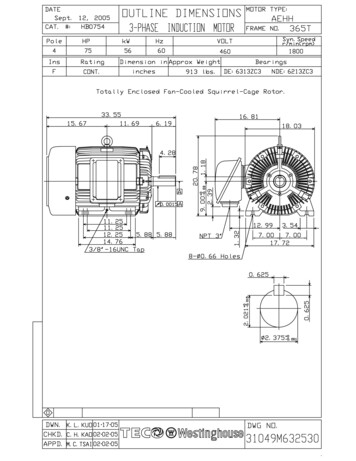
Content3-1 Basic configuration3-2 Configuration of computer connected and spare program cartridge.3-1
Chapter 3System Configuration3-1 Basic System Configuration -DC 24V -I1 I2 I3 I4 I5 I6 A1 A2Input 8 x DC(A1,A2 0 10V)DC 24VI1 I2 I3 I4 I5 I6 A1 A2 -I1 I2 I3 I4 I5 I6Input X1 X2 X3 X44 ACLInput 8 x DC(A1,A2 0 10V)N AC 100 240VRunRunQ2Output 4 x Relay / 8AOutput 4 x Relay / 8AOutput 4 x Relay / G2 10/12 Points:Blind Type 10HR-A 12HR-D 12HT-D 12HR-12D 10KR-A 12KR-D 12KT-D 12KR-12DI1 I2I3I4DC 24VI5I6I7I8 10CR-A 12CR-D 12CT-D 12CR-12DSG2 20 points:Expansion Type 20HR-A 20HR-D 20HT-D 20HR-12DOutput 8 x Relay / 8A -Q3I1 I2I3Q4I4Y3Y4I5Q5I6I7I8DC 24V 8ER-A 8ER-D 8ET-D 4AI Modbus Devicenet Profibus TCP/IPA1 A2 A3 A4Input 12 x DC(A1.A4 0 10V)Q2Q4Bare board Type(economical type)SG2-20HR-DQ1Q3SG2 expand I/O & COMM:Expansion Type -Q2Y2Q6I9Q7High-Speed Type 20VR-D 20VT-DQ8Blind Type 20KR-A 20KR-D 20KT-D 20KR-12DIA IB ICInput 8 x DCRunBare board Type (Economic) 20CR-A 20CR-D 20CT-D 20CR-12D20KT-DOutput 8 x Tra. / 0.5AT1T2T3T4T5T6T7T83-2
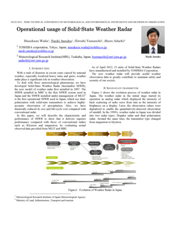
PCClient CablePDAClient Software232-USB converterPM05 (spare program cartridge3-2 Configuration for computer Connection and Spare Program Cartridge(1) Link the computer and SG2 with Client Cable. Through the Client software, the computer isready to read and write the programs contained in SG2 and oversee on line operation in SG2. (Seethe figure below)ComputerFigure 3-2-1Note: SG2 PDA software suits PDA based on WIN CE and matching with the connectorSG2-PL02, Such as HP2200, 2190 and 2210, etc.(2) Plug PM05 into the SG2 which is able to load and recover the programs from the PM05.(See the figure below)3-3
Figure 3-2-23-4
Chapter 4Installation4.1 Installation EnvironmentThe SG2 PLC is prohibited to be installed under the following environments: The ambient temperature is beyond -20 55 . The relative humidity exceeds 5 90%. Area is brimful of dust, salt and iron powder. Under direct sunshine. The environment is subject to frequent vibration and impact. The area contains erosive and inflammable gases susceptible to fire. The area is abundant of volatile oil gas, organic solvent, ammonia, electrolytic gas. Poor ventilation or close to heating source.4.2 Installation and wiring methodWarn:Such product users should have special skill about PLC system. Only the personsqualified are access to control, install and use the products.The operator and the equipment will be damaged if neglect such warning.Precaution for Wiring The I/O signal wire shall not be routed in parallel to the power wire or placed in thesame tray. Adopt 0.75-3.5mm2 cable as the external wire. Apply 4 6kgf.cm torques to tighten the lock screws.4-1
4-2-1H-TYPE PRODUCTS:SG2-12H#-D //12H#-12DSG2-20##-D WARN:Unintentional equipment operation.The application of this product requires know-how in design and program of controlsystem. Only persons qualified are allowed to program, install and apply this product.Failure to follow this instruction will result in death, serious injury or equipmentdamage. -DC 24VI1I2I3I4I5I6 A1 A2Input 8 x DC(A1,A2 0 10V)SG2-12HR-DOutput 4 x Relay / 8AQ1Q2Q3Q4① - Power supplyterminals② - LCD display③ - Input terminals④ - Retractablemounting feet⑤ - Delete key⑥ - Selection key⑦ - Directionkeys(left/right/up/down)⑧ - Ok key⑨ - Escape key⑩ - EEPROMcartridge or PC cableconnection- Output terminals -I1 I2 I3DC 24VI4I5 I6I7 I8 -DC V -I1 I2 I3I1 I2I4I5 I6I5 I6 A1 A2I7A1 A2 A3 A4I8INPUTL NAC .VAC .VI4InputDC VL NI3I1 I2 I3I1 I2I3I4I5I6Input .I4I5 I6I7I8I9IA IB ICINPUT .A1 A2 A3 A4Input 12 x DC(A1.A4 0 10V)SG2-20HR-DOutput 8 x Relay / 8AQ1Q2Q3Q4Q5Q6Q7Q84-2
NGER:HAZARDOUS VOLTAGECut off all power before maintenance.Electric shock will result in death or serious injury.Input 12/24V DC: - -A1 A2I1 I2 I3 I4 I5 I6 A1 A2DC VSG2-12H# -DSG2-12H# -12DInputA1 A3A2 A4 - -DC VI1 I2 I3I4I5 I6 I7 I8A1 A2 A3 A4INPUTSG2-20## -DSG2-20## -12D4-3
- I1 I2 I3DC VI4 I5A1 A2 A3 A4I6 A1 A2InputInput 24V AC or 100 240V AC:L NAC .VL NI1 I2 I3 I4 I5 I6Input .I1 I2 I3 I4AC .VSG2-10HR-A/10HR-24AI5 I6 I7 I8I9 IA IB ICINPUT .SG2-20HR-A/20HR-24AOutput (Relay):Output 4 x Relay / 8AQ1Q2Output 8 x Relay / 8AQ3Q4Q1Q2Q3Q4Q5Q6Q7Output (Transistor):OUTPUT 4 x TR / 0.5A Q1- Q2-OUTPUT 8 x TR / 0.5A Q3- Q4- Q1- Q2- Q3- Q4- Q5- Q6- Q7- Q8-4-4Q8
I/O link or Remote I/O:(Only products, SG2-20VR-D/20VT-D/20VR-12D/20VT-12D are available.)A1 A2 A3 A4SABA1 A2 A3 A4SRS485ABA1 A2 A3 A4ASRS485BRS485①-1A quick-blowing fuse, circuit-breaker or circuit protector②-Surge absorber (36V DC)③-Surge absorber (400V AC)④-Fuse, circuit-breaker or circuit protector⑤-Inductive load⑥-Only short circuit the first product and the last product⑦-Comply with standard : EIA RS-485.When I/O link, the net can connect 8 productsin max.(ID:1 8).When Remote I/O is available, it only can connect 2 products inmax.(MASTER & SLAVE)。Communicate with SG2 CLIENT Software:2 -DC 24V I1 I2 I3 I4 I5 I6 A1 A2Input 8 x DC(A1,A2 0 10V)-DC 24V- I1 I2 I3 I4 I5 I6 A1 A2Input 8 x DC(A1,A2 0 10V)DC 24VI1 I2 I3 I4 I5 I6 A1 A2Input 8 x DC(A1,A2 0 10V)I1 [ T1[ T2T1 [Q1SG2-12HR-DSG2-12HR-DSG2-12HR-DOutput 4 x Relay / 8AOutput 4 x Relay / 8A1Q1Q2Q3Q4Q1Q2Q1Q2Q3Q44PCSG2 CLIENTV.3Communicate with PM05:4-5
3 -DC 24VI1 I2I3I4I5 I6 A1 A2Input 8 x DC(A1,A2 0 10V)-DC 24VI1 I2I3I4I5- I6 A1 A2Input 8 x DC(A1,A2 0 10V)DC 24VI1 I2I3I4I5I6 A1 A2Input 8 x DC(A1,A2 0 10V)I1 [ T1[ T2T1 [Q1SG2-12HR-DSG2-12HR-DOutput 4 x Relay / 8ASG2-12HR-DOutput 4 x Relay / 8A1Q1Q2Q3Q4Q1Q2PM05Output 4 x Relay / 8AQ3I1 [ T1[ T2T1 [Q1Q42XXXXQ1Q2Q3Q444-6
4-2-2 K-TYPE PRODUCTS:SG2-12K#-D //12K#-12DSG2-20K#-D WARN:Unintentional equipment operation.The application of this product requires know-how in design and program of controlsystem. Only persons qualified are allowed to program, install and apply this product.Failure to follow this instruction can result in death, serious injury or equipmentdamage.L NI1 I2 I3 I4 I5 I6AC 100 240VINPUT 6 x ACRUNSG2-10KR-AOUTPUT 4 x RELAY / 8AQ1Q2Q3Q4①-Power supplyterminals②-Retractablemounting feet③-Input terminals④-Voltage/Operating modegreen signalingLED⑤-EEPROMcartridge or PCcable connection⑥-Relay outputterminals- I1DC V -I1I2I3I4NI5I1A C .VA C .VI4I5I6A1 A2I6I7I8A1 A2 A3 A4IN P U TLNI3InputDC VLI2I1I2I2I3I4I5I6Input .I3I4I5I6I7I8I9IAIBIN P U T .4-7IC
L NL NI1 I2 I3 I4 I5 I6AC 100 240VI1 I2 I3 I4AC 100 240VINPUT 6 x ACI9 IA IB ICINPUT 12 x ACRUNRUNSG2-20KR-ASG2-10KR-AOUTPUT 4 x RELAY / 8AQ1I5 I6 I7 I8Q2OUTPUT 8 x RELAY / 8AQ3Q4Q1Q2Q3Q4Q5Q6Q7Q8L NI1 I2AC 100 240VI3I4I5 I6INPUT 6 x ACRUNSG2-10KR-AOUTPUT 4 x RELAY / lb-in5.4DANGER:HAZARDOUS VOLTAGECut off all power before maintenance.Electric shock will result in death or serious injury.4-8
Input 12/24V DC: - -A1 A2 -I1 I2 I3 I4 I5 I6 A1 A2DC VA1 A3A2 A4 -InputI1 I2 I3 I4DC 1 I2 I3 I4 I5 I6 A1 A2DC VA1 A2 A3 A4INPUTRUN I5 I6 I7 I8A1 A2 A3 A4InputRunInput 24V AC or 100 240V AC:L NAC .VI1 I2 I3I4 I5 I6Input .L NAC .VRunSG2-10KR-A /10KR-24AI1 I2 I3I4I5 I6I7I8I9IA IB ICINPUT .RunSG2-20KR-A/20KR-24A4-9
Output (Relay):Output 4 x Relay / 8AQ1Q2Output 8 x Relay / 8AQ3Q4Q1Q2Q3Q4Q5Q6Q7Q8Output (Transistor):OUTPUT 4 x TR / 0.5A Q1- Q2-OUTPUT 8 x TR / 0.5A Q3- Q4- Q1- Q2 - Q3- Q4- Q5- Q6- Q7- Q8-- 1A quick-blowing fuse, circuit-breaker or circuit protector- Surge absorber (36V DC)- Surge absorber (400V AC)- Fuse, circuit-breaker or circuit protector- Inductive loadCommunicate with SG2 CLIENT Software:2 -DC 24V I1 I2 I3 I4 I5 I6 A1 A2Input 8 x DC(A1,A2 0 10V)-DC 24VI1 I2 I3 I4 I5 I6 A1 A2Input 8 x DC(A1,A2 0 10V)-DC 24VI1 I2 I3I4 I5 I6 A1 A2Input 8 x DC(A1,A2 0 10V)RunRunRunSG2-12KR-DI1 [ T1[ T2T1 [Q1SG2-12KR-DRunSG2-12KR-DOutput 4 x Relay / 8AOutput 4 x Relay / 8A1Q1Q2Q3Q4Q1Q2Q1Q2Q3Q4PCSG2 CLIENTV.3- Unplug the PM05 cartridge first.- Don’t electrify until the CLIENT CABLE is connected.- Execute SG2 CLIENT software online.4-104
- Plug the PM05 cartridge again after confirming the program is transferred.Communicate with PM05:3 -DC 24V I1 I2 I3 I4 I5 I6 A1 A2Input 8 x DC(A1,A2 0 10V)-DC 24VRunDC 24VOutput 4 x Relay / 8ASG2-12KR-DSG2-12KR-DOutput 4 x Relay / 8AOutput 4 x Relay / 81Q1Q2Q3Q4I1 I2 I3Q1Q2Q3I1 [ T1[ T2T1 [Q1I4 I5 I6 A1 A2Input 8 x DC(A1,A2 0 10V)I1 [ T1[ T2T1 [Q1RunSG2-12KR-D- I1 I2 I3 I4 I5 I6 A1 A2Input 8 x DC(A1,A2 0 10V)2Q4XXXXQ1Q2RunPM05Q3RunQ44- Unplug the PM05 cartridge first.- Please do not electrify the product before PM05 is plugged.- Electrify the product, the program will automatically transferred & executed.- Following is what the LED working in different state description:RunDiagnose4-11
4-2-3 C-TYPE PRODUCTS:SG2-12C#-D //12C#-12DSG2-20C#-D WARN:Unintentional equipment operation.The application of this product requires know-how in design and program of controlsystem. Only persons qualified are allowed to program, install and apply this product.Failure to follow this instruction will result in death, serious injury or equipmentdamage.- Q1I1 I2I3I4Q2I5I6 A1 A2Q3Q4① - Input terminals② - Power supplyterminals③ - EEPROMcartridge or PC cableconnection④ - Retractablemounting feet⑤ - Output terminals L Q1-I1 I2 I3 I4Q2I5 I6 A1 A2Q3Q4LI1 I2 I3NQ1Q2Q3I4I5 I6Q4I7I8Q5I9-N -I1 I2I3LNI1 I2I3I1 I2I4I3I4I5I5 I6I7I8I1 I2 I3I4I5 I6I7I8I6 A1 A2A1 A2 A3 A4I4I5 I6I9IA IB ICQ6Q7Q84-12IA IB IC
-I1 I2 I3Q12Q2I4 I5 I6 A1 5.4DANGER:HAZARDOUS VOLTAGECut off all power before maintenance.Electric shock will result in death or serious injury.Input 12/24V DC: - -A1 A2I1 I2 I3SG2-12C# -DSG2-12C# -12DI4 I5 I6 A1 A2A1 A3A2 A4 - -I1 I2 I3I4I5 I6 I7 I8A1 A2 A3 A4SG2-20C# -DSG2-20C# -12D4-13
- I1 I2 I3I4 I5 I6 A1 A2A1 A2 A3 A4Input 24V AC or 100 240V AC:LNI1 I2I3I4I5I6LSG2-10CR-A/10CR-24ANI1 I2I3I4I5I6I7I8I9IA IB ICSG2-20CR-A/20CR-24AOutput (Relay):Q1Q2Q3Q4Q1Q2Q3Q4Q5Q6Q7Q8Output (Transistor): Q1 - Q2 - Q3 - Q4 - Q1 - Q2 - Q3 - Q4 - Q5 - Q6 - Q7 -①-1A quick-blowing fuse, circuit-breaker or circuit protector4-14 Q8 -
②-Surge absorber (36V DC)③-Surge absorber (400V AC)④-Fuse, circuit-breaker or circuit protector⑤-Inductive loadCommunicate with SG2 CLENT Software:1 -I1 I2 I3I4 I5 I6 A1 A2 -I1 I2 I3I4I5 I6 A1 A22PCQ1Q2Q3Q4Q1Q2Q3SG2 CLIENTV.Q4- Don’t electrify until the CLIENT CABLE is connected.- Connect the CLIENT CABLE.- Execute SG2 CLIENT software online.4-153
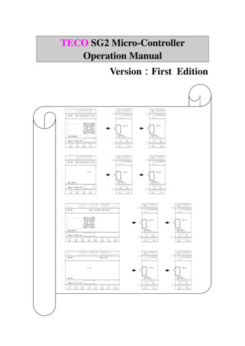
4-2-4 E typeE-TYPE series productSG2-8ER-D/8ET-DSG2-8ER-ASG2-4AIX1 X2 X3 X4Input4 ACL①Power supplyterminals②Retractablemounting feet③Input terminal④Voltage/Operatingmode green signalingLED⑤Press-button⑥Relay outputterminals⑦ConnectorNAC 100 240VRunSG2-8ER-AOutput 4 x Relay / 8AY1Y3Y2SG2-4AII1 V1 C1 PEINPUT X1 X2 X3 X44 DC - -DC 24vDCRUNINPUT X1 X2 X3 X44 ACLNACSG2-4AIInput 4 x (0.10V/0.20mA)I2 V2 C2PEI3 V3 C3 I4 V4 C4Y4Uni t : mm ( 1i nch 25. 4mm)INPUT X1 X2 X3 X44 ACLNAC 100 240VRUNSG2-8ER-AOutput 4 x Relay / 8AY1Y3Y2Y44-16
Input X1 X2 X3 X44 ACLNAC 100 240VRunSG2-8ER-AOutput 4 x Relay / 8AY1Y3- I1 I2DC 24VI3I4I5Y2Y4Input X1 X2 X3 X44 ACI6 A1 A2LInput 8 x DC(A1,A2 0 10V)NAC 100 240VRunSG2-8ER-ASG2-12HR-DOutput 4 x Relay / 8AOutput 4 x Relay / 8AQ1 -DC 24VI1 I2 I3 I4Q2I5 I6 A1 A2Input 8 x DC(A1,A2 0 10V)Y1Q3Y3Q4Y2Y4Input X1 X2 X3 X44 ACLN AC 100 240VRunSG2-8ER-ASG2-12HR-DOutput 4 x Relay / 8AOutput 4 x Relay / 8AQ1Q2Y1Q3Q4Y3Y2Y44-17
nger:Cut off all the power supply before maintenance.Or operator will be damaged for electric shock.1) Input 24V DC4-18
PEPEI1 V1 C1 PE -I1 V1 C1 PE -DC 24vDC 24vRUNRUNSG2-4AISG2-4AIInput 4 x (0.10V/0.20mA)Input 4 x (0.10V/0.20mA)I2 V2 C2I2 V2 C2PEI3 V3 C3 I4 V4 C4I3 V3 C3 I4 V4 C4PEPEPEPEPEPEPE2) Input 100 240V AC:3) Output(Relay):4-19
SG2-8ER-AOutput 4 x Relay / 8AY1Y3Y2Y44) Output (Transistor):SG2-8ET-DOUTPUT 4 x TR/0.5A Y1 Y3 - Y2 Y4 -- 1A quick-blowing fuse, circuit-breaker or circuit protector- Surge absorber(36V DC)- Surge absorber(400V AC)- Fuse, circuit-breaker or circuit protector- Inductive loadNote: When Relay output connects with AC inductance load, please parallelconnect with a surge absorber, while connects with DC inductance load, parallelconnect with a rectifying diode with the negative withstand voltage over 5 10 timesof the load voltage and positive curre
TECO SG2 Micro-Controller Operation Manual VersionꅇFirst Edition Y3 Output 4 x Relay / 8A SG2-8ER-A AC 100 240V Run AC 100 240V Run Input X1 X2 4 AC - IC DC 24V Input 8 x DC T5 T6 Run T3 T4 20KT-D T1 T2 Output 8 x Tra. / 0.5A Y3 Y1 Output 4 x Relay / 8A LN T7 T8 SG2-8ER-A