Transcription
CH A P T E R1OverviewThis chapter provides an overview of the Cisco Nexus 5000 Series switches, which include the CiscoNexus 5000 Platform switches and the Cisco Nexus 5500 Platform switches. The overview of each ofthese switches includes information on the expansion modules, power supplies, and fan modules that youcan include with them.This chapter includes the following sections: Cisco Nexus 5500 Platform Switches, page 1-1 Cisco Nexus 5000 Platform Switches, page 1-29Cisco Nexus 5500 Platform SwitchesThe Cisco Nexus 5500 Platform supports the following application scenarios, many of which require theinstallation of other products: As an access-layer switch, it can be used purely as a 1- and 10-Gigabit Ethernet switch,consolidating 10 Gigabit Ethernet connections into a smaller number of server connections trunkedto the aggregation layer. As a smaller-scale aggregation switch, it can be used as a Layer 3 1- and 10-Gigabit Ethernet switch,consolidating multiple 1- and 10-Gigabit Ethernet connections from a data center access layer. In conjunction with the Cisco Nexus 2248T GE Ethernet Fabric Extender, the Cisco Nexus 5500Platform can be a high-density 1-Gigabit Ethernet switching system, consolidating more than 900Gigabit Ethernet connections within a single management plane. In conjunction with the Cisco Nexus 2232T 10GE Fabric Extender, it can be a high-densityswitching system, consolidating more than 600 10-Gigabit Ethernet connections within a singlemanagement plane. In conjunction with the Cisco Nexus 2224TM 10GE Fabric Extender, it can be a high-densityswitching system, consolidating more than 600 10-Gigabit Ethernet connections within a singlemanagement plane As a rack-level I/O consolidation platform, the switch carries Ethernet traffic from servers to theaggregation layer and carries FC traffic to existing Fibre Channel SANs. As a crucial element in data center I/O consolidation, the switch enables I/O consolidation at theaccess layer and provides interoperability with the Cisco Nexus 5500 Platform and otherstandards-based products.This section describes the Cisco Nexus 5500 Platform switches and contains these sections: Cisco Nexus 5596UP Switch, page 1-2Cisco Nexus 5000 Series Hardware Installation Guide1-1
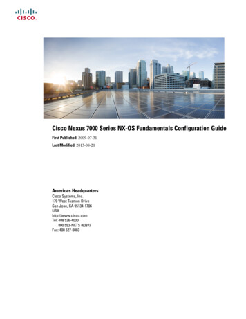
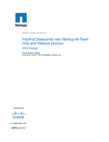
Chapter 1OverviewCisco Nexus 5500 Platform Switches Cisco Nexus 5596T Switch, page 1-12 Cisco Nexus 5548UP and 5548P Switches, page 1-17Cisco Nexus 5596UP SwitchThis section describes the Cisco Nexus 5596UP switch and its components. This section includes thefollowing topics: Features, page 1-2 Chassis, page 1-2 Expansion Modules, page 1-4 Ports, page 1-7 Power Supply, page 1-8 Fan Module, page 1-10 Transceivers, page 1-11FeaturesThe Cisco Nexus 5596UP switch is a top-of-rack, 10-Gigabit Ethernet and Fibre channel over Ethernet(FCoE) switch offering up to 1920 Gigabit throughput and up to 96 ports. The switch has 48 1- and10-Gigabit Ethernet and FCoE ports and three expansion slots. As a top-of-rack switch, all the serversin the rack connect to the Cisco Nexus 5596UP switch, and it connects to the LAN or SAN.The Cisco Nexus 5596UP switch has the following features:Note 48 fixed 1- and 10-Gigabit Ethernet server connection ports on the back of the switch Three slots on the back of the switch for optional expansion modules, which can be either a 16-port10-Gigabit generic expansion module 2 (GEM2) or a layer 3 GEM2 Two slots on the front of the switch for hot swap-capable power supplies, which providefront-to-back airflow for cooling (the Cisco Nexus 5596T and 5596UP switches alternativelysupport back-to-front [port-side intake] airflow) Four slots on the front of the switch for hot swap-capable fan modules. Layer 2 or Layer 3 I/O modules One USB port on the front of the switchHot swapping of normal air flow fans and power supplies with reverse airflow fans and power suppliesis not supported on the Cisco Nexus 5000 switches. Hot swapping of fans and power supplies is onlysupported if they are replaced with the same direction parts.ChassisThe Cisco Nexus 5596UP chassis is 2 RU or 3.47 inches (8.8 cm) tall, 17.3 inches (43.9 cm) wide, and29.5 inches (74.9 cm) deep. It is designed to be mounted in a standard 19-inch wide rack. The front ofthe switch, shown in Figure 1-1, has a USB port, four Ethernet and ports (two cross-connect ports, onemanagement port, and one console port), two power supplies, and four fan modules.Cisco Nexus 5000 Series Hardware Installation Guide1-2
OverviewCisco Nexus 5500 Platform SwitchesFigure 1-1Front View of the Cisco Nexus 5596UP Switch2134237867561USB port4System status LED2Management and console ports (two RJ-45 Ethernet connectorports on the left, a RJ-45 network management connector on theupper right, and a console connector on the lower right)5Two power supplies3Identifier LED6Four fan modulesThe management and console ports are in a 2 x 2 stacked RJ-45 jack. Figure 1-2 shows a close-up viewof these ports. For information about the connector port LEDs, see Table D-1 on page D-2.Figure 1-2Management and Console Ports2341239021Chapter 15Cisco Nexus 5000 Series Hardware Installation Guide1-3
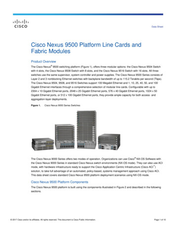
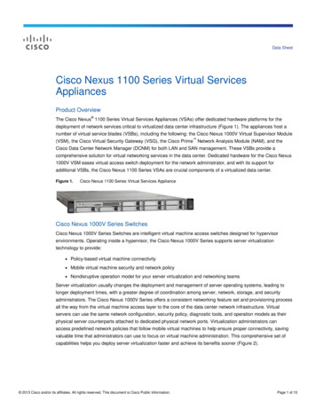
Chapter 1OverviewCisco Nexus 5500 Platform Switches1Internal cross-connect ports4Network management port2Link LED (left LED)5Console port3Activity LED (right LED)The rear of the Cisco Nexus 5596UP chassis, shown in Figure 1-3, has 48 fixed 10-Gigabit Ethernet dataports on the bottom and three slots for optional expansion modules on top.Figure 1-3Rear View of the Cisco Nexus 5596UP Switch11123Note23786641Expansion modules, shown here with three16-port Universal GEM2 modules (can alsohave Layer 3 GEM2 modules)3System status LED2Identifier LED448 fixed 1- and 10-Gigabit Ethernet portsThe L1/L2/Mgmt1 ports are not usable. They are disabled at this time.Expansion ModulesExpansion modules allow the Cisco Nexus 5596UP switch to be configured as cost-effective 10-GigabitEthernet switches and as I/O consolidation platforms with native Fibre Channel connectivity.The Cisco Nexus 5596UP switch has three slots that can be used for the following optional expansionmodules: 4-port QSFP expansion module 16-port Universal (Fibre Channel and Ethernet) GEM (N55-M16UP) that provides 8-, 4-, 2-, or1-Gbps Fibre Channel and 1- or 10-Gigabit Ethernet portsCisco Nexus 5000 Series Hardware Installation Guide1-4
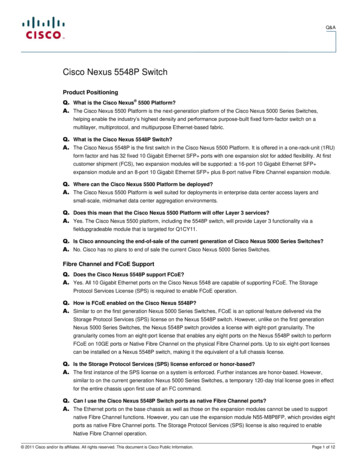
Chapter 1OverviewCisco Nexus 5500 Platform Switches Layer 3 GEMs (N55-M160L3 and N55-M160L3-V2) provide 160 Gbps of Layer 3 services. TheN55-M160L3-V2 uses a newer version of the Layer 3 ASIC that enables higher table sizes in a futuresoftware release from 8K host entries to 16K host entries or from 4K multicast routes to 8Kmulticast routes (IPv4).You can hot swap the expansion modules during operations, except the Layer 3 GEMs. You must powerdown the switch before you can insert or remove the Layer 3 GEMs.This section includes the following topics: 4-port QSFP GEM, page 1-5 16-port Universal GEM2, page 1-5 Layer 3 GEM, page 1-64-port QSFP GEMThe QSFP GEM (N55-M4Q), shown in Figure 1-4, is a generic expansion module (GEM) that provides16x10 Gigabit Ethernet SFP in a 4 x QSFP form factor. This module is a field-replaceable unit (FRU)that you can hot swap during operations.Figure 1-44-Port QSFP GEM16-port Universal GEM2The 16-port Universal GEM2, shown in Figure 1-5, has 16 8-, 4-, 2-, or 1-Gbps Fibre Channel or 1- and10-Gigabit Ethernet ports. This module is a field-replaceable unit (FRU) that you can hot swap duringoperations.Cisco Nexus 5000 Series Hardware Installation Guide1-5
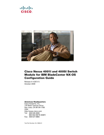
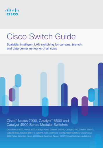
Chapter 1OverviewCisco Nexus 5500 Platform SwitchesFigure 1-516-Port Universal GEM213423797721Status LED316 ports supporting 8-, 4-, 2-, or 1-Gbps transceivers or 1- and10-Gigabit transceivers2Eject lever4Captive screw that locks the eject lever in a closed positionSee Figure 1-7 on page 1-7 to see how ports are grouped and numbered on the Fibre Channel plusEthernet expansion module.Layer 3 GEMThe Layer 3 GEMs (N55-M160L3 and N55-M160L3-V2), shown in Figure 1-6, provide 160 Gbps ofLayer 3 services. The expansion modules are field-replaceable units (FRUs). The N55-M160L3-V2 usesa newer version of the Layer 3 ASIC that enables higher table sizes in a future software release from 8Khost entries to 16K host entries or from 4K multicast routes to 8K multicast routes (IPv4).The Layer 3 GEMs are not hot swappable and can be inserted and removed only when the switch ispowered down.Cisco Nexus 5000 Series Hardware Installation Guide1-6
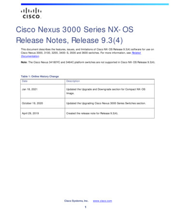
Chapter 1OverviewCisco Nexus 5500 Platform SwitchesFigure 1-6Layer 3 GEM21237976231Status LED32Ejector leverCaptive screw that locks the eject lever in aclosed positionPortsEach port on the Cisco Nexus 5596UP switch is numbered, and groups of ports are numbered based ontheir function. The ports are numbered top to bottom and left to right. The 48 fixed ports support 8-, 4-,2-, or 1-Gbps Fibre Channel transceivers and 1- or 10-Gigabit Ethernet transceivers.Figure 1-7 shows how ports are numbered and grouped by function for both the fixed ports and the FibreChannel plus Ethernet expansion module ports.Figure 1-7Port Numbering of Fixed Ports and Fibre Channel Plus Ethernet Expansion Module 84042444648237978121Port numbering for the 16-port GEM2Port numbering for the 48 fixed portsCisco Nexus 5000 Series Hardware Installation Guide1-7
Chapter 1OverviewCisco Nexus 5500 Platform SwitchesPower SupplyThe Cisco Nexus 5596UP uses a front-end power supply. The chassis has slots for two power supplies.The Cisco Nexus 5596UP switch is fully functional with one power supply, but you can include a secondpower supply for power redundancy.Table 1-1 lists the power supplies that you can order with the Cisco Nexus 5596UP and 5596T switches.Table 1-1Power Supplies for the Cisco Nexus 5596UP and 5596T switchesPart NumberPower SupplyN55-PAC-1100WCisco Nexus 5596UP PSU Port-Side Exhaust Airflow module, A/C,100-240V, 1100WN55-PAC-1100W( )Cisco Nexus 5596UP PSU Port-Side Exhaust Airflow module spare, A/C,100-240V, 1100WN55-PAC-1100W-BCisco Nexus 5596UP/5596T PSU Port-Side Intake Airflow module, A/C,100-240V, 1100WN55-PAC-1100W-B( )Cisco Nexus 5596UP/5596T PSU Port-Side Intake Airflow module spare,A/C, 100-240V, 1100WN55-PDC-1100WCisco Nexus 5596UP/5596T PSU DC Port-Side Exhaust module, 1100 WN55-PDC-1100W( )Cisco Nexus 5596UP/5596T PSU DC Port-Side Exhaust module spare,1100 WNXA-PHV-1100WCisco Nexus 5500/6000 Platinum HV-AC-DC PS, Port side Exhaust airflow,1100WNXA-PHV-1100W( )Cisco Nexus 5500/6000 Platinum HV-AC-DC PS, Port side Exhaust airflow,1100W, spareNXA-PHV-1100W-BCisco Nexus 5500/6000 Platinum HV-AC-DC PS, Port side Intake airflow,1100WNXA-PHV-1100W-B( ) Cisco Nexus 5500/6000 Platinum HV-AC-DC PS, Port side Intake airflow,1100W, spareNoteFront to Back (FAF) Airflow and DC Power Supply is now supported for the Cisco Nexus 5596T. Fordetails see the Cisco Nexus 5500 Datasheet.Figure 1-8 shows an AC power supply. For more information on the LEDs, see Table D-1 on page D-2.Cisco Nexus 5000 Series Hardware Installation Guide1-8
OverviewCisco Nexus 5500 Platform SwitchesFigure 1-8AC Power Supply for the Cisco Nexus 5596UP Switch13237868Chapter 121Failure (top) and Power (bottom) LEDs2Handle3Release leverFigure 1-9 shows the NXA-PAC-1100W.Figure 1-9NXA-PAC-1100WFigure 1-10 shows the NXA-PAC-1100W-BCisco Nexus 5000 Series Hardware Installation Guide1-9
Chapter 1OverviewCisco Nexus 5500 Platform SwitchesFigure 1-10NXA-PAC-1100W-BFigure 1-11 shows NXA-PDC-1100WFigure 1-11NoteNXA-PDC-1100WNever leave a power supply slot empty. If you remove a power supply, replace it with another one. If youdo not have a replacement power supply, leave the non functioning one in place until you can replace it.Fan ModuleThe Cisco Nexus 5596UP switch has four fan modules. Although the switch can function when a fanstops functioning within a fan module, if a whole fan module stops functioning, you must replace the fanmodule. The Cisco Nexus 5596UP supports the reverse air flow fan tray (N5596UP-FAN-B).Figure 1-12 shows a fan module.Cisco Nexus 5000 Series Hardware Installation Guide1-10
Chapter 1OverviewCisco Nexus 5500 Platform SwitchesCautionAll of the power supply and fan modules in the same chassis must use the same airflow direction or anerror will occur with possible over heating and shut down of the switch. If you power up the switch withmore than one airflow direction, you must power down the switch and replace the modules with thewrong airflow direction (modules not taking in coolant air from the cold aisle) before powering up theswitch.Figure 1-12Cisco Nexus 5596 Fan Module1239022231Captive screw2Status LED3HandleThe bicolor status LED indicates fan tray health. Green indicates normal operation, while amberindicates a fan failure. For more information about LEDs, see Table D-1 on page D-2.TransceiversThe Cisco Nexus 5596 switch supports both SFP and SFP Ethernet transceivers and SFP Fibre Channeltransceivers.This section includes the following topics: SFP Transceivers, page 1-11 SFP Copper Cables, page 1-12 SFP Fibre Channel Transceivers, page 1-12 CWDM Optics, page 1-12SFP TransceiversThe enhanced SFP 10-Gigabit Ethernet transceiver module is a bidirectional device with a transmitterand receiver in the same physical package. It has a 20-pin connector on the electrical interface andduplex LC connector on the optical interface.The Cisco Nexus 5596 supports the SFP-10G-SRtransceiver.Cisco Nexus 5000 Series Hardware Installation Guide1-11
Chapter 1OverviewCisco Nexus 5500 Platform SwitchesModelDescriptionSFP-10G-SR10-Gigabit Ethernet—short range SFP moduleSFP Copper CablesCopper cables are available for use with the 10-Gigabit Ethernet SFP module. The cables come in thefollowing lengths: 1 m, 30 AWG 3 m, 28–30 AWG 5 m, 26–28 AWGModelDescriptionSFP-H10GB-CU1M10GBASE-CU SFP Cable (1 meter)SFP-H10GB-CU3M10GBASE-CU SFP Cable (3 meters)SFP-H10GB-CU5M10GBASE-CU SFP Cable (5 meters)SFP Fibre Channel TransceiversThe Cisco Nexus 5596 switch also supports the following SFP Fibre Channel transceiver:ModelDescriptionDS-SFP-FC4G-SW4-, 2-, or 1-Gbps Fibre Channel—Shortwavelength SFP moduleCWDM OpticsThe Cisco Nexus 5596 switch also supports the following CWDM optics:ModelDescriptionDS-CWDM4G1470 1470 nm CWDM 1/2/4-Gbps Fibre Channel SFPDS-CWDM4G1610 1610 nm CWDM 1/2/4-Gbps Fibre Channel SFPCisco Nexus 5596T SwitchThe Nexus 5596T is based on the same ASIC and chassis as the 5596UP. The Nexus 5596T switch is a2RU switch, with 32 fixed ports of 10G BaseT and 16 fixed 10G Unified ports, which support (Ethernet,FC, FCoE). All the existing GEMs supported on the Nexus 5500 switches will be supported on the Nexus5596T. In addition, the Nexus 5596T will also support the new 12 port 10G BaseT expansion module.With this module, you can use the Nexus 5596T to deploy up to 68 ports of 10G BaseT in a 2RU formfactor. The 10G BASE-T ports support FCoE up to 30m distance with Category 6a and Category 7 cable.Cisco Nexus 5000 Series Hardware Installation Guide1-12
Chapter 1OverviewCisco Nexus 5500 Platform SwitchesThis switch supports both front-to-back (port-side exhaust) and back-to-front (port-side intake) airflow.The 12 port 10G BaseT module will be supported on the Nexus 5596T chassis. The orderabilityinformation is as follows: N5K-C5596T-FA: Nexus 5596T 2RU, 2PS/4Fans, 32x10GT/16xSFP Fixed Ports N55-M12T: Nexus 5500 Module 12p 10GTThis section describes the Cisco Nexus 5596T switch and its components. This section includes thefollowing topics: Features, page 1-13 Chassis, page 1-13 Ports, page 1-15 Power Supply, page 1-16 Fan Module, page 1-16 Transceivers, page 1-16FeaturesThe Cisco Nexus 5596T switch is a 2RU switch, with 32 fixed ports of 10GBASE-T and 16 SFP fixedports. The switch also supports up to three expansion slots. The switch supports 10 Gigabit Ethernet(fiber and copper), Fibre Channel, and FCoE, offering up to 1920 Gbps of throughput and up to 96 ports.The switch supports unified ports on all SFP ports. The hardware for the 10GBASE-T ports is capableof supporting FCoE. FCOE on 10GBaseT ports is supported only for lengths less than or equal to 30m.The Cisco Nexus 5596T switch has the following features: 32 fixed ports of 10GBASE-T and 16 fixed ports of SFP on the back of the switch Three slots on the back of the switch for optional expansion modules Two slots on the front of the switch for hot swap-capable power supplies, which provideback-to-front (port-side exhaust) or front-to-back (port-side intake) airflow for cooling (this switchsupports only one direction of airflow at a time for all modules) Four slots on the front of the switch for hot swap-capable fan modules, which provide back-to-front(port-side exhaust) or front-to-back (port-side intake) airflow for cooling (this switch supports onlyone direction of airflow at a time for all modules). Layer 2 or Layer 3 I/O modules One USB port on the front of the switchChassisThe Cisco Nexus 5596T chassis is 2 RU or 3.47 inches (8.8 cm) tall, 17.3 inches (43.9 cm) wide, and29.5 inches (74.9 cm) deep. It is designed to be mounted in a standard 19-inch wide rack. The front ofthe switch is shown in Figure 1-13.Cisco Nexus 5000 Series Hardware Installation Guide1-13
Chapter 1OverviewCisco Nexus 5500 Platform SwitchesFigure 1-13Front View of the Cisco Nexus 5596T Switch2134237867561USB port4System status LED2Management and console ports (two RJ-45 Ethernet connectorports on the left, a RJ-45 network management connector on theupper right, and a console connector on the lower right)5Two power supplies3Identifier LED6Four fan modulesThe management and console ports are in a 2 x 2 stacked RJ-45 jack. Figure 1-2 shows a close-up viewof these ports. For information about the connector port LEDs, see Table D-1 on page D-2.The rear of the Cisco Nexus 5596T chassis, shown in Figure 1-14, has 32 fixed ports of 10GBASE-T and16 fixed ports of SFP . It also has up to three expansion slots.Figure 1-14Rear View of the Cisco Nexus 5596T Switch11124Cisco Nexus 5000 Series Hardware Installation Guide1-142378663
Chapter 1OverviewCisco Nexus 5500 Platform Switches1Expansion modules3System status LED2Identifier LED432 fixed ports of 10GBASE-T and 16 fixedports of SFP Expansion ModulesExpansion modules allow the Cisco Nexus 5596T switch to be configured as cost-effective 10-GigabitEthernet switches and as I/O consolidation platforms with native Fibre Channel connectivity.The Cisco Nexus 5596T switch has three slots that can be used for the following optional expansionmodules: Ethernet module that provides sixteen 1- or 10-Gigabit Ethernet and FCoE ports using the SFP interface Fibre Channel plus Ethernet module that provides eight 1- or 10-Gigabit Ethernet and FCoE portsusing the SFP interface, and eight ports of 8/4/2/1-Gbps native Fibre Channel connectivity usingthe SFP /SFP interface Unified port module that provides up to sixteen 1- or 10-Gigabit Ethernet and FCoE ports using theSFP interface or up to sixteen ports of 8/4/2/1-Gbps native Fibre Channel connectivity using theSFP and SFP interfaces. The use of 1- or 10-Gigabit Ethernet or 8/4/2/1-Gbps Fibre Channel on aport is mutually exclusive but can be selected for any of the 16 physical ports per module Ethernet module that provides twelve 10GBASE-T ports (N55-M12T). The hardware is FCoEcapableYou can hot swap the expansion modules during operations.PortsEach port on the Cisco Nexus 5596T is numbered, and groups of ports are numbered based on theirfunction. The ports are numbered top to bottom and left to right.Figure 1-15 shows how ports are numbered and grouped by function.Figure 1-15Port NumberingCisco Nexus 5000 Series Hardware Installation Guide1-15
Chapter 1OverviewCisco Nexus 5500 Platform SwitchesPower SupplyThe Cisco Nexus 5596T uses a front-end power supply. The chassis has slots for two power supplies.The Cisco Nexus 5596T switch is fully functional with one power supply, but you can include a secondpower supply for power redundancy.Table 1-1 lists the power supplies that you can order with the Cisco Nexus 5596UP and 5596T switches.NoteFront-to-Back (port-side exhaust) airflow and DC power supplies are now supported for the Cisco Nexus5596T. For details see the Cisco Nexus 5500 Datasheet.Figure 1-8, Figure 1-9, Figure 1-10, and Figure 1-11 show the power supplies that can be ordered withthe Cisco Nexus 5596UP and 5596T switches. For more information on the LEDs, see Table D-1 onpage D-2.NoteNever leave a power supply slot empty. If you remove a power supply, replace it with another one. If youdo not have a replacement power supply, leave the non functioning one in place until you can replace it.Fan ModuleThe Cisco Nexus 5596T switch has four fan modules. Although the switch can function when a fan stopsfunctioning within a fan module, if a whole fan module stops functioning, you must replace the fanmodule. The Cisco Nexus 5596T supports either front-to-back (port-side exhaust) or back-to-front(port-side intake) airflow (all fan and power supply modules must support the same direction of airflow).TransceiversThe Cisco Nexus 5596T switch supports both SFP and SFP Ethernet transceivers and SFP FibreChannel transceivers.This section includes the following topics: SFP Transceivers, page 1-16 SFP Copper Cables, page 1-17 SFP Fibre Channel Transceivers, page 1-17 CWDM Optics, page 1-12SFP TransceiversThe enhanced SFP 10-Gigabit Ethernet transceiver module is a bidirectional device with a transmitterand receiver in the same physical package. It has a 20-pin connector on the electrical interface andduplex LC connector on the optical interface.ModelDescriptionSFP-10G-SR10-Gigabit Ethernet—short range SFP moduleSFP-10G-LR( )10GBASE-LR SFP ModuleSFP-10G-ER( )10GBASE-ER-SFP ModuleCisco Nexus 5000 Series Hardware Installation Guide1-16
Chapter 1OverviewCisco Nexus 5500 Platform SwitchesSFP Copper CablesCopper cables are available for use with the 10-Gigabit Ethernet SFP module. The cables come in thefollowing lengths: 1 m, 30 AWG 3 m, 28–30 AWG 5 m, 26–28 AWGModelDescriptionSFP-H10GB-CU1M10GBASE-CU SFP Cable (1 meter)SFP-H10GB-CU3M10GBASE-CU SFP Cable (3 meters)SFP-H10GB-CU5M10GBASE-CU SFP Cable (5 meters)SFP Fibre Channel TransceiversThe Cisco Nexus 5596T switch also supports the following SFP Fibre Channel transceiver:ModelDescriptionDS-SFP-FC4G-SW4-, 2-, or 1-Gbps Fibre Channel—Shortwavelength SFP moduleCWDM OpticsThe Cisco Nexus 5596T switch also supports the following CWDM optics:ModelDescriptionDS-CWDM4G1470 1470 nm CWDM 1/2/4-Gbps Fibre Channel SFPDS-CWDM4G1610 1610 nm CWDM 1/2/4-Gbps Fibre Channel SFPCisco Nexus 5548UP and 5548P SwitchesThis section describes the Cisco Nexus 5548UP and 5548P switches and their components. The CiscoNexus 5548UP switch provides universal ports that support Ethernet and fibre channel over Ethernet(FCoE) connections. The Cisco Nexus 5548P switch provides ports that support Ethernet connections.Collectively, these switches are referred to as Cisco Nexus 5548 switches.This section includes the following topics: Features, page 1-18 Chassis, page 1-18 Expansion Modules, page 1-20 Data Ports, page 1-23 Power Supplies, page 1-23 Fan Modules, page 1-25Cisco Nexus 5000 Series Hardware Installation Guide1-17
Chapter 1OverviewCisco Nexus 5500 Platform Switches Transceivers and Cables, page 1-26FeaturesThe Cisco Nexus 5548UP switch is a 10-Gigabit Ethernet and FCoE switch that offers up to 960-Gbpsthroughput and up to 48 ports. The switch has 32 fixed 1- or 10-Gbps SFP Ethernet and FCoE ports andone expansion slot. The expansion slot supports GEMs that offer 16 10-Gigabit Ethernet ports, eight10-Gigabit Ethernet ports and eight 10-Gigabit FCoE ports, or 16 10-Gigabit Ethernet/FCoE ports. Thisswitch has an orange label with “Cisco Nexus 5548UP” above the Cisco logo on the front of the chassis.The Cisco Nexus 5548P switch is a 10-Gigabit Ethernet switch that offers up to 960-Gbps throughputand up to 48 ports. The switch has 32 fixed 1- or 10-Gbps SFP Ethernet and FCoE ports and oneexpansion slot. The expansion slot supports GEMs that offer 16 10-Gigabit Ethernet ports or eight10-Gigabit Ethernet ports and eight 10-Gigabit FCoE ports. This switch has a gray label with “CiscoNexus 5548P” above the Cisco logo on the front of the chassis.As a top-of-rack switch, all the servers in the rack connect to the Cisco Nexus 5548UP or Cisco Nexus5548P switch, and it connects to the LAN or SAN.The Cisco Nexus 5548UP and 5548P switches have the following features: One slot on the back of the switch for a Generic Expansion Module (GEM). Two slots on the frontof the switch for hot swap-capable power supplies. Two slots on the front of the switch for hot swap-capable fan modules. You can insert four fans permodule, which gives you a total of eight fans. One slot at the front of the switch for a USB port. Front-to-back (port-side exhaust) cooling that supports efficient data center hot and cold-aisledesigns. The Cisco Nexus 5548UP alternatively supports back-to-front (port-side intake) cooling(all fan and power supply modules in the same chassis must support the same direction of airflow).ChassisThe Cisco Nexus 5548 switch chassis is 1 RU, 1.72 inches (4.4 cm) tall, 17.3 inches (43.9 cm) wide, and29.5 inches (74.9 cm) deep. It is designed to be mounted in a standard 19-inch (48.26 cm) rack. Theswitch has two power supplies and two fans modules on the front of the switch. The switch also has oneUSB port (usb1:) at the front of the switch. This external USB flash memory is installed in a supervisormodule used for storing image files, configuration files, and other miscellaneous files. You can createdirectories on external flash memory and navigate through these directories. You can also create andaccess files.The usb1: port usage on the Cisco Nexus 5548 switch is the same as that on other Cisco NX-OS devices.(For details, see the chapter, “Using the Device File Systems, Directories, and Files” in the NX-OSFundamentals Configuration Guide for your software release.)Thirty-two fixed 10-Gigabit Ethernet ports and expansion modules are at the rear of the switch. The frontof the switch has an indicator LED, management ports, 2 fan modules and 2 power supplies as shown inFigure 1-16.Cisco Nexus 5000 Series Hardware Installation Guide1-18
OverviewCisco Nexus 5500 Platform SwitchesFigure 1-16Cisco Nexus 5548 Switch Front View1234239197Chapter 151ID LED4Two fan modules2Status LED5Two power supplies3Management (10/100/1000) ports, console port, and USB portThe rear of the Cisco Nexus 5548 switch chassis has 32 fixed 10-Gigabit ports and 1 slot for an optionalexpansion module. On the Cisco Nexus 5548UP switch, the 32 fixed ports are 10-Gigabit Ethernet andFCoE ports (port numbering is shown with an orange label). On the Cisco 5548P switch, the 32 fixedports are 10-Gigabit Ethernet ports (port numbering is shown with a gray label). Figure 1-17 shows therear of the Cisco Nexus 5548 switch.Cisco Nexus 5000 Series Hardware Installation Guide1-19
Chapter 1OverviewCisco Nexus 5500 Platform SwitchesFigure 1-17Cisco Nexus 5548 Switch Rear View124Note1ID LED332 fixed 10-Gigabit Ethernet/FCoE ports (Cisco Nexus 5548UP) or32 fixed 10-Gigabit Ethernet ports (Cisco Nexus 5548P)2Status LED4Expansion module2391983The L1/L2/Mgmt1 ports are not usable. They are disabled at this timeExpansion ModulesExpansion modules allow Cisco Nexus switches to be configured as cost-effective 10-Gigabit Ethernetswitches and as I/O consolidation platforms with native Fibre Channel connectivity.The Cisco Nexus 5500 Platform is equipped with expansion modules that you can use to increase thenumber of 10-Gigabit Ethernet and FCoE ports or connect to Fibre Channel SANs with 8-, 4-, 2-, or1-Gbps Fibre Channel switch ports. The chassis supports hot swapping of the expansion modules.The Cisco Nexus 5548 supports one of the following expansion modules: N55 M16P Generic Expansion Module, page 1-20 N55 M8P8FP Generic Expansion Module, page 1-21 N55 M16UP Generic Expansion Module, page 1-22N55 M16P Generic Expansion ModuleThe N55 M16P Generic Expansion Module (GEM) provides 16 1- or 10-Gigabit Ethernet ports using theSFP transceiver.Figure 1-18 shows the components that you use to install this expansion module.Cisco Nexus 5000 Series Hardware Installation Guide1-20
Chapter 1OverviewCisco Nexus 5500 Platform SwitchesFigure 1-18Components Used to Install the N55 M16P GEM12239324341Status LED316 10-Gigabit Ethernet ports2Ejector lever4Captive screw that locks the ejector leverFigure 1-19 shows the front of the module and how its ports are numbered.Port Numbering for the N55 M16P GEM239325Figure 1-1911Port numbering from top to bottom and left to rightN55 M8P8FP Generic Expansion ModuleThe N55 M8P8FP Generic Expansion Module (GEM) provides 8 1- or 10-Gigabit Ethernet and FCoEports using the SFP interface and 8 ports of 8-, 4-, 2-, or 1-Gbps native Fibre Channel connectivityusing the SFP interface.Figure 1-20 shows the N55 M8P8FP expansion module.Cisco Nexus 5000 Series Hardware Installation Guide1-21
Chapter 1OverviewCisco Nexus 5500 Platform SwitchesFigure 1-20Components Used to Install the N55 M8P8FP GEM124239326351Status LED4Eight 10-Gigabit FCoE ports2Ejector lever5Captive screw that locks the ejector lever3Eight 10-Gigabit Ethernet portsFigure 1-21 shows a front view of the N55 M8P8FP expansion module.Port Numbering on the N55 M8P8FP GEM239327Figure 1-21112Port numbering for Ethernet ports (from top tobottom and left to right)2Port numbering for FCoE ports (from topto bottom and left to right)N55 M16UP Generic Expansion ModuleThe N55 M16UP Generic Expansion Module (GEM) provides 16 1- or 10-Gigabit Ethernet and FCoEports using SFP transceivers.Fig
Cisco Nexus 5000 Series Hardware Installation Guide 1 Overview This chapter provides an overview of the Cisco Nexus 5000 Series switches, which include the Cisco . details see the Cisco Nexus 5500 Datasheet. Figure 1-8 shows an AC power supply. For more information on the LEDs, see Table D-1 on page D-2 .