Transcription
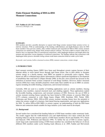
Finite Element Modeling of HSS-to-HSSMoment ConnectionsM.F. Fadden & J.P. McCormickUniversity of Michigan, USA.SUMMARY:HSS members provide a possible alternative to typical wide flange seismic moment frame systems in low- tomid-rise structures. With an understanding of the limiting width-thickness and depth-thickness ratios for HSSbeam members from previous studies, fully welded reinforced and unreinforced HSS-to-HSS seismic momentconnections are studied using Abaqus finite element analysis software. The beam width-to-column width ratio isfound to have an important effect on unreinforced connections, while diaphragm thickness and length affects themoment and equivalent viscous damping of reinforced connections. The findings indicate that connections withdiaphragms better preserve desirable strong column-weak beam connection behavior under cyclic loads.Keywords: steel systems, hollow structural sections (HSS), moment connections, seismic design1. INTRODUCTIONSteel moment resisting frames (MRF) have been used throughout seismic regions because of theirinherent ability to resist lateral forces through rigid frame action. Due to their ability to dissipateseismic energy in a ductile manner, steel MRFs are popular in seismically active regions. Theseframes are able to withstand large plastic deformations without significant degradation or developmentof instabilities that could lead to collapse (Roeder 2000). In the past, most research has focused on theutilization of moment frame systems composed of wide-flange members. However, hollow structuralsections (HSS) have many desirable properties which make them suitable for use in MRFs in seismicregions including favorable bending, compression, and torsional resistance.Currently, HSS are used in a number of building applications such as column members, bracingelements, truss members, exposed structural steel, and cladding supports. These applications exploitthe favorable bending, compression, and torsional resistance of HSS. However, the use of HSS inseismic moment resisting frames typically has been limited to HSS columns or concrete filled tube(CFT) columns connected to wide flange beams (Hajjar 2000, Kurobane 2002, Packer 2000,Nishiyama and Morino 2004). HSS-to-HSS seismic moment resisting frames have the potential toreduce the seismic weight of a structure, limit lateral bracing requirements, and open new applicationsfor HSS. To utilize HSS-to-HSS MRFs in seismic regions, an understanding of both the HSS beambehavior and connection details suitable for large inelastic cyclic loads must be developed.1.1. BackgroundSeveral studies have considered the bending behavior of HSS beam members under monotonic loads.The results suggest that the width-thickness (b/t) and depth-thickness (h/t) ratios control the localbuckling behavior and the moment capacity of HSS beam members (Korol and Hudoba 1972, Hasanand Hancock 1988, Wilkinson and Hancock 1998). To further the use of HSS in seismic regions,recent large-scale experimental testing of HSS beam members has considered the behavior of elevendifferent HSS members under cyclic bending loads (Brescia et al. 2009, Fadden and McCormick
2012a). Continuum finite element models have been developed and calibrated based on experimentaltesting utilizing measured material properties and capturing the local buckling behavior (Fadden andMcCormick 2012b). The cyclic bending study results reiterate the importance of b/t and h/t observedduring monotonic testing and provides a better understanding of the expected cyclic local bucklingbehavior.HSS have been used extensively in planar and multi-planar truss connections and HSS column-towide flange beam connections. Research on HSS trusses has shown that the ratio of the width of thebrace-to-the width of the chord governs the connection load carrying capacity (Davies et al. 1984,Koskimaki and Niemi 1990). As this ratio approaches 1.0, the failure mode changes abruptly becausethe webs of the chord stiffen the connection. While the use of HSS columns in the United States islimited, over 90% of steel buildings in Japan use HSS columns because of their ability to resist biaxialloads (Kurobane 2002). Since connections must behave in a rigid manner, unstiffened HSS columnsare not acceptable (Packer and Henderson 1997). In Japan, a number of studies addressed thisinadequacy by including internal and external connection diaphragms (Kamba and Tabuchi 1994) orby increasing the wall thickness (Kamba et al. 1994, Tanaka et al. 1996). Currently, design guides areavailable with recommendations for the design of HSS-to-HSS moment connections under static loads(Packer et al. 2009, AISC 2011) and seismic HSS-to-wide flange moment connections (Kurobane etal. 2004, AISC 2006).HSS-to-HSS moment connection studies are limited. Many early studies of the behavior of HSS-toHSS moment connections were performed on Vierenedeel truss connections. Unequal widthconnections are incapable of full moment transfer without reinforcement and are generally too flexibleto be considered rigid moment connections (Korol et al. 1977). Experimental testing has shown thatdoubler plates, stiffeners, and haunches can improve performance in monotocally loaded connections.One study has considered the use of hollow sections built from channel sections for a seismic momentconnection (Kumar and Rao 2006, Rao and Kumar 2006). This connection utilizes web openings toallow bolting and develops moment through shear lag in channel members welded to the column.A significant amount of work has been undertaken in the finite element modelling of wide flangebeam seismic moment connections. After the 1994 Northridge earthquake in the U.S., most studiesfocused on modelling the behavior of beam-to-column sub-assemblages (El-Tawil et al. 1998). Thesefinite element models more closely examined the state of stress in connections that experienced largeinelastic displacements and made recommendations for improved design details. Only a few modelshave been developed to consider HSS-to-HSS moment connection behavior. Korol and Mizra (1982)performed a study of 73 combinations of Vierendeel truss branch-to-chord connections consideringtheir ability to transfer moment. The findings show that increasing the width of the brace from 40% to80% of the chord width increases the moment capacity by 60%. More recent studies have consideredthe behavior of HSS connections, validating yield line theory approaches (Kosteski et al. 2002).1.2. ObjectiveThe finite element analysis study described in this paper addresses the ability of HSS-to-HSS momentconnections to form stable plastic hinges under large cyclic inelastic deformations. A parametric studyof 133 HSS beams allows for the determination of limiting depth-thickness (h/t) and width-thickness(b/t) ratios based on a finite element model calibrated to experimental results. Utilizing these limitingratios, reinforced and unreinforced HSS-to-HSS moment connections are developed. The effect of thebeam width-to-column width ratio (β) and beam depth are considered for the unreinforced connection.The use of internal and external diaphragms is then examined to better understand their ability todevelop the full moment capacity of the HSS beam member and achieve desirable strong columnweak beam behavior. The diaphragm thickness (td) and length (ld) are examined for their ability toimprove the performance of the connection under cyclic loads. This study provides insight intoconnection configurations that are likely suitable for HSS-to-HSS moment connections for seismicapplications.
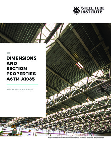
2. HSS BEAM BENDING BEHAVIOR2.1 Parametric study beam model setupA parametric study is undertaken to consider the effect of the b/t and h/t ratios on the local bucklingand cyclic hysteretic HSS bending behavior. The parametric study considers HSS beams with sizesbetween HSS 152.4x50.8x4.8 and HSS 508.0x304.8x15.9, providing a large set of sections and a widerange of widths, depths, and thicknesses. The wide range of sections allows for consideration of theeffect of local buckling on the degradation of the maximum moment capacity with respect to b/t andh/t. The results allow for a better understanding of the parameters that limit stable plastic hingeformation. The HSS members used in the parametric cyclic bending study are modelled using AbaqusFEA (DSS 2008). The beam finite element model (FEM) is calibrated to eleven experimentally testedsections (Fadden and McCormick 2012b) utilizing experimentally tested material properties andgeometric imperfections (Fig. 2.1).Figure 2.1 HSS finite element beam parametric study: (a) beam FEM, (b) cross-section dimensions, and (c)cyclic loading protocol.2.2 HSS cyclic bending behaviorThe cyclic hysteretic behavior is dependent on the b/t and h/t ratios. An increase in the b/t or h/t ratiocauses an increase in the amount and rate of degradation of the moment capacity of the HSS beam.Fig. 2.1 plots the percent degradation of the maximum moment capacity from the overall maximummoment to the moment capacity obtained during the 0.04 rad. cycle with respect to the b/t (Fig. 2.2a)and h/t (Fig. 2.2b) ratios.50%(a)% Degradation of Mmax at 0.04 rad.% Degradation of Mmax at 0.04 01020h/t30405060%Figure 2.2 Percent degradation of Mmax at 0.04 rad. with respect to (a) b/t and (b) h/tA linear regression analysis relates the b/t and h/t ratios to the percent degradation of the maximumcyclic moment at the 0.04 rad. cycle. The b/t ratio appears to have a larger effect on degradationcompared to the h/t ratio, but their slopes are similar with values of 0.011 and 0.010, respectively. Thelinear regression analysis results suggest that a larger value of h/t causes less degradation than a
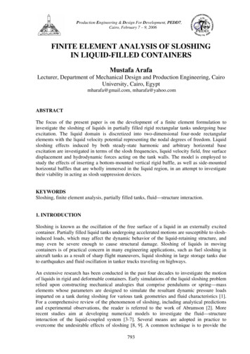
comparable b/t value. Based on this fact, the degradation of moment capacity is found to be moredependent on the b/t ratio. From this analysis, recommendations for the limiting b/t and h/t ratios forseismic design can be made. To ensure that a section will have adequate ductility under large cyclicrotations, beam sections should be chosen that have b/t and h/t ratios for which the moment capacityremains above 80% of the overall maximum moment when cycled to 0.04 rad. Utilizing the linearregression analysis, sections should have a minimum b/t ratio of 20 and a minimum h/t ratio of 36 toensure stable behavior.3. UNREINFORCED HSS-TO-HSS MOMENT CONNECTIONPrevious studies have considered the behavior of monotonically loaded unstiffened HSS-to-HSSexterior and interior connections (Korol et al. 1977). These connections are limited by several failuremodes including column face plastification, chord punching shear, fracture of the beam, chordsidewall yielding, and column shear. For connections with small beam width-to-column width ratios(β 0.85), the moment capacity can be determined by a yield line analysis. Connections with largebeam width-to-column width ratios (β 0.85) are limited by chord side wall failure. In order to betterunderstand the effect of β and the depth of the connection on the cyclic hysteretic behavior, a detailedfinite element model is developed and displaced cyclically to large rotations.3.1 Connection modelThe unreinforced connection model is composed of a HSS 355.6x355.6x15.9 column and ninedifferent HSS beam members. The beam members have depths of 254.0 mm, 304.8 mm, and 355.6mm and range in width from 101.6 mm to 304.8 mm. This allows for a wide range of β to beconsidered from 0.29 to 0.86. Fig. 3.1a shows an example finite element model. The column in themodel is 3962 mm long and pinned at each end, while the beam member is 2870 mm long. The beamis centered and fixed to the column member along all of the beam edges utilizing a tie constraint torepresent a fully welded connection. Material properties are the same as those used for the HSS beammodel (Fadden and McCormick 2012b). The finite element mesh is optimized utilizing S4R shellelements and does not implement initial imperfections. The loading protocol prescribes beam tipdisplacements following the same protocol as shown in Fig. 2.1c producing inter-story drifts up to0.06 rad.Figure 3.1 Unreinforced HSS-to-HSS exterior connection model (a) section geometry and (b) von Mises stressdistribution at 0.06 rad. rotation3.2 Unreinforced HSS-to-HSS moment connection behaviorAll connections show symmetric hysteretic behavior with increasing moment capacity throughout theloading protocol. The connection with the HSS 304.8x304.8x15.9 beam member reaches the highestmaximum moment of 270 kN-m at 0.06 rad. rotation, while the HSS 254.0x152.4x15.9 has the lowestmaximum moment of 835 kN-m at 0.06 rad. rotation. As previously noted, the beam width-to-columnwidth ratio (β) has an important effect on the behavior of the connection. Fig. 3.2 shows the measuredmoment normalized by the plastic moment capacity of the beam member versus the rotation of theconnections with HSS 304.8x152.4x15.9 (β 0.43), HSS 304.8x203.2x15.9 (β 0.57), and HSS
304.8x304.8x15.9 (β 0.86) beams. As β increases from 0.43 to 0.86, the normalized maximummoment increases from 0.26 to 0.36 with larger hysteretic loops. However, the plastic momentcapacity of the beam member is not fully utilized. The connection with the HSS 304.8x304.8x15.9beam member only reaches 36% of the beam moment capacity. Further, the plastic deformation of theconnection is concentrated at the column face, which is undesirable for seismic design (Fig. 3.1b).(a) HSS304.8x152.4x15.9(Beta 0.43)(b) HSS304.8x203.2x15.9(Beta .3-0.3-0.3-0.4-0.06 -0.04 -0.02-0.4-0.06 -0.04 -0.0200.02 0.04 0.06(c) HSS304.8x304.8x15.9(Beta 0.86)Rotation (rad.)00.02 0.04 0.06-0.4-0.06 -0.04 -0.02Rotation (rad.)00.02 0.04 0.06Rotation (rad.)Figure 3.2 Normalized moment-rotation hysteretic behavior for the unreinforced connection with (a) HSS304.8x152.4x15.9, (b) HSS 304.8x203.2x15.9, and (c) HSS 304.8x304.8x15.9 beamsThe effect of β on the normalized maximum moment for all modelled connections is shown in Fig.3.3a. All connections show improved maximum normalized moment with increasing β. Theconnection with the HSS 355.6x101.6x15.9 beam (β 0.29) reaches the lowest maximum normalizedmoment of 0.24, while the connection with the HSS 304.8x304.8x15.9 beam (β 0.86) reaches thehighest maximum normalized moment of 0.36. The effect of increasing β on the maximum momentcapacity is not linear. In connections with β smaller than 0.57, increasing the beam width does little toincrease the maximum normalized moment capacity. The connection with the HSS 304.8x101.6x15.9beam has a maximum normalized moment capacity of 0.25 and the connection with the HSS304.8x203.2x15.9 beam has a maximum normalized moment capacity of 0.28. This is an increase ofonly 0.03 for an increase in β from 0.29 to 0.57. When β increases above 0.7, the increase innormalized moment capacity becomes larger. The connection with the HSS 254.0x203.2x15.9 beamhas a normalized moment capacity of 0.29 at a β of 0.57 while the normalized moment capacityincreases to 0.34 when a beam with a β of 0.71 is used. None of the unreinforced sections utilize thefull moment capacity of the beam member even with β 0.85, showing that unreinforced connectionsunder cyclic loads are incapable of developing the beam plastic moment capacity and the use ofinternal and external stiffeners is necessary(a)0.35Max(M/Mp)beam0.350.3Depth 254.0 mm0.25Depth 304.8 mmDepth 355.6 mm0.2Equivalent Viscous Damping0.4(b)0.30.25Depth 254.0 mm0.2Depth 304.8 mmDepth 355.6 mm0.1500.250.5Beta0.75100.250.5Beta0.751Figure 3.3. Effect of the beam width-to-column width ratio (β) on the connection (a) maximum normalizedmoment and (b) equivalent viscous dampingEquivalent viscous damping provides a measure of the energy dissipation capacity normalized by theelastic strain energy times 4π. Consideration of the equivalent viscous damping is important tounderstand the ability of the connection to dissipate energy with increasing deformation cycles. Fig.3.3b plots the equivalent viscous damping at the first 0.06 rad. rotation cycle versus β. Increasing βcauses a linearly proportional increase in the equivalent viscous damping. The connection with the
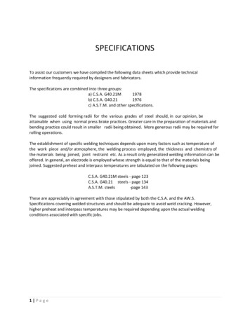
HSS 304.8x101.6x15.9 beam shows the lowest equivalent viscous damping at the 0.06 rad. cycle of0.17, while the connection with the HSS 304.8x304.8x15.9 beam shows the highest equivalent viscousdamping at the 0.06 rad. cycle of 0.30. Additionally for the same β, increasing the depth of the sectionleads to improved equivalent viscous damping. The HSS 254.0x152.4x15.9 beam connection has anequivalent viscous damping value of 0.18, while the HSS 355.6x152.4x15.9 beam connection has anequivalent viscous damping value of 0.22. This occurs because a deeper beam increases the yieldingarea of the column face. Increasing β is shown to be more effective than increasing the beam depth forequivalent viscous damping under cyclic loads for unreinforced HSS-to-HSS moment connections.4. REINFORCED HSS-TO-HSS MOMENT CONNECTIONTo improve the performance of HSS-to-HSS moment connections under cyclic loads, two rigidmoment connection details were created based on previously developed HSS columns-to-wide flangebeam connections (Kurobane et al. 2004). The connections (Fig. 4.1) utilize internal and externaldiaphragms to attempt to move forces generated by beam displacements away from the column faceand into the more rigid column sidewalls. This study considers diaphragms of different lengths (ld) andthicknesses (td) to better understand the effects of these parameters on the cyclic hysteric behavior.The internal diaphragm connection (Fig. 4.1a) utilizes plates that are continuous through the column.This connection requires cutting the column in two locations and reconnecting the column utilizingcomplete joint penetration (CJP) welds to the diaphragm plates. The external flange plate connection(Fig. 4.1b) utilizes plates that are cut to fit around the column face and sidewalls and is fillet weldedinto place. Both connections will utilize flare bevel groove welds between the beam and plates andfillet welds between the beam and column.(a)(b)Figure 4.1 Detail for the (a) internal diaphragm and (b) external diaphragm reinforced HSS-to-HSS exteriormoment connections4.1 Connection modelThe model used for the reinforced HSS-to-HSS moment connection is similar to that utilized for theunreinforced connection. Fig. 4.2a and Fig. 4.2b show the connection model for the internal andexternal diaphragm connections, respectively. All connections have a HSS 355.6x355.6x15.9 columnwith a HSS 304.8x203.2x15.9 beam providing a β of 0.57. The model utilizes shell elements for thebeams and columns and C3D8H hexahedral elements for the plates. The diaphragm dimensions areshown in Fig. 4.1 where thicknesses of 9.5, 12.7, 15.9, and 19.1 mm are considered and the lengths ofthe diaphragm considered are 152.4, 203.2, or 254.0 mm. The material properties for the beam andcolumns are the same as for the beam model and the diaphragms are assumed elastic perfectly plasticwith a yield stress of 250 MPa. Tie constraints are used between all adjoining edges and surfaces inthe model to connect the diaphragms and members. The mesh is optimized to improve calculationspeed and accuracy, but is subsequently less dense than the unreinforced connection model.
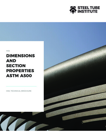
Figure 4.2 Reinforced HSS-to-HSS exterior connection model with the section geometry for the (a) internaldiaphragm and (b) external diaphragm connections and von Mises stress distribution at 0.06 rad. rotation for the(c) internal diaphragm and (d) external diaphragm connections.4.2 Internal diaphragm HSS-to-HSS moment connection behaviorAll internal diaphragm connections showed symmetric cyclic hysteretic behavior with improvedmoment capacity over the complimentary unreinforced connection. The connection with td of 19.1 mmand ld of 254.0 mm reached the highest maximum moment of 678 kN-m, while the connection with tdof 9.5 mm and ld of 152.4 mm achieved the lowest maximum moment of 399 kN-m. Overall, theconnection performs better than the unreinforced connection by moving yielding into the beam andcolumn sidewalls. The thickness of the internal diaphragms has an important effect on the behavior ofthe connection. Fig. 4.3 shows the normalized moment-rotation hysteresis for the 9.5 mm, 15.9 mm,and 19.1 mm thick diaphragms with a diaphragm length of 203.2 mm. With an increase in thickness,the normalized moment capacity increases from 0.72 for the 9.5 mm thick diaphragm to 1.21 for the19.1 mm thick diaphragm at 0.06 rad. rotation. Additionally, as the internal diaphragm plate becomesthicker, the hysteresis loops become fuller with reduced reduction in stiffness at large rotations.1.51.510.5M/(Mp)beamM/(Mp)beam1(b) HSS 304.8x203.2x15.9(tp 15.9 mm)0-0.50.50-0.5-100.02 0.04 0.06Rotation (rad.)0.50-0.5-1-1.5-0.06 -0.04 -0.02(c) HSS 304.8x203.2x15.9(tp 19.1 mm)1M/(Mp)beam1.5(a) HSS 304.8x203.2x15.9(tp 9.5 mm)-1-1.5-0.06 -0.04 -0.0200.02 0.04 0.06Rotation (rad.)-1.5-0.06 -0.04 -0.0200.02 0.04 0.06Rotation (rad.)Figure 4.3 Normalized moment-rotation hysteretic behavior for the internal diaphragm connection withdiaphragm thicknesses of (a) 9.5 mm, (b) 15.9 mm, and (c) 19.1 mm and a diaphragm length of 203.2 mmThe effect of the internal diaphragm thickness and length on the normalized maximum moment isshown in Fig. 4.4a. The connection with a 9.5 mm thick and 152.4 mm long diaphragm has the lowestnormalized moment capacity of 0.71, while the connection with a 19.1 mm thick and 254.0 mm longdiaphragm has the highest normalized moment capacity of 1.21. The length of the diaphragm is shownto have little effect on the maximum normalized moment capacity of the connection. However, anincrease in the thickness of the diaphragm shows a linearly proportional increase in the normalizedmoment capacity. Connections with a thickness greater than or equal to 15.9 mm thick and 203.2 mmlong have maximum normalized moment capacities greater than 1.0. In this case, the full plasticmoment capacity of the beam member is developed, which was not achievable with the unreinforcedconnection.
Fig. 4.4b plots the effect of changing diaphragm thickness and length on the equivalent viscousdamping capacity at a rotation of 0.06 rad. Changing thickness and length of the diaphragm has littleeffect on improving the equivalent viscous damping at 0.06 rad. The connection with a 15.9 mm thick,254.0 mm long diaphragm has the minimum equivalent viscous damping of 0.24, while the connectionwith a 9.53 mm thick, 254.0 mm long diaphragm has the maximum equivalent viscous damping of0.27. On average, the equivalent viscous damping is 0.26, whereas for the unreinforced connection theequivalent viscous damping is 0.23. More importantly, more yielding is occurring in the beam, columnsidewalls, and diaphragms rather than at the column face where plastic deformation is undesirable.0.3M/(Mp)beam1.21.110.90.8l plate 152.4 mm0.7l plate 203.2 mmEquivalent Viscous Damping1.30.250.20.150.1l plate 152.4 mm0.05l plate 203.2 mml plate 254.0 mml plate 254.0 mm0.6051015520tp (mm)101520tp (mm)Figure 4.4 Effect of the internal diaphragm thickness and length on the (a) normalized maximum moment and(b) equivalent viscous damping of the connection4.3 External diaphragm HSS-to-HSS moment connection behaviorExternal diaphragm connections show improved performance over the unreinforced connection, butnot the internal diaphragm connection. The connection with td of 19.1 mm and ld of 254.0 mm reachedthe highest maximum moment of 375 kN-m, while the connection with td of 9.5 mm and ld of 152.4mm achieved the lowest maximum moment of 251 kN-m. The connection moves some yielding intothe beam and column sidewalls. As with the internal diaphragm connections, the thickness of theexternal diaphragms has a significant effect on the moment capacity of the connection. Fig. 4.5 showsthe normalized moment-rotation hysteresis for the connections with a 9.5 mm, 15.9 mm, and 19.1 mmthick diaphragms and a diaphragm length of 203.2 mm. An increase in diaphragm thickness from 9.5mm to 19.1 mm leads to an increase in the normalized moment capacity from 0.47 to 0.65 at 0.06 rad.rotation. Overall, all connections show full, symmetric hysteretic loops indicating stable behavior.(a) HSS 304.8x203.2x15.9(tp 9.5 mm)0.8(b) HSS 304.8x203.2x15.9(tp 15.9 6-0.6-0.8-0.06 -0.04 -0.02-0.8-0.06 -0.04 -0.0200.02 0.04 0.06Rotation (rad.)(c) HSS 304.8x203.2x15.9(tp 19.1 mm)00.02 0.04 0.06Rotation (rad.)-0.8-0.06 -0.04 -0.0200.02 0.04 0.06Rotation (rad.)Figure 4.5 Normalized moment-rotation hysteretic behavior for the external diaphragm connection withthicknesses of (a) 9.5 mm, (b) 15.9 mm, and (c) 19.1 mm and a diaphragm length of 203.2 mmThe effect of the external diaphragm thickness and length on the normalized maximum moment isshown in Fig. 4.6a. The connection with a 9.5 mm thick and 152.4 mm long diaphragm has the lowestnormalized moment capacity of 0.45, while the connection with a 19.1 mm thick and 254.0 mm longdiaphragm has the highest normalized moment capacity of 0.67. Unlike the internal diaphragmconnections, utilizing the external diaphragm shows improved moment capacity with increasing
diaphragm length. Increasing the diaphragm length from 152.4 mm to 254.0 mm increases thenormalized moment capacity on average by 0.05 for all external diaphragm connections. Additionally,an increase in the thickness of the diaphragm shows a linearly proportional increase in the normalizedmoment capacity. The external diaphragm connection is unable to produce a moment capacity greaterthan the beam plastic moment capacity. The connection still shows considerable plastification of thecolumn face (Fig. 4.2d). Fig. 4.6b shows that changes in length and thickness of the diaphragm platedo not cause large changes in the equivalent viscous damping capacity of the connection at 0.6 rad.rotation. On average, the equivalent viscous damping is 0.31, which is larger than the internaldiaphragm connection and comparable to the unreinforced connection. In general, external diaphragmconnections improve the behavior compared to the unreinforced connection, but may not be adequateto provide strong column-weak beam seismic moment frame behavior.0.7M/(Mp )beam0.650.60.550.5l plate 152.4 mm0.45l plate 203.2 mmEquivalent Viscous Damping0.40.350.30.250.20.15l plate 152.4 mm0.1l plate 203.2 mm0.05l plate 254.0 mm0.4l plate 254.0 mm051015tp (mm)205101520tp (mm)Figure 4.6 Effect of the external diaphragm thickness and length on the (a) normalized maximum moment and(b) equivalent viscous damping of the connection5. CONCLUSIONSThe results of a finite element study considering the cyclic behavior of unreinforced and reinforcedHSS-to-HSS moment connections is presented. The study utilizes findings from a previouslydeveloped HSS beam model. This model allows for the determination of limiting b/t and h/t ratios forthe HSS beam member to ensure stable plastic hinging in the beam under cyclic loads. The behavior ofunreinforced HSS-to-HSS moment connections is studied under cyclic loads to develop a relationshipbetween the beam width-to-column width ratio and the load carrying capacity and equivalent viscousdamping behavior. Reinforced HSS-to-HSS moment connections are then studied utilizing internaland external diaphragms to improve upon the load carrying capacity of the connection under cyclicloads. The effect of varying the diaphragm plate length and thickness on the cyclic moment capacityand equivalent viscous damping of the connection also is considered.Overall, unreinforced and external diaphragm HSS-to-HSS moment connections are not adequate indeveloping the full moment capacity of the beam member. HSS-to-HSS connections utilizing internaldiaphragms with diaphragm thickness and length greater than or equal to 15.9 mm and 152.4 mm,respectively, are capable of developing the full moment capacity of the beam. Internal diaphragmconnection capacity is governed by diaphragm thickness, while external diaphragm connectioncapacity is governed by both diaphragm length and thickness. Comparing the state of stress in themember at 0.06 rad. rotation, it is clear that reinforcement helps move yielding away from the columnface and into the beam and column sidewalls allowing for more desirable yielding mechanisms.Additionally, both internal and external diaphragms help improve the equivalent viscous dampingcapacity of the connection, but diaphragm length and thickness have little effect on this parameter.These findings further suggest the suitability of HSS-to-HSS moment connections in low-rise HSS-toHSS seismic moment frame systemsAKCNOWLEDGEMENTThis work is supported by the BRIGE Program of the National Science Foundation under Grant No. EEC0926858 and the American Institute of Steel Construction through the Milek Fellowship. The views expressed
herein are solely those of the authors and do not represent the views of the supporting agencies.REFERENCESAISC. (2006). Seismic Sesign Manual. American Institute of Steel Construction, Chicago, IL.AISC. (2011). Manual of Steel Construction 14th Ed., American Institute of Steel Construction, Chicago, IL.Brescia, M., Landolfo, R., Mammana, O., Iannone, F., Piluso, V., and Rizzano, G. (2009). Preliminary results ofan experimental program on the cyclic response and rotation capacity of steel members. STESSA 2009. 971976.Davies, G., Packer, J.A., & Coutie, M.G. (1984). The behaviour of full width RHS cross joints. ISTS 1984. 411418.DSS (2008). Abaqus FEA Version 6.8-1 Documentation Collection. Dassault Systemes Simulia Corp.Providence, RI.El-Tawil, S., Mikesell, T., Vidarsson, E., and Kunnath, S.K. (1998). S
HSS have been used extensively in planar and multi-planar truss connections and HSS column-to-wide flange beam connections. Research on HSS trusses has shown that the ratio of the width of the brace-to-the width of the chord governs the connection load carrying capacity (Davies et al. 1984, Koskimaki and Niemi 1990).