Transcription
Top Things To Know AboutHSS ConnectionsSEAoPAPhiladelphia, PAWednesday, December 2, 2015Brad Fletcher, S.E.
Atlas Tube – Market Leader Largest size range in North America 1”–16” square, up to 5/8” wall 1.25” – 20” round, up to 5/8” wall Now offering Jumbo HSS Shortest rolling cycle in the industry 2 – 3 weeks for common sizes Able to roll custom lengths to minimize cost, waste, columnsplices Rolled lengths up to 135 ft. for rounds, up to 85 ft. for sq. & rect. Four production facilities in North America Metallurgists and Structural Engineer on staff to assist withtechnical and product questions Products stocked by service centers across North America
Jumbo HSSThrough a partnership with NSMP &Mitsui, Atlas is now offering large HSS 10” & 12” sq. x .750”14” & 16” sq. x .750”, .875”18” & 20” sq. x .5”, .625”, .750”, .875”22” sq. x .750”20” x 12” x .750”24” x 12” x .5”, .625”, .750”Material stocked and readily availableLarge quantities can be mill orderedAvailable as A500 or CSA G40Also available in new ASTM A1085
Jumbo HSS Jumbo HSS listed onAISC website asavailable throughAtlas November 2011Modern SteelConstruction article Column DesignTables in AISC formatavailable to downloadfor free from AISCwebsite www.atlastube.com/jumbo-hss www.aisc.org/hss
Why 0.93? Per AISC 360-10, Section B4.2:“The design wall thickness, t, shall be used in calculations involving the wall thickness ofhollow structural sections (HSS). The design wall thickness, t, shall be taken equal to0.93 times the nominal wall thickness for electric-resistance-welded (ERW) HSS andequal to the nominal thickness for submerged-arc-welded (SAW) HSS.” ERW HSS – produced to ASTM A500 and A53 SAW HSS- typically sizes larger than permitted in the A500 (ASTM A1065) Per CISC Handbook of Steel Construction “ Design Wall Thickness is taken as 0.90 times the nominal thickness.” Tolerances ASTM A500 – Wall thickness tolerance: /- 10% ASTM A53 – Wall thickness tolerance: -12.5%
Why 0.93?AISC 360-10, Chp K, Section 1.1:“t design wall thickness of HSS, in. (mm)”
Welded Plate vs. Slotted Through Plate For rect/sq HSS slottedthrough plate has twice thecapacity compared towelded plate Slotted plate is moreexpensive to fabricate Is double the capacityneeded and warrant theadditional cost? Can this be applied toround HSS?
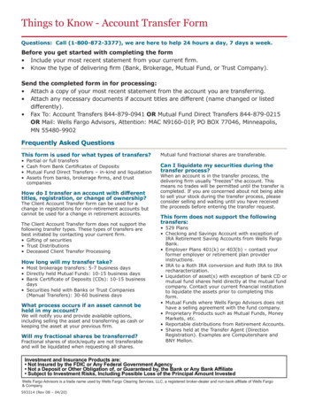
Slotted HSS Gusset Plate Connections Check Limit States associated with HSS HSS Tensile Yielding (Gross Area) HSS Tensile Rupture (Net Section) – Need toaccount for effective area (due to slot extendingfurther than plate) and the effect of shear lag. Base metal shear in HSS & gusset plate Weld metal shear Typical gusset plate limit states due to bolting Cannot develop yield strength of bracingmember due to shear lag Per AISC 360 Table D3.1 ( Shear Lag Factor U) Except Case 5 – Round HSS with weld length l 1.3D Length of weld l should be H or D(distance between welds) This is implied with U factors in Table D3.1 (Cases 5& 6)
Slotted HSS Gusset Plate Connections
Cast Connections Can be a unique, highly aestheticsolution to the connection “problem” Typically custom made, project specific,expensive Usually thought of when dealing withnodes
Cast Connections – Cast Connex Can also be used for “everyday”connections such as diagonal bracing “Off the shelf” castings are becomingmore popular Good, cost competitive solution for SCBFsin high seismic zones Energy-dissipative bracing system isdesigned to produce hinging at mid-lengthof the brace and in the gusset plates ateach end, with the cast connectorremaining elastic Extensively tested, ICC-ES in California
Cast Connections – Cast ConnexOther Options Tapered Connection Pinned Connection
Shear Connections All shear connections used to connect WF beams to WFcolumns can be used to connection WF beams to HSScolumns. Single & Double AnglesStiffened & Unstiffened SeatsSingle shear plates (shear tabs)Tee connectionsOnly unique HSS shear connection is through-plate
Connections – Line/Concentrated LoadsPlate-to-HSS welded More flexible than platewelded to W-shapeLimit States HSS wall plastification Local plate yielding HSS Shear yielding(punching) HSS sidewall strengthUse thicker HSS wallConnection reinforcing
Moment Connections - Seismic Moment connections used in SMF and IMF need to be “prequalified” or tested in accordance with AISC 341-10, Chapter K.AISC 358-10 Prequalified Connections for Special andIntermediate Steel Moment Frames for Seismic Applications listsall those connections that have met the criteria of 341-10, Chp K.Only one moment connection listed directly pertains to HSS ConXtech ConXL connection
Moment Connections - SeismicHow do you use HSS in SFRS? Avoid using AISC 341-10 Seismic Provisions Seismic Performance Category A Seismic Performance Category B or C, with R 3 Use OMF Prequalify (Develop & Test) a moment connection Current research at Univ. of Michigan – HSS-to-HSS momentconnections
Moment Connections — TypesContinuous Roof Beam Suitable for single-story structuresOnly top of beam is considered bracedAdditional stiffening or bracing required
Moment Connections — TypesContinuous Beam at Column Splice HSS column is interrupted at continuous beamFor lightly loaded columns, stiffener plates can be used to transfer axial forcesHeavy loads may require a split HSS on either side of the beam web.Beam flange should be wider than HSS. Rectangular HSS may be required tofit base plate on beam.Moment transfer to HSS column is dependent on strength of bolts, beamflange thickness, and base and cap plate thickness.
Moment Connections — TypesThrough-PlateDiaphragm Good for larger momenttransfer through joint More difficult and costly tofabricate and erect Can be placed at column splice Column moment transfer islimited by fillet weld of the HSSto through plate. PJP or CJPwelds can be used to increaseconnection strength. Good for two-way momentframe system.
Moment Connections — TypesDiaphragm Plate An alternative to thethrough plate connection. Diaphragm plates maybe field welded or shopwelded. When used with beamon one side, additionallyneed to check the weldtransferring shear to theHSS wall.
Moment Connections — TypesDiaphragm & through plate connectionscan be adapted to better facilitate erection.Beam stubs can be shop attached tocolumn to allow for field bolting or welding.
Moment Connections — TypesEnd Plate Utilizes end plate or angles Need to consider/coordinateprojection of plates beyondHSS Flange width of beamshould be as large or largerthan the HSS width tomaximize efficiency Buckling strength of HSSside wall needs to bechecked
Moment Connections — TypesDirectly Welded May develop full flexuralcapacity of HSS Cannot develop full flexuralcapacity of W shape To achieve max efficiency,HSS wall should be thickand beam flange widthshould match HSS flatdimension (B-3t)
Truss ConnectionsConnections at the panelpoints of a planar trussTrusses are typically analyzedwith branch members “pinned”Truss connections aredesigned astension/compressionconnections
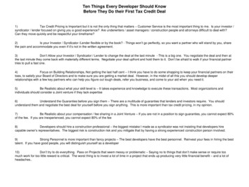
Truss Connections - Nomenclature
Truss Connections - Overlap JointsPartial Overlap100 % Overlap
Truss Connections - AnalysisThree options for analysis of planar welded HSS trusses: Pin Jointed Analysis – All members pinned Pin Jointed Web Members, Continuous Chord Members Extremely stiff members can be used to model the nodal eccentricity, e Rigid Frame Analysis – Everything fixed
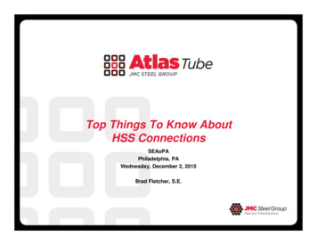
Truss Connections - Joint TypesT or Y-JointGap K-Joint(includes N)X-Joint or CrossOverlap K-Joint
Truss Connections - Joint Types Classification of joints is based on method of force transfer in theconnection and not the physical appearance of the connection When branch members transmit part of their forces as oneclassification and part as another, then the adequacy of eachbranch is determined by linear interaction in proportion to howeach portion is transferred.K ConnectionCross (X) Connection
Truss Connections - Fabrication Costs Minimum weight does not equal minimum cost Keep the number of different sizes small Try to minimize number of connections Warren trussesUnderstand effects of joint configuration andconnection design criteria before analyzing trussand selecting member sizes!
Truss Fabrication Costs - Effect of Joint TypeLowestCostRHS chord — gap jointsLowest JointStrength &StiffnessRHS chord — 100% overlap jointsCHS chord — gap jointsRHS chord — partial overlap jointsCHS chord — 100% overlap jointsHighestCostCHS chord — partial overlap jointsHighest JointStrength &StiffnessMatched sizes will have higher fabrication cost versus unmatched
WeldingGenerally for economicsspecify a fillet weld for tubularjointsProper joint design shouldallow you to avoid completejoint penetration weldsFor trusses subject to fatiguedesign, weld sequence isimportant. Overlapconnections have beensuggested for fatigue loading.
Truss Connections – Round Branch, Sq Chord Not covered by AISC 360-10, Chapter K However, Chp K Commentary states you can use“other verified design guidance ” Research by Packer, J.A., Mashiri, F.R., Zhao, X.L. andWillibald, S. (“Static and Fatigue Design of CHS-toRHS Welded Connections using a Branch ConversionMethod”, Journal of Constructional Steel Research,Vol. 63, No.1, 2007, pp. 82-95.) For calculation purposes you “convert” the roundsections to square sections and then use the Chp Kequations. Branches of diameter D are replaced by members ofwidth B (π/4)*D and the same wall thickness is used.
HSS Connections - ResourcesAISC 360 — Chapter K 2005 & 2010AISC Design Guide #24CISC Design Guide 1997CIDECT Design Guides Available for free on AISC websiteSteel Tube Institute HSS CONNEX OnlineConnection Spreadsheets
The New HSS SpecificationASTM A1085
New ASTM A1085 Specification New specification was developed by the HSSindustry in conjunction with AISC (American Instituteof Steel Construction) Was developed to address performance issuesrelated to HSS used in seismic and bridgeapplications Will make HSS more economical and efficient andraise the level of performance for construction,especially for bridge and seismic design.
New ASTM A1085 Specification - Why? Seismic Applications About half of the buildings designed andconstructed in North America have some levelof seismic design requirements.In North America, HSS are commonly used asbracing members in braced frames in seismiczones.Researchers are looking for more ways to usethe advantages of HSS in building designDynamic Applications Vehicle and pedestrian bridges are governedby AASHTO.ASTM A709 has Charpy requirementsHSS becoming more popular for bridges in USThe AWS (American Welding Society) hasrecently formed a Tubular Task Group todevelop a document for tubular bridgeconnections that is suitable for use byAASHTO. Provisions are to be tailored foruse in welded tubular bridges.
ASTM A1085Minimum yield stress of 50 ksi All sizes and shapes will have same min design valueMaximum yield stress of 70 kis Actual yield stress cannot exceed 70 ksi Will reduce capacity design requirements for seismic Ry 1.25 per AISC 341 (Seismic Design Provisions)YieldStressTensileStressASTM A500Grade BGrade CRound42 ksi min46 ksi minSq/Rect46ksi min50 ksi minRound58 ksi min62 ksi minSq/Rect58 ksi min62 ksi minASTM A1085AllShapes50 ksi min70 ksi max65 ksi min
ASTM A1085Standard requirement for Charpy V-Notch Toughness Minimum of 25 ft-lb @ 40 degree F Zone 2, Fracture Critical Elements per ASTM A709/AASHTOM270CVNSupplementalRequirementsAtlas Tube/JMCASTM A500ASTM A1085N/A25 ft-lbs@40FN/AOptional heattreatingOptional varyingCVN
ASTM A1085Tighter Material Tolerances Full nominal wall thickness can be used for design Will not need to apply 0.93 reduction per AISC for memberselection and connection design More available area and higher yield leads to more efficientand economical designsASTM A500ASTM A1085Wall thickness-10%-5%Mass toleranceN/A-3.5%
HSS Spec Comparison ChartYieldStrengthksi, minTensileStrengthksi, minElongation%, rRadiusA500 Grade BRnd 42Sq/Rec 46No Max58No Max23NA-10% 10%NA3t MaxA500 Grade CRnd 46Sq/Rec 50No Max62No Max21NA-10% 10%NA3t MaxCSA G40 50W50No Max65 – 9022Cat 1: 20 ft-lbo@ 32 FCat 2: 20 ft-lbo@0 F-5% 10%-3.5% 10% 6x6x.5Varies (2t-4t) 6x6x.53t maxA53 Grade B35No Max60-NA-12.5%-10%NAAPI 5L PSL X52N52No Max67-20 ft-lb @ 32F-10%1/4” t 5/8”-3.5%regular plainendNAEN10210 S355J2H51.5 fort 5/8”No Max682220 ft-lb @ 0F-10%-6%3t Max-10% t 1/4’’ 0.02’’ t 1/4’’ &D 16’’-6%t 1/4” 1.6t2.4t¼” t 3/8” 2t3tt 3/8” 2.4t3.6t-5% 10%-3.5% 10%t .4”1.6t - 3.0tt .4”1.8t - 3.0tEN10219 S355J2H51.5 fort 5/8”No Maxooo682020 ft-lb @ 0F2125 ft-lb @ 40FoASTM A108550 - 7065
ASTM A1085For additional information: www.atlastube.com/astma1085 www.aisc.org/hss www.aisc.org/a1085 onastm-a1085
Questions?THANK YOU!www.atlastube.com
Continuous Beam at Column Splice HSS column is interrupted at continuous beam For lightly loaded columns, stiffener plates can be used to transfer axial forces Heavy loads may require a split HSS on either side of the beam web. Beam flange should be wider than HSS. Rectangular HSS ma