Transcription
D4.4 Comparative study ofthe dynamic response ofHSS and CSS floor systemsReport to:RFCS, as deliverable from the researchproject:Stronger Steels in the Built ebruary 2021
D4.4 Comparative study of the dynamic response of HSS and CSS floorsSCI (the Steel Construction Institute) has been a trusted, independent source ofinformation and engineering expertise globally for over 30 years, and is one of theleading, independent providers of technical expertise and disseminator of best practiceto the steel construction sector.We support everyone involved in steel construction; from manufacturers, consulting anddesign engineers, architects, product developers to industry groups.Version0102IssueDatePurpose01 April 2020 Draft01Feb 2021 FinalAuthor Reviewer ApprovedAQCAQC CTH/NRB CTH/NRBAlthough all care has been taken to ensure that all the information contained herein isaccurate, The Steel Construction Institute assumes no responsibility for any errors ormisinterpretations or any loss or damage arising therefrom.P:\OSM\OSM640 STROBE\Deliverables\Ready for upload\pdf\STROBE D4-4 Comparative study of dynamic response of HSS floors.docxii
D4.4 Comparative study of the dynamic response of HSS and CSS floorsContentsPage No1INTRODUCTION42FLOOR VIBRATION ANALYSIS: FINITE ELEMENT ANALYSIS APPROACH 62.1 FE Implementation Suggestions62.2 Modal outputs82.3 Steady-state response82.4 Transient response102.5 Response factor122.6 Acceptance criteria123DEFINITION OF STUDY CASES3.1 Floor loading3.2 Deck type3.3 Beams3.4 Bay geometry3.5 Number of bays3.6 Damping ratios3.7 Floor excitation14141515161717174Equivalent HSS, hybrid and CSS floor systems185SENSITIVITY OF RESPONSE FACTORS TO KEY DESIGN PARAMETERS205.1 Composite floors205.2 Non-composite floors305.3 Non-composite floors using hybrid beams305.4 Summary306COMPARATIVE EVALUATION OF DYNAMIC RESPONSE6.1 Composite floors6.2 Non-composite floors6.3 Non-composite floors using hybrid beams6.4 x ANon-composite floorsA.1 Sensitivity studyA.2 Comparative study424251Appendix BNon-composite floor using hybrid beamsB.1 Sensitivity studyB.2 Comparative study585863P:\OSM\OSM640 STROBE\Deliverables\Ready for upload\pdf\STROBE D4-4 Comparative study of dynamic response of HSS floors.docxiii
D4.4 Comparative study of the dynamic response of HSS and CSS floors1INTRODUCTIONSteel framed structures are commonly criticised for tending to have problems with thevibration of floors. In response to this criticism, the steel industry has sought to developan objective measurement system for assessing the susceptibility of a floor to adversecomment from users. This work has been conducted as part of the HIVOSS 1 RFCSproject, then updated and published as part of SCI publication P354 Design of Floors forVibration: A New Approach2. Structures designed to P354 have not been reported tohave vibration problems, so the assessment method can be considered a success.While conventional strength steel (CSS) floors are perceived to have issues withvibration the perception is even more acute when high strength steel (HSS) or beamswith hybrid sections are considered. While the lower weight for a given span iseconomically favourable, HSS and hybrid floors are intuitively unfavourable for vibrationperformance.Although it may be true that floors utilising HSS may be more susceptible to vibrationthan equivalent solutions in CSS, previous experience and knowledge have shown thatthe response as a whole is not particularly sensitive to the selection of beams. It couldtherefore be expected that the difference between an equivalent HSS and CSS floor iseither small or negligible.There are two key issues that will be addressed in this project: (1) lack of availability ofanalysis tools and (2) a perception that the vibration response of HSS floors is worsethan that of CSS floors.To address issue (1), a floor vibration analysis (FVA) tool based on finite elementmethods has been developed in Task 4.2 for calculating the dynamic performance of agiven floor design in terms of a response factor (the ratio of the predicted accelerationdivided by a baseline value). This tool is reported in D4.2 and D4.3. The user can inputinformation about the floor grid, loading etc. via a simple interface. The beam sectionsizes can be either user-defined or the FVA tool can determine primary and secondarybeam sizes with lowest weight using the optimisation tool developed in Task 4.1 of WP4.The FVA tool then calculates the critical response factor for the floor system byperforming an eigenvalue analysis followed by a footfall analysis. The mode shapes,frequencies and modal masses for the floor are obtained and used to calculate theacceleration of the floor in response to footfall. In accordance with the assessmentmethod in SCI P354, the steady state response factor is determined from the weightedroot mean square (rms) acceleration and the transient state response factor from theweighted peak acceleration. The critical response factors are compared againstregulatory limits in ISO 101373.In this task, the calculation engine (Reported in D4.2) of the FVA was used in acomparative study to address issue (2) mentioned above. The dynamic response of morethan 10,000 different floor designs were analysed for HSS and hybrid floor systems andin this report the results are compared against functionally equivalent designs in CSS.The sensitivity of response factors to various key parameters (fundamental frequency,bay arrangement, length, loading and slab thickness etc.) are compared for CSS, HSSand hybrid floor systems.P:\OSM\OSM640 STROBE\Deliverables\Ready for upload\pdf\STROBE D4-4 Comparative study of dynamic response of HSS floors.docx4
D4.4 Comparative study of the dynamic response of HSS and CSS floorsThis report firstly presents a brief introduction to the floor vibration analysis methods inaccordance with design guide SCI P3542 which is used by the FVA tool. This is followedby definition of the scope of key design parameters and then sensitivity and comparativestudies to investigate the dynamic response of HSS, hybrid and CSS (S355) floorsystems.The sensitivity study reveals that the dynamic response of different floor systems (interms of steel strength) demonstrate similar sensitivity to various key parametersincluded in the study. The results can be used to optimise the design of floor systemswith respect to dynamic response.The comparative study shows that HSS and hybrid floors are not necessarily alwaysmore susceptible to vibration than equivalent CSS solutions, and the difference betweenthem is relatively small for most of the cases. It was shown that the dynamic responseas a whole is not particularly sensitive to the stiffness and mass of the beams (hence tothe steel strength), it is more sensitive to the slab depth and the span of the primary andsecondary beams. No special consideration is needed for specifying higher strength orhybrid steel beams with respect to vibration response.P:\OSM\OSM640 STROBE\Deliverables\Ready for upload\pdf\STROBE D4-4 Comparative study of dynamic response of HSS floors.docx5
D4.4 Comparative study of the dynamic response of HSS and CSS floors2FLOOR VIBRATION ANALYSIS: FINITEELEMENT ANALYSIS APPROACHThe dynamic performance can be established through finite element modelling of thefloor system. The finite element method is an approximation: it takes a continuousstructure and breaks each part of the structure into a number of smaller parts, also knownas a finite number of elements. The relationships between these elements are thendetermined using methods for multi-degree-of-freedom discrete systems. The accuracyof the solution is primarily dependant on the number of elements that the system isbroken into, but with increased accuracy comes increased complexity and hence highercomputation times.The finite element method for floor vibration analysis presented in this section is used bythe FVA tool, which is used in the current comparative study.2.1FE Implementation SuggestionsThe following are some recommendations for modelling techniques and assumptions forthe FE model. Any improvements will lead to a greater accuracy in predicting thevibration response of floors: The dynamic modulus of elasticity of concrete should be taken, for normal concrete,as equal to Ec 38 kN/mm2. Shell elements are recommended to represent the floor slab. All connections should be assumed to be rigid (in vibration the strains are not largeenough to overcome friction and so nominally pinned joints may be treated as fixed). Column sections should be provided and pinned at their theoretical inflexion points(located at mid-height between floors for multi-storey construction). Continuous cladding provided around façades may be assumed to provide full verticalrestraint for perimeter beams. The edge of buildings should normally modelled aspinned. The interface at cores should be modelled as fully restrained. The mass of the floor should be equivalent to the self-weight and other permanentloads, plus a proportion of the imposed loads which might be reasonably expected tobe permanent.One of the most difficult properties to estimate is the level of damping that is present inthe floor, due to the fact that it is strongly influenced by finishes and non-structuralcomponents. Recommended values of damping are given in Table 2.1.Table 2.1Critical damping ratios for various floor types Floor finishes0.5%Fully welded steel structures, e.g. staircases1.1%Completely bare floors or floors where only a small amount of furnishingsare present.3.0%Fully fitted out and furnished floors in normal use.4.5%A floor where the designer is confident that partitions will beappropriately located to interrupt the relevant mode(s) of vibration (i.e.the partition lines are perpendicular to the main vibrating elements of thecritical mode shape).P:\OSM\OSM640 STROBE\Deliverables\Ready for upload\pdf\STROBE D4-4 Comparative study of dynamic response of HSS floors.docx6
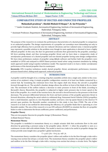
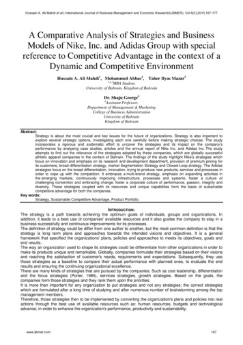
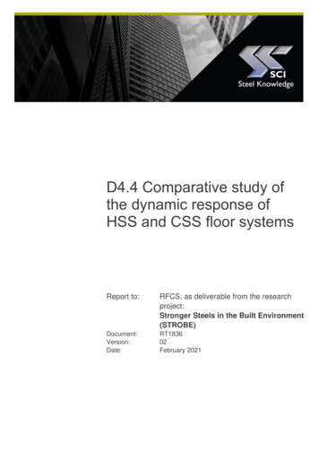
D4.4 Comparative study of the dynamic response of HSS and CSS floorsAnother important issue for properly modelling the floor structure is the offset of thebeams from the slab to achieve composite action. SCI P354 section 6.1.2 provides twoalternative ways to model the beams, with or without offset. The first option, with offset,was chosen for the modelling of the floor system for the FVA tool.Echczel,aEchcEczel,aIyE cxIy(a)Figure 2.1Slab and beam modelling for finite element analysisFigure 2.1 shows the modelling option adopted. The model uses orthotropic shellelements of a depthhc with elasticE c modulus EEccxtransverse to the ribs of the slab and Ecxhcparallel to the spanzoftheribs,with:Icel,a𝐸𝑐𝑥 𝐸𝑐12𝐼𝑐,𝑥(b)ℎ𝑐 3(2.1)where:𝐼𝑐,𝑥is the second moment of area of the profiled slab per metre width in thespanning directionℎ𝑐is the depth of concrete above the profile𝐸𝑐is the dynamic elastic modulus of concrete 𝐸𝑐 38 kN/mm2 as definedpreviouslyThis option also uses a beam element with the same properties and the same offset asthe design. As the slab is modelled using uniform thickness of hc, the offset, hs, is:ℎ𝑠 ℎ ℎ𝑎 𝑧𝑒𝑙,𝑎 ℎ𝑐2(2.2)where:ℎis the depth of the slab (including ribs)ℎ𝑎is the depth of the steel beam𝑧𝑒𝑙,𝑎is the height of the neutral axis of the steel beamℎ𝑐is the depth of concrete above the profileGiven that a doubly symmetric beam is used, the offset of the beam would simply be halfof the total depth of concrete slab and beam.There are no specific rules for the size of the element (mesh). In general, if the numberof elements can be doubled without significantly changing the frequencies then there aresufficient elements. The size of element was determined to be 0.8 m for the FE modelused in the FVA tool. Figure 2.2 shows the FE models created using ANSYS (as usedfor the SCI vibration consultancy service) and Calculix (open-source FE package usedin this work).P:\OSM\OSM640 STROBE\Deliverables\Ready for upload\pdf\STROBE D4-4 Comparative study of dynamic response of HSS floors.docx7
D4.4 Comparative study of the dynamic response of HSS and CSS floors(a) ANSYS modelFigure 2.22.2(b) CalculiX model (FVA tool)Example of a meshed 2x4 floor finite element modelModal outputsThe general purpose proprietary finite element software ANSYS is used for modellingthe floors in the SCI floor vibration analysis service. For the FVA tool developed inSTROBE, the open-source and free FE software CalculiX is used instead. Modalanalysis is performed to determine the modal properties, such as frequencies, modalmasses and mode shape amplitudes.The mode shape amplitudes can be ‘unity normalised’ (against peak value of theamplitude) or ‘mass normalised’ (against the modal mass of each mode) in ANSYS.CalculiX only produces mass normalised mode shape amplitudes. It will be shown laterthat this does not affect the calculation of the floor response.2.3Steady-state responseFor the steady-state case, the first four harmonic components from a person engaged inwalking activity are considered to represent the forcing function applied to the floor (otherspecialist forcing functions will be included and used in this task). The appropriate designvalues of the Fourier coefficients for these harmonic components are obtained fromTable 2.2:P:\OSM\OSM640 STROBE\Deliverables\Ready for upload\pdf\STROBE D4-4 Comparative study of dynamic response of HSS floors.docx8
D4.4 Comparative study of the dynamic response of HSS and CSS floorsTable 2.2Design Fourier coefficients for walking activitiesHarmonic Excitation frequency range Design value of coefficient Phase anglehhfp (Hz) h h11.8 to 2.20.436(hfp – 0.95)023.6 to 4.40.006(hfp 12.3)- /235.4 to 6.60.007(hfp 5.2) 47.2 to 8.80.007(hfp 2.0) /2Square root sum of squares (SRSS) is the method used to determine the maximum rmsacceleration response 𝑎𝑤,𝑟𝑚𝑠,𝑒,𝑟 at a point on the floor area subject to an excitation forceFh (often applied at the same point), and it gives the same results as a full time history.𝑎𝑤,𝑟𝑚𝑠,𝑒,𝑟 1 2𝐻𝑁 ( (𝜇𝑒,𝑛 𝜇𝑟,𝑛ℎ 1𝑛 12𝐹ℎ𝐷 𝑊 ))𝑀𝑛 𝑛,ℎ ℎ(2.3)where:𝜇𝑒,𝑛is the mode shape amplitude, from the unity or mass normalised FE output,at the point on the floor where the excitation force Fh is applied𝜇𝑟,𝑛is the mode shape amplitude, from the unity or mass normalised FE output,at the point where the response is to be calculated𝐹ℎis the excitation force for the hth harmonic for the Fourier coefficients forwalking, where 𝐹ℎ 𝛼ℎ 𝑄 (N)𝑀𝑛is the modal mass of mode n (kg), when the mode shape amplitude is massnormalised Mn 1 kg𝐷𝑛,ℎis the dynamic magnification factor for acceleration𝑊ℎis the appropriate code-defined weighting factor for human perceptionThe dynamic magnification factor for acceleration, which is the ratio of the peakamplitude to the static amplitude, is given by the following:𝐷𝑛,ℎ 𝛽2(2.4) (1 𝛽𝑛2 )2 (2𝜁𝛽𝑛 )2where:ℎis the number of the hth harmonic𝛽𝑛is the frequency ratio (taken as 𝑓𝑝 /𝑓𝑛 )𝜁is the damping ratio𝑓𝑝is the frequency corresponding to the first harmonic of the activity (fp 2.2 Hzis used in the current analysis)P:\OSM\OSM640 STROBE\Deliverables\Ready for upload\pdf\STROBE D4-4 Comparative study of dynamic response of HSS floors.docx9
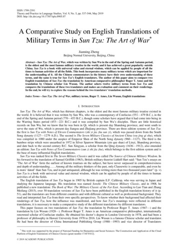
D4.4 Comparative study of the dynamic response of HSS and CSS floors𝑓𝑛is the frequency of the mode under considerationThe aim of vibration analysis is to assess performance with a view to removing orreducing discomfort. The perception of vibration depends on the frequency. This isbecause the human body’s sensitivity to a given amplitude of vibration changes with thefrequency of the vibration, as the body has a variable range of maximum sensitivity. Thevariation of sensitivity can be taken into account either by attenuating the calculatedresponse (for frequencies where perception is less sensitive) or by enhancing the basevalue. The degree to which acceleration is attenuated or enhanced is referred to as“frequency weighting”.Weighting factorThe most typical case (curve Wb), for vertical vibrations on residential and office buildingfloors, is presented in Figure 2.3 and, for steady state response, the frequency of theharmonic under consideration is ℎ𝑓𝑝 .10.1110Frequency (Hz)Wb WeightingFigure 2.3100Wb frequency weighting curve (BS 68414) for z-axis vibration(room types: residential, office, wards, general laboratories, consultationrooms)The curve presented in Figure 2.3 can also be approximated as a combination of straightlines, as given by below:𝑊 0.4𝑊 𝑓for 2 Hz f 5 Hz5𝑊 1.0𝑊 16𝑓2.4for 1 Hz f 2 Hzfor 5 Hz f 16 Hz(2.5)for f 16 HzTransient responseFor the transient response, an effective impulse is calculated for each footfall of a personengaged in a walking activity; it relates to heel impacts. This force is given by thefollowing formula.P:\OSM\OSM640 STROBE\Deliverables\Ready for upload\pdf\STROBE D4-4 Comparative study of dynamic response of HSS floors.docx10
D4.4 Comparative study of the dynamic response of HSS and CSS floors𝐹𝐼 60𝑓𝑝1.43 𝑄𝑓𝑛1.3 700(2.6)where𝑓𝑝is the pace frequency𝑓𝑛is the frequency of the model under consideration and𝑄is the static force exerted by an “average person” (normally taken as 76 kgⅹ9.81 m/s2 746 N)The peak acceleration can be calculated as:𝑎𝑤,𝑝𝑒𝑎𝑘,𝑒,𝑟,𝑛 2𝜋𝑓𝑛 1 𝜁 2 𝜇𝑒,𝑛 𝜇𝑟,𝑛𝐹𝐼𝑊𝑀𝑛 𝑛(2.7)where𝜇𝑒,𝑛is the mode shape amplitude, from the unity or mass normalised FE output,at the point on the floor where the impulse force 𝐹𝐼 is applied𝜇𝑟,𝑛is the mode shape amplitude, from the unity or mass normalised FE output,at the point where the response is to be calculated𝐹𝐼is the excitation force given in Equation (2.6)𝑀𝑛is the modal mass of mode n (equal to 1 if the mode shapes are massnormalised) (kg)𝑊𝑛is the appropriate code-defined weighting factor for human perceptiondetermined using the weighting curve presented in Figure 2.3, for residentialand office building, and the frequency of the mode under consideration 𝑓𝑛This force is applied dynamically with a small time step from t 0 to t T ( 1/fp) and atime-history analysis is implemented. The acceleration–time function is given bysumming the contribution of each mode n as shown in the following equation.𝑁𝑎𝑤,𝑒,𝑟 (𝑡) 𝑎𝑤,𝑒,𝑟,𝑛 (𝑡) 𝑎𝑤,𝑝𝑒𝑎𝑘,𝑒,𝑟,𝑛 sin(2𝜋𝑓𝑛 1 𝜁 2 𝑡) 𝑒 𝜁2𝜋𝑓𝑛 𝑡(2.8)𝑛 1where:𝑡is the time in seconds from the application of the impulseThe root-mean-square (rms) acceleration for transient response needs to be found fromthe peak acceleration above using the formula shown below:𝑇𝑎𝑟𝑚𝑠𝑆11 𝑎(𝑡)2 𝑑𝑡 𝑎𝑠 (𝑡)2𝑇𝑆0(2.9)𝑠 1For an average walking frequency of fp 2 Hz the period is T 1 / fp 0.5 sec.According to Section 6.3.3 of SCI P3542, it is recommended that all modes with naturalfrequencies up to twice the frequency of the first mode should be taken into account. Allmodes with a frequency higher than that will have an insignificant impact on the resultP:\OSM\OSM640 STROBE\Deliverables\Ready for upload\pdf\STROBE D4-4 Comparative study of dynamic response of HSS floors.docx11
D4.4 Comparative study of the dynamic response of HSS and CSS floorsdue to their low weighting factor and hence, can be ignored. However, the first 50 modeswere considered in the present study.2.5Response factorThe “response factor” of a floor is the ratio between the calculated weighted rmsacceleration, from either the steady-state or transient methods, and the “base value”given in BS 64725 as 0.005 m/s2 for vertical vibration in the frequency range of interestfor the analysis. The response factor is therefore given by:𝑅 𝑎𝑤,𝑟𝑚𝑠0.0052.6(2.10)Acceptance criteriaThe vibration response is considered to be satisfactory for continuous vibration when thecalculated response does not exceed a limiting value appropriate for the environment(which is expressed in BS 64725 and ISO 101376 as a multiplying factor). Table 2.3provides multiplying factors to the base curves for continuous vibrations, whichcorrespond to a “low
decreases when the length of secondary beam increases. Effect on HSS floor systems The effect of primary and secondary beam lengths on the vibration response of HSS floors using S460 and S690 steel beams are presented in Figure 5.8 and Figure 5.9. HSS floor systems show the same sensitivi