Transcription
SINAMICSV20Getting StartedCompact Operating InstructionsTable of contents123Safety instructions . 21.11.1.11.1.21.1.31.1.41.1.5Fundamental safety instructions . 2General safety instructions . 2Safety instructions for electromagnetic fields (EMF). 4Handling electrostatic sensitive devices (ESD) . 4Industrial security . 5Residual risks of power drive systems. 51.2Additional safety instructions . 6Installation . 72.1Mechanical installation . 72.2Electrical installation . 82.3Technical specifications. 13Commissioning . 143.1The built-in Basic Operator Panel (BOP) . 143.23.2.13.2.23.2.33.2.43.2.5Quick commissioning. 16Powering up and setting to factory defaults . 16Setting motor data . 17Setting connection macros . 17Setting application macros . 21Setting common parameters . 213.3Restoring to defaults. 214Technical support information. 22AParameters, faults, and alarms . 22A.1Parameter list . 22A.2Faults and alarms . 31 Siemens AG 2014. All rights reservedA5E34560220-002, 09/20141
1Safety instructionsBefore installing and putting this equipment into operation, read the following safety instructions and all the warning labelsattached to the equipment carefully. For more information, refer to the SINAMICS V20 Operating Instructions.1.1Fundamental safety instructions1.1.1General safety instructionsDANGERDanger to life due to live parts and other energy sourcesDeath or serious injury can result when live parts are touched. Only work on electrical devices when you are qualified for this job. Always observe the country-specific safety rules.Generally, six steps apply when establishing safety:1. Prepare for shutdown and notify all those who will be affected by the procedure.2. Disconnect the machine from the supply.–Switch off the machine.–Wait until the discharge time specified on the warning labels has elapsed.–Check that it really is in a no-voltage condition, from phase conductor to phase conductor and phaseconductor to protective conductor.–Check whether the existing auxiliary supply circuits are de-energized.–Ensure that the motors cannot move.3. Identify all other dangerous energy sources, e.g. compressed air, hydraulic systems, or water.4. Isolate or neutralize all hazardous energy sources by closing switches, grounding or short-circuiting orclosing valves, for example.5. Secure the energy sources against switching on again.6. Ensure that the correct machine is completely interlocked.After you have completed the work, restore the operational readiness in the inverse sequence.WARNINGDanger to life through a hazardous voltage when connecting an unsuitable power supplyTouching live components can result in death or severe injury. Only use power supplies that provide SELV (Safety Extra Low Voltage) or PELV- (Protective Extra LowVoltage) output voltages for all connections and terminals of the electronics modules.WARNINGDanger to life when live parts are touched on damaged devicesImproper handling of devices can cause damage.For damaged devices, hazardous voltages can be present at the enclosure or at exposed components; iftouched, this can result in death or severe injury. Ensure compliance with the limit values specified in the technical data during transport, storage and operation. Do not use any damaged devices.WARNINGDanger to life through electric shock due to unconnected cable shieldsHazardous touch voltages can occur through capacitive cross-coupling due to unconnected cable shields. 2As a minimum, connect cable shields and the conductors of power cables that are not used (e.g. brakecores) at one end at the grounded housing potential.Getting StartedA5E34560220-002, 09/2014
WARNINGDanger to life due to electric shock when not groundedFor missing or incorrectly implemented protective conductor connection for devices with protection class I, highvoltages can be present at open, exposed parts, which when touched, can result in death or severe injury. Ground the device in compliance with the applicable regulations.WARNINGDanger to life due to electric shock when opening plug connections in operationWhen opening plug connections in operation, arcs can result in severe injury or death. Only open plug connections when the equipment is in a no-voltage state, unless it has been explicitly statedthat they can be opened in operation.WARNINGDanger to life due to fire spreading if housing is inadequateFire and smoke development can cause severe personal injury or material damage. Install devices without a protective housing in a metal control cabinet (or protect the device by another equivalentmeasure) in such a way that contact with fire is prevented. Ensure that smoke can only escape via controlled and monitored paths.WARNINGDanger to life through unexpected movement of machines when using mobile wireless devices or mobile phonesUsing mobile wireless devices or mobile phones with a transmit power 1 W closer than approx. 2 m to the componentsmay cause the devices to malfunction, influence the functional safety of machines therefore putting people at risk orcausing material damage. Switch the wireless devices or mobile phones off in the immediate vicinity of the components.WARNINGDanger to life due to the motor catching fire in the event of insulation overloadThere is higher stress on the motor insulation through a ground fault in an IT system. If the insulation fails, it is possible thatdeath or severe injury can occur as a result of smoke and fire. Use a monitoring device that signals an insulation fault. Correct the fault as quickly as possible so the motor insulation is not overloaded.WARNINGDanger to life due to fire if overheating occurs because of insufficient ventilation clearancesInadequate ventilation clearances can cause overheating of components with subsequent fire and smoke. This can causesevere injury or even death. This can also result in increased downtime and reduced service lives for devices/systems. Ensure compliance with the specified minimum clearance as ventilation clearance for the respective component.WARNINGDanger of an accident occurring due to missing or illegible warning labelsMissing or illegible warning labels can result in accidents involving death or serious injury. Check that the warning labels are complete based on the documentation. Attach any missing warning labels to the components, in the national language if necessary. Replace illegible warning labels.Getting StartedA5E34560220-002, 09/20143
NOTICEDevice damage caused by incorrect voltage/insulation testsIncorrect voltage/insulation tests can damage the device. Before carrying out a voltage/insulation check of the system/machine, disconnect the devices as all converters andmotors have been subject to a high voltage test by the manufacturer, and therefore it is not necessary to perform anadditional test within the system/machine.WARNINGDanger to life when safety functions are inactiveSafety functions that are inactive or that have not been adjusted accordingly can cause operational faults on machines thatcould lead to serious injury or death. Observe the information in the appropriate product documentation before commissioning. Carry out a safety inspection for functions relevant to safety on the entire system, including all safety-related components. Ensure that the safety functions used in your drives and automation tasks are adjusted and activated through appropriate parameterizing. Perform a function test. Only put your plant into live operation once you have guaranteed that the functions relevant to safety are running correctly.NoteImportant safety notices for Safety Integrated functionsIf you want to use Safety Integrated functions, you must observe the safety notices in the Safety Integrated manuals.WARNINGDanger to life or malfunctions of the machine as a result of incorrect or changed parameterizationAs a result of incorrect or changed parameterization, machines can malfunction, which in turn can lead to injuries or death. Protect the parameterization (parameter assignments) against unauthorized access. Respond to possible malfunctions by applying suitable measures (e.g. EMERGENCY STOP or EMERGENCY OFF).1.1.2Safety instructions for electromagnetic fields (EMF)WARNINGDanger to life from electromagnetic fieldsElectromagnetic fields (EMF) are generated by the operation of electrical power equipment such as transformers, converters or motors.People with pacemakers or implants are at a special risk in the immediate vicinity of these devices/systems. Ensure that the persons involved are the necessary distance away (minimum 2 m).1.1.3Handling electrostatic sensitive devices (ESD)Electrostatic sensitive devices (ESD) are individual components, integrated circuits, modules or devices that may bedamaged by either electric fields or electrostatic discharge.NOTICEDamage through electric fields or electrostatic dischargeElectric fields or electrostatic discharge can cause malfunctions through damaged individual components,integrated circuits, modules or devices. Only pack, store, transport and send electronic components, modules or devices in their original packagingor in other suitable materials, e.g conductive foam rubber of aluminum foil. Only touch components, modules and devices when you are grounded by one of the following methods:– Wearing an ESD wrist strap– Wearing ESD shoes or ESD grounding straps in ESD areas with conductive flooring Only place electronic components, modules or devices on conductive surfaces (table with ESD surface,conductive ESD foam, ESD packaging, ESD transport container).4Getting StartedA5E34560220-002, 09/2014
1.1.4Industrial securityNoteIndustrial securitySiemens provides products and solutions with industrial security functions that support the secure operation of plants,solutions, machines, equipment and/or networks. They are important components in a holistic industrial security concept.With this in mind, Siemens’ products and solutions undergo continuous development. Siemens recommends strongly thatyou regularly check for product updates.For the secure operation of Siemens products and solutions, it is necessary to take suitable preventive action (e.g. cellprotection concept) and integrate each component into a holistic, state-of-the-art industrial security concept. Third-partyproducts that may be in use should also be considered. For more information about industrial security, visit Hotspot text(http://www.siemens.com/industrialsecurity).To stay informed about product updates as they occur, sign up for a product-specific newsletter. For more information, visitHotspot text ger as a result of unsafe operating states resulting from software manipulationSoftware manipulation (e.g. by viruses, Trojan horses, malware, worms) can cause unsafe operating states to develop inyour installation which can result in death, severe injuries and/or material damage. Keep the software up to date.You will find relevant information and newsletters at this address (http://support.automation.siemens.com). Incorporate the automation and drive components into a holistic, state-of-the-art industrial security concept for theinstallation or machine.You will find further information at this address (http://www.siemens.com/industrialsecurity). Make sure that you include all installed products into the holistic industrial security concept.1.1.5Residual risks of power drive systemsThe control and drive components of a drive system are approved for industrial and commercial use in industrial linesupplies. Their use in public line supplies requires a different configuration and/or additional measures.These components may only be operated in closed housings or in higher-level control cabinets with protective covers thatare closed, and when all of the protective devices are used.These components may only be handled by qualified and trained technical personnel who are knowledgeable and observeall of the safety instructions on the components and in the associated technical user documentation.When assessing the machine's risk in accordance with the respective local regulations (e.g., EC Machinery Directive), themachine manufacturer must take into account the following residual risks emanating from the control and drive componentsof a drive system:1. Unintentional movements of driven machine components during commissioning, operation, maintenance, and repairscaused by, for example,–Hardware and/or software errors in the sensors, control system, actuators, and cables and connections–Response times of the control system and of the drive–Operation and/or environmental conditions outside the specification–Condensation/conductive contamination–Parameterization, programming, cabling, and installation errors–Use of wireless devices/mobile phones in the immediate vicinity of the control system–External influences/damage2. In the event of a fault, exceptionally high temperatures, including an open fire, as well as emissions of light, noise,particles, gases, etc. can occur inside and outside the inverter, e.g.:–Component failure–Software errors–Operation and/or environmental conditions outside the specification– External influences/damageInverters of the Open Type/IP20 degree of protection must be installed in a metal control cabinet (or protected by anotherequivalent measure) such that contact with fire inside and outside the inverter is not possible.Getting StartedA5E34560220-002, 09/20145
3. Hazardous shock voltages caused by, for example,–Component failure–Influence during electrostatic charging–Induction of voltages in moving motors–Operation and/or environmental conditions outside the specification–Condensation/conductive contamination–External influences/damage4. Electrical, magnetic and electromagnetic fields generated in operation that can pose a risk to people with a pacemaker,implants or metal replacement joints, etc., if they are too close5. Release of environmental pollutants or emissions as a result of improper operation of the system and/or failure todispose of components safely and correctlyNoteThe components must be protected against conductive contamination (e.g. by installing them in a control cabinet withdegree of protection IP54 according to IEC 60529 or NEMA 12).Assuming that conductive contamination at the installation site can definitely be excluded, a lower degree of cabinetprotection may be permitted.For more information about residual risks of the components in a drive system, see the relevant sections in the technicaluser documentation.1.2Additional safety instructionsGeneralDANGERProtective earthing conductor currentThe earth leakage current of the SINAMICS V20 inverter may exceed 3.5 mA AC. Therefore, a fixed earthconnection is required and the minimum size of the protective earth conductor shall comply with the local safety regulations for high leakage current equipment.The SINAMICS V20 inverter has been designed to be protected by fuses; however, as the inverter can cause aDC current in the protective earthing conductor, if a Residual Current Device (RCD) is to be used upstream inthe supply, observe the following: All SINAMICS V20 single phase AC 230 V inverters (filtered or unfiltered) can be operated on a type A1)30 mA or type B(k) 30 mA RCD. All SINAMICS V20 three phase AC 400 V inverters (unfiltered) can be operated on a type B(k) 30 mA RCD. SINAMICS V20 three phase AC 400 V inverters (filtered) with rated power up to 2.2 kW can be operated ona type B(k) 30 mA RCD. For inverters with rated power over 3.0 kW, a type B(k) 300 mA RCD can be used.1) To use a type A RCD, the regulations in the following FAQ must be observed: Siemens Web /en/49232264)WARNINGSafe use of invertersAny unauthorized modifications of the equipment are not allowed.Protection in case of direct contact by means of voltages 60 V (PELV Protective Extra Low Voltage according to EN 61800-5-1) is only permissible in areas with equipotential bonding and in dry indoor rooms. If theseconditions are not fulfilled, other protective measures against electric shock must be applied, for example,protective insulation.Install the inverter on a metal mounting plate in a control cabinet. The mounting plate has to be unpainted andwith a good electrical conductivity.It is strictly prohibited for any mains disconnection to be performed on the motor-side of the system, if the inverter is in operation and the output current is not zero.Integral solid state short circuit protection does not provide branch circuit protection. Branch circuit protectionmust be provided in accordance with the National Electrical Code and any additional local codes.6Getting StartedA5E34560220-002, 09/2014
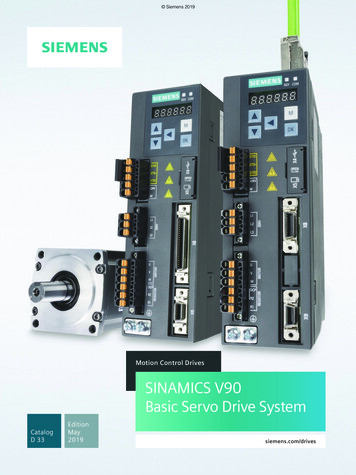
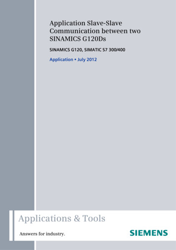
OperationWARNINGUse of braking resistorIf an unsuitable braking resistor is used, this could result in a fire and severe damage to people, property and equipment.Use an appropriate braking resistor and install it correctly.The temperature of a braking resistor increases significantly during operation. Avoid coming into direct contact with brakingresistors.WARNINGHot surfaceDuring operation and for a short time after switching-off the inverter, the marked surfaces of the inverter can reach a hightemperature. Avoid coming into direct contact with these surfaces.RepairWARNINGRepair and replacement of equipmentRepairs on equipment may only be carried out by Siemens Service, by repair centers authorized by Siemens or byauthorized personnel who are thoroughly acquainted with all the warnings and operating procedures contained in thismanual.Any defective parts or components must be replaced using parts contained in the relevant spare parts lists.Disconnect the power supply before opening the equipment for access.2Installation2.1Mechanical installationMounting orientation and clearanceGetting StartedA5E34560220-002, 09/20147
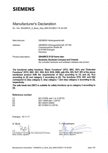
Outline dimensions(Unit: SE245216264.5209118.5Height of frame sizes with fan(s)Depth inside the cabinet for push-through mountingDepth of Flat Plate inverter (400 V 0.75 kW variant only)Drill patterns(Unit: mm)WHW1H1H2ØScrewTightening torqueFSA79140---4.64 M41.8 Nm 10%FSB127135---4.64 M41.8 Nm 10%FSB*12510811817245.54.64 M41.8 Nm 10%FSC170140---5.84 M52.5 Nm 10%FSC*170116161197615.84 M52.5 Nm 10%FSD223166---5.84 M52.5 Nm 10%FSD*223142214222595.84 M52.5 Nm 10%FSE228206---5.84 M52.5 Nm 10%FSE*228182219282835.84 M52.5 Nm 10%* For push-through mounting only.For more information about the push-through mounting and the installation of the Flat Plate inverter, refer to the SINAMICSV20 Inverter Operating Instructions.2.2Electrical installationWARNINGRequirements for United States/Canadian installations (UL/cUL)Suitable for use on a circuit capable of delivering not more than 40000 rms Symmetrical Amperes, 480 Vac maximum for400 V variants of inverters or 240 Vac maximum for 230 V variants of inverters, when protected by UL/cUL-certified Class Jfuses or type E combination motor controllers. For each frame size A to E, use 75 C copper wire only.This equipment is capable of providing internal motor overload protection according to UL508C. In order to comply withUL508C, parameter P0610 must not be changed from its factory setting of 6.For Canadian (cUL) installations the inverter mains supply must be fitted with any external recommended suppressor withthe following features: Surge-protective devices; device shall be a Listed Surge-protective device (Category code VZCA and VZCA7) Rated nominal voltage 480/277 VAC (for 400 V variants) or 240 VAC (for 230 V variants), 50/60 Hz, three phase (for400 V variants) or single phase (for 230V variants) Clamping voltage VPR 2000 V (for 400 V variants) / 1000 V (for 230 V variants), IN 3 kA min, MCOV 508 VAC(for 400 V variants) / 264 VAC (for 230V variants), SCCR 40 kA Suitable for Type 1 or Type 2 SPD application Clamping shall be provided between phases and also between phase and ground8Getting StartedA5E34560220-002, 09/2014
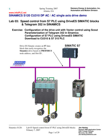
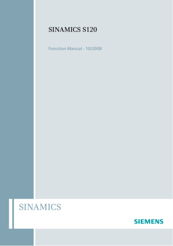
Wiring diagramNoteThe resistance of the potentiometer for each analog input must be 4.7 Ω.Getting StartedA5E34560220-002, 09/20149
Recommended fuse typesThis equipment is suitable for use in a power system up to 40000 symmetrical amperes (rms), for the maximum ratedvoltage 10% when protected by an appropriate standard fuse.Frame sizeRecommended fuse typeCE-compliant(Siemens)Frame sizeUL/cUL-compliantRecommended fuse typeCE-compliant(Siemens)400 V A3NA3805 (16 A) 15 A 600 VAC, class JA3NA3805 (16 A) 15 A 600 VAC, class JB3NA3807 (20 A) 20 A 600 VAC, class JB3NA3812 (32 A) 30 A 600 VAC, class JC3NA3812 (32 A) 30 A 600 VAC, class JC3NA3820 (50 A) 50 A 600 VAC, class JDE-60 A 600 VAC, class J18.5 kW-70 A 600 VAC, class J22 kW-80 A 600 VAC, class J230 VUL/cUL-compliantRecommended motor controller typesFrame size400 VAB230 VType E combination motor controllersOrder number (Siemens)Voltage (V)Current (A)Power (hp)0.373RV20 11-1CA104801.8 to 2.51.00.553RV20 11-1DA104802.2 to 3.21.50.753RV20 11-1EA104802.8 to 4.02.01.13RV20 11-1FA104803.5 to 5.03.01.53RV20 11-1HA104805.5 to 8.05.02.23RV20 11-1JA104807.0 to 10.05.03.03RV20 11-1KA104809.0 to 12.57.54.03RV20 21-4AA1048011.0 to 16.010.0C5.53RV20 21-4BA1048014.0 to 20.010.0A0.123RV20 11-1DA10230/2402.2 to 3.20.750.253RV20 11-1FA10230/2403.5 to 5.01.00.373RV20 11-1HA10230/2405.5 to 8.02.00.553RV20 11-1JA10230/2407.0 to 10.03.00.753RV20 11-1KA10230/2409.0 to 12.53.01.13RV20 21-4BA10230/24014.0 to 20.05.01.53RV20 21-4CA10230/24017.0 to 22.07.52.23RV20 21-4EA10230/24027.0 to 32.010.03.03RV10 31-4FA10230/24028.0 to 40.020.0BC10Inverter power rating (kW)Getting StartedA5E34560220-002, 09/2014
Terminal descriptionNoteTo disconnect the built-in EMC filter on FSE, you can use a Pozidriv or flat-bit screwdriver to remove the EMC screw.NOTICEDamage to the mains terminalsDuring electrical installation of the inverter frame sizes A and B, use stranded cables or cables with UL/cUL-certified,suitable fork crimps rather than solid cables or cables with pin crimps for mains terminal connection; for frame size E, usecables with UL/cUL-certified ring crimps for the mains terminal connections.Getting StartedA5E34560220-002, 09/201411
Recommended cable cross-sections and screw tightening torquesFramesizeRated output powerMains and PE terminalsMotor / DC / braking resistor / output earthterminalsCable crosssection*Screw tightening torque Cable crosssection*(tolerance: 10%)Screw tightening torque(tolerance: 10%)1.0 mm2(12)1.0 Nm1.0 Nm400 VA0.37 kW to 0.75 kWBC1.1 kW to 2.2 kW1.53.0 kW to 4.0 kW6 mm2 (10)5.5 kWDmm213.5(12)mm2(6)1.52.4 Nm(10)mm2(12)6 mm2 (10)1.5 Nm8.5mm2(8)2.4 Nm6.0mm2(10)7.5 kW6.011 kW to 15 kW10 mm2(6)10 mm2 (6)18.5 kW (HO)10 mm2 (6)6 mm2 (8)22 kW (LO)16 mm2 (4)10 mm2 (6)22 kW (HO)16mm2(4)10 mm2 (6)30 kW (LO)25 mm2 (3)16 mm2 (4)0.12 kW to 0.25 kW1.5 mm2 (12)0.37 kW to 0.55 kW2.5mm20.75 kW4.0 mm2 (12)B1.1 kW to 1.5 kW6.0 mm2 ** (10)C2.2 kW to 3.0 kW10 mm2 (6)Emm21.0 mm2 (12)230 VA1.0 Nm1.0 mm2 (12)1.0 Nm2.5 mm2 (10)1.5 Nm4.0 mm2 (8)2.4 Nm(12)2.4 Nm* Data in brackets indicate the corresponding AWG values.** With a UL/cUL-certified, suitable fork crimpMaximum motor cable lengthsInverter variant Maximum cable lengthWithout output reactor or external EMC filterWith output reactorWith external EMCfilter 1)400 VUnshieldedShieldedEMC compliant(RE/CE C3) 2)UnshieldedShieldedEMC compliant(RE/CE C2) 3)FSA50 m25 m10 m150 m150 m25 mFSB to FSD50 m25 m25 m150 m150 m25 mFSE100 m50 m50 m300 m200 m25 m230 VUnshieldedShieldedEMC compliant(RE/CE C2) 2)UnshieldedShieldedEMC compliant(RE/CE C2) 3)FSA50 m25 m10 m200 m200 m5mFSB to FSC50 m25 m25 m200 m200 m5m1)2)3)As specified in Section B.1.8 of the SINAMICS V20 Inverter Operating Instructions.For filtered variants only. RE/CE C3 refers to EMC compliance to EN61800-3 Category C3 for Radiated and ConductedEmissions; RE/CE C2 refers to EMC compliance to EN61800-3 Category C2 for Radiated and Conducted Emissions.For unfiltered variants only.Permissible I/O terminal cable cross-sectionsCable typePermissible cable cross-sectionSolid or stranded cable0.5 mm2 to 1.5 mm2Ferrule with insulating sleeve0.25 mm212Getting StartedA5E34560220-002, 09/2014
2.3Technical specificationsThree phase AC 400 V invertersSingle phase AC 230 V invertersLine supply characteristicsVoltage range380 V to 480 V AC (tolerance: -15 % to 10 %)200 V to 240 V AC (tolerance: -10 % to 10 %)47 Hz to 63 Hz47 Hz to 63 HzCurrent derating exists at the input voltages /switching frequencies higher than 400 V / 4kHz. *Current derating exists at the input voltages /switching frequencies higher than 230 V / 8kHz. *Overvoltage categoryEN 60664-1 Category IIIPermissible supplyconfigurationTN, TT, IT **, TT earthed lineSupply environmentSecond environment (private power network) *Overload currentRated power 0.12 kW to 15 kWTN, TT150% rated for 60 secondsRated power 18.5 kW (HO)/22 kW (HO)Rated power 22 kW (LO)/30 kW (LO)110% rated for 60 secondsEnvironmental conditionsSurrounding airtemperature0 C to 40 C: without deratingStorage temperature- 40 C to 70 CProtection classIP 20Maximum humiditylevel95% (non-condensing)Shock and vibrationLong-term storage in the transport packaging according to EN 60721-3-1 Class 1M2Operating altitudeUp to 4000 m above sea level40 C to 60 C: with derating (UL/cUL-compliant: 40 C to 50 C: with derating)*Transport in the transport packaging according to EN 60721-3-2 Class 2M3Vibration during operation according to EN 60721-3-3 Class 3M21000 m to 4000 m: output current derating *2000 m to 4000 m: input voltage derating *EnvironmentalclassesPollution degree: 2Solid particles: class 3S2Chemical gases: class 3C2 (SO2, H2S)Climate class: 3K3* For more information, refer to the SINAMICS V20 Inverter Operating Instructions.** Note that only unfiltered variants can be operated on IT power system; to operate FSE filtered variant on IT power supply, make sure you remove the screw for the EMC filter.Getting StartedA5E34560220-002, 09/201413
3CommissioningFor more information about parameters, faults, and alarms, refer to Appendix A of the English or Chinese version of thisdocument.3.1The built-in Basic Operator Panel (BOP)Button functionsStops the inverterSingle pressOFF1 stop reaction in HAND mode.Double press ( 2 s) or longpress ( 3 s)OFF2 stop reaction: the inverter allows the motor to coast to a standstillwithout using any ramp-down timings.Starts the inverter in HAND / JOG mode.Multi-function button Short press ( 2 s) Enters the parameter setting menu or moves to the next screenRestarts the digit by digit editing on the selected itemReturns to the fault code displayPress twice in digit by digit editing to discard change and returnLong press ( 2 s) Returns to the status screenEnters the setup menuShort press (
1.1.4 Industrial security Note Industrial security Siemens provides products and solutions with industrial security functions that support the secure operation of plants, solutions, machines, equipment and/or networks. They are important components in a holistic industrial security concept.