Transcription
Cat. No. 01021161Rev. A 10/16/08DCO # 010703Installation,Operating andServiceInstructionsCULLIGAN Global Electronic (GBE)Softener & Filter ControllerFor Commercial/Industrial ApplicationsModels from 2008 2008 Culligan International Com pa nyPrinted in USA
Read this Manual FirstBefore you operate the Culligan Global Controller, read this manual to become familiar with the device andits capabilities.Watch for Special ParagraphsPlease read the special paragraphs in this manual. Examples are shown below.NOTEA Note provides information or highlights a procedure.CAUTIONA Caution tells how failing to follow instructions might causeinjury or damage the equipment in some way.About this ManualContentsThis manual: familiarizes the operator with the equipment explains installation and setup procedures provides basic programming information explains the various modes of operation gives specifications and troubleshooting informationWARNING! Electrical shock hazard! Unplug the unit before removing the cover or accessing any internal control parts.WARNING! This device complies with part 15 of the FCC rules subject to the two following conditions: 1) This device maynot cause harmful interference 2) this device must accept all interference received including interference that may causeundesired operation.Caution! To reduce the risk of fire, use only No. 26 AWG or larger telecommunicaitons line cord.This equipment complies with Part 15 of the FCC rules. Any changes or modifications not expressly approvedby the manufacturer could void the user’s authority to operate the equipment. Changes or modifications notexpressly approved by the party responsible for compliance could void the user’s authority to operatethe equipment.Products manufactured and marketed by Culligan International Company (Culligan) and its affiliates are protected by patents issued or pending in the United States and other countries. Culligan reserves the right to change the specifications referred to in this literature at any time,without prior notice. Culligan, AquaSensor, Tripl-Hull, and SoftMinder are trademarks of Culligan International Company or its affiliates.The product is covered by the following patents:Softener and/or filter: US 5073255, 5273070, 6457698, 4534867: Israel 095754Sensor option: US 5699272Other US and foreign patents pending.iCULLIGAN GLOBAL ELECTRONIC CONTROLLER
Installation,Operating andServiceInstructionsCULLIGAN Global electronic (GBE) softener& filter controllerTable of Contents . . . . . . . . . . . . . . . PageImportant Safety Information. iController Features.1-2Operation.3Installation.4-6Wiring Schematics.7-17Circuit Board Layout.7Transformer.8-9Brine Refill Valve.10Communication Cable.11Progressive/ Parallel Flow.12Alternating.13Flow Meters.14Aqua-Sensor.15Aux Outputs.16Aux Input.17Programming.18-20Key Pad Operation . .19-20Overview.21Commercial Setup.22First Time Setup.23-27Customizing the Setup.28-32Progressive Flow.29Regeneration.30Cycle Times.31Regeneration Triggers.32Installation of Accessories.33-45Aqua-Sensor.33Beeper Mode.33Smart brine Tank Sensor.34Wireless Remote.35-37Modem.37-41Low Meter.41Progressive Flow.41-42Brine Reclaim.42-43Service Phone Number .44Auxiliary Boards.46-48Manual Regeneration.49Manual Cycling.50System Information.51-52Error & Alert Codes.53Diagnostics / Statistics.54-57Check Sensors.55-57Menu Lockout.58Menu Flow Chart.59-62Appendix A - Meter K-Factors.63Appendix B - Parts & Accessories.64Appendix C - PLC Output.65-68Appendix D - Control Settings.69Index.70TABLE OF CONTENTSii
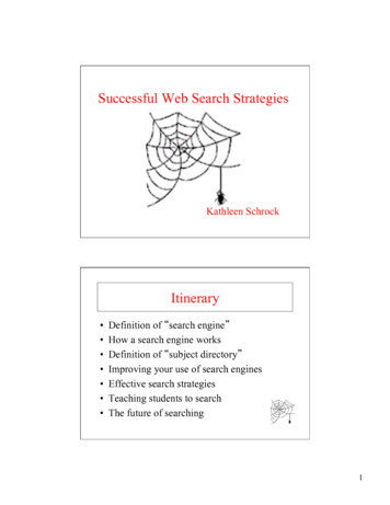
Controller FeaturesThe Culligan Global Electronic control (GBE) primary function is toinitiate and control the regeneration process via methods that are mostconvenient and cost effective for the customer while offering manyoperational features and benefits. The controller is designed to operate awide range of existing and new softener and filtration valves.Take control of your system and your productivityThe Culligan Global Electronic Controller (GBE) is an advanced designengineered to handle regeneration and monitoring of your watertreatment equipment. It offers powerful programming options thatcan be used to operate and monitor any softener or filter system. Italso provides sensing capabilities, expanded communications and amultifunction keypad—all in one simple to use unit.GBE Controller Features dvanced Lighted OLED DisplayAThe user is guided through brightly lit graphical menu screenswith clear, multi-line, full text prompts Membrane KeypadThe keypad uses sealed contacts for programming. No buttons to get dirty Program BeeperEmits an audible beep when keys are depressed to help identifyvalid (short beep) or invalid (3 short beeps) pushes. Can beenabled or disabled. ower SourcePElectrical power required is 24 Volt 50/60 Hz AC current. A ULlisted plug-in transformer (120V/24V) is provided.Figure 1 ime of Day TDisplays current time of day in either 12-hour or 24 hour format eal Time Clock with a 5 Year Battery Back-up RKeeps accurate time even during a power outage. Updatesautomatically when the GBE is equipped with optional modemcapabilityFigure 2 nglish or Metric ValuesEDisplays can be set to either English or Metric Regeneration IntervalProvides the ability to initiate a time clock regeneration based on a number of days (1 to 99) or a specificday of the week. egeneration Start DelayRAllows a user determined number of hours (0-9) to be set for the purpose of increasing the amount oftime between regenerations in a multi unit installation. Auxiliary InputCapable of accepting a remote signal from a dry contact device such as an operator push button for thepurpose of initiating a regeneration sequence uxiliary Output on AlarmACapable of sending a signal when an alarm/error is recognized Expansion Board for Additional OutputsoControl blocking valvesoControl external solenoids or chemical feeders1 CULLIGAN GLOBAL ELECTRONIC CONTROLLER
Controller Features Progressive Flow Trip PointAllows multiple tank systems operating with flow meters to bring tanks on-line or off-line as facility flowdemands increase or decrease M ultiple Unit CommunicationA communication cable interconnects multiple units to operate the controller in the Progressive Flowmode and prohibits them from regenerating at the same time. DiagnosticsThe user can check the operation of sensors, progressive flow communication, motor positions, or anoptional wireless display Transformer is UL and CUL ListedRoHS CompliantOptional GBE Features low Meter/Sensor InputFSupports various types of Hall effect flow sensors using a programmable “K” factor to initiate aregeneration sequence quaSensor InputASupports the patented digital Culligan AquaSensor technology used to efficiently initiate and control aregeneration sequence Telephone ModemoCalls in reports on regenerations and alarm conditionsoAutomatically updates time and date when calling inoAutomatically checks for and installs and firmware updates when calling in Remote Display WirelessDisplays the current status of the unit. It can be located up to 200 feet away from the GBE controller(depending on building and interference). The telephone modem can optionally be installed in the remotedisplay mart Brine Tank ProbeSThis probe monitors conditions inside the brine tank.oPredicts when more salt is neededoDetects the presence of a salt bridgeoDetects eductor line pluggingoSignals brine tank overfilling conditionCONTROLLER FEATURES 2
OperationModes of OperationTime ClockThe controller will initiate a regeneration based upon a time schedule of intervals of days (i.e., every 3 days) oron a specific day of week schedule (i.e., Mondays, Wednesdays and Saturdays). Because regeneration willoccur at the prescribed schedule regardless of water use, this method is usually the most inefficient method ofwater softener operation.Flow Meter/SensorWhen a flow meter or sensor is connected to the controller circuit board, the controller has the ability to measurethe amount of water treated and initiate a regeneration sequence based upon the gallon capacity of the watertreatment equipment. The controller can delay the regeneration signal until a convenient time of day (known asa delayed regeneration) or act and initiate the regeneration sequence as soon as the signal is received (knownas immediate regeneration).When installing an alternating duplex system (one tank on-line, the other in standby), only one flow measuringdevice is required to be installed in the common outlet header of the system. Parallel systems (multiple tank systems, all on-line simultaneously) require one flow device for each mineral tank in the system.This method is a proven, cost effective means to operate a water softening system.Aqua-Sensor (Softener use only)The Aqua-Sensor detects when a softener resin bed has reached its point of exhaustion and, as a result, initiatea regeneration sequence. This is the most cost-effective method of operation and may be combined with any ofthe operational modes previously described.Progressive FlowThe Progressive Flow mode is used with up to six and as few as two mineral tanks in a system. It allows morethan one tank in a system to either be on-line or off-line depending upon the downstream flow demand. If flowdemand is greater than the flow capability of the tank on-line, another tank can be brought on-line to help satisfythe excess demand. Once the demand has decreased, the second tank is returned to a standby mode and thesystem reverts to just one tank on-line providing treated water.The progressive flow mode of operation relies on a user programmable set point or Trip Point. The Trip Pointis a unit of flow (gallons or liters) on a per minute basis. Once attained the trip point will cause the second unit(in multiple resin tank system) to come on-line. Each additional tank in the system will subsequently be broughton-line as multiples of the trip point are attained. (Example: a 3 tank system with a trip point of 50 gpm will bringtwo tanks on-line once the facility flow demands is equal to or greater than the 50 gpm trip point. Should the flowdemand reach 100 gpm or more, the third tank shall be brought on-line.)Additional tanks shall be returned to stand-by once the facility flow demand is 95% of the trip point for twotank systems, 95% of 2X the trip point for triplex systems and 95% of 3X the trip point for quad systems, andremains there for 60 seconds.Utilizing the progressive flow feature may allow the owner to use smaller units, resulting in the potential forreduced capital and operation costs.Differential Pressure (Filters only)When combined with an optional differential pressure device, the Culligan MVP controller has the ability toinitiate a backwashing sequence when the pressure differential across the media bed reaches a preset amount(usually 8 to 10 psi).3CULLIGAN GLOBAL ELECTRONIC CONTROLLER
InstallationELECTRICAL INSTALLATIONCAUTION!Observe the precautions listed below before electrical installation of your GBE controller.Failure to do so may cause permanent damage to the controller.1.Follow the local electrical code requirements.2.Be sure electrical power is off and disconnected at the source before completing any wiring/cablingconnections.3.Provide a dedicated 120-volt circuit for the GBE system to ensure maximum electrical protection.4.DO NOT include the GBE wiring cables in any conduit or raceway containing other 120-volt or highercircuits.5.Maintain a distance of at least 10 feet between the GBE controller and any electrical distributionpanels, raceways carrying 300 volts or more, and electrical motors of 1 horsepower or more.6.Use the cabling provided. Failure to do so may effect performance of the GBE controller adversely.Note: One transformer is required for each controller in the system. Do not attempt to operate multiplecontrollers without a dedicated transformer for each or your system will experience operationaldifficulties.Installation4
InstallationWIRING PROCEDURES AND DIAGRAMSPreparation1. Loosen the screws or latches securing the controller access cover (Figure 3 or 4) on each controllerprovided.2. Using a small screwdriver, loosen all the terminal strip binding screws on the main circuit board that donot contain wires by turning counterclockwise until the wire clamp has been fully opened (see Figure 5).Figure 4Figure 3Figure 55CULLIGAN GLOBAL ELECTRONIC CONTROLLER
InstallationCable RoutingAll input and output connections to the circuit board are 24 volt or less.Although the cables do not have to be run in conduit, it is necessary that long runs of cable be supported orprotected by strapping them to the equipment piping. If conduit will be used to route the shielded cables, threefactors must be considered:1. DO NOT share the same conduit or raceway with 120 volt or higher circuits.2. Keep cables at least 6 inches away from 120 volt or higher electrical circuits.3. GROUND the conduit (if metallic) to a known “earth ground” location.A series of holes are located on the sides of the controller (see Figure 6 and 7). Strain relief fittings are providedwith the controller enclosure for interconnecting wiring. Install the plastic fittings as needed. Remove the compression nut and rubber sleeve from each fitting. Prior to connection of the cable wires to the circuit board, slidethe compression nut and sleeve over the cable for the wiring connections. When wiring is completed, apply asmall amount of silicone to the rubber sleeve and reassemble. This will assure all wiring is secure and assistin making the tightening of the fitting easier. Insert the plugs provided to block any holes not used for wiring orother accessories.Right Side ViewLeft Side ViewBrine Reclaim Solenoid(optional)Input Connectionfor Flow SensorOutput Connectionfor RemoteAccessoriesInput Connectionfor RemoteAccessories24 Volt PowerInput ConnectionBrine Reclaim Solenoid(optional)Figure 6Brine Refill ValveBlocking Solenoid forAlternating OperationFigure 7Installation6
SchematicGBE Circuit Board Layout–FrontOLED DisplayBatteryCR2032 (Postitive Side Up)Keypad connectorFigure 8GBE Circuit Board Layout–BackData portPhone lineconnection(optional)Future useDo not connectanything to these.Motor position cableMultiple unit jumperAqua-Sensorcable (optional)Communication cable (optional)Flow meter cable(optional)Smart Brine Tank cable (optional)External regenerationsignal connection (optional)MotorconnectionBlocking valveconnection (optional)Programmable outputs (optional)Figure 97CULLIGAN GLOBAL ELECTRONIC CONTROLLERPower cablefrom transformer
SchematicOutputsCAUTIONConnecting 24V to the 2.5vconnection on the circuit boardwill damage the circuit board.The circuit board supports four outputs:Motor control (DC Motor)Blocking valve (Use Aux Out 4) Four programmable auxiliary outputs (Aux Out 1through 4) Controller interface (communication between multiple controllers) (RS485).Note: I f you are using Aqua-Sensor, you should run the 2.5v wiring now as the cable is run through the same cord grip.See page 15 for details.1.2.3.4.5.6.Locate the power cord among the controller parts. It has a white connector on one end and two spade connectors on theother.Locate the cord grip among the parts.To assemble the power cord, first run the cord grip nut over the spade terminal end of the power cord.Next, run the spade terminals through a hole in the side of the controller FROM THE INSIDE. See figure 10.Finally, run the cable through the bottom end of the cord grip, and assemble the grip to the controller wall.Plug the board connector to the board where it says “24v”. The connector has four (4) connections but only two wires areconnected. The other end of the power cord (with spade terminals) should be connected to the two 24VAC terminals onthe transformer (see figure 12).DO NOT PLUG THE TRANSFORMER INTO THE WALL UNTIL ALL WIRING IS COMPLETED.Repeat the process for any additional units in the system.Schematic8
Schematic24V TransformerThe GBE control is powered by a 24V/50VA transformer. If there are multiple controls in the system beinginstalled, each control will require its own transformer. It is recommended that the transformer be plugged into adedicated 120V circuit.CAUTIONConnecting 24V to the 2.5V connection on the circuit board will damage the circuit board1. Connect one wire from the 24V cable to the outermost 24VAC transformer screw terminal(Reference Figure 12). The other end of the wire should be connected to one of the 24V terminalson the GBE control circuit board (Figure 11) by way of the white connector.2. Repeat the process for the other 24V power supply wire attaching the second wire to the oppositeterminal on the transformer and next to the other wire connected to the 24V pins on the GBE board.24V Power ConnectionMETAL TABSConnect to white connectoron main power cordIf using Aqua-Sensor,plug metal tabs at endof cord into connectorFigure 10POWER SUPPLYONE transformer is required for each Control24VAC PowerTerminals2.5VAC Aqua-SensorPower TerminalsTransformer connectionFigure 119CULLIGAN GLOBAL ELECTRONIC CONTROLLERFigure 12
SchematicBrine Refill Valve Wiring*This only applies to Culligan CSM Softeners.1. Installation of the solenoid coil and connectorLocate the solenoid coil and connector cord. Assemble itto the brine refill valve as shown in Figure 13.SolenoidCoilScrewPlasticSpacerFigure 132. Installation of the cord gripRemove the hole plug from the left side of the MVPcontroller enclosure. Locate the cord grip fitting and nut.Assemble them through the open hole and thread thesolenoid coil cord through the cord grip fitting as shownin Figure 14. Tighten the cord grip onto the cord.Figure 14LCD3. WiringWire the valve to Aux Out 2 as shown in the diagram inFigure 15. The wires can be trimmed to a suitable length.MVPCIRCUIT BOARDP9 RIM OFFGREEN WIREFigure 15Schematic 10
SchematicCommunication Cable - Multiple UnitsNOTE: Disregard this information and proceed to flow sensor schematic (optional) information when installingsingle tank configurations.Multiple units require a communication cable between each unit. Refer to the table below for the cable type, partnumber and quantity required. Cables are attached to the RS485 terminal of the circuit board.Table 2SystemConfigurationCable Part NumberQty of Cablesrequired“Kit” Part NumberQty of blockingsolenoids used.Duplex Alternating010163421010163692Duplex Parallel010163271N/A0Triplex Parallel010163272N/A0Duplex Progressive010163271010163332Triplex Progressive010163272010163343Multiple units can be set up as progressive flow, alternating or parallel operation. Refer to the instructions andschematics below and on the following pages for connection to the circuit board.Most multiple tank configurations will also require blocking valves (with the exception of the Hi-Flo 3e softener).These are used to hold tanks offline until needed. Based on the chart above, you can determine how manyblocking solenoids are used. These solenoids are included in the alternating and progressive flow kits.Blocking Solenoid Connection (used on Alternating and Progressive flow systems)The solenoid valve wiring attaches to the Aux Out 4 output connection on the auxiliary circuit board. SeeFigure 16 .SOLFigure 1611 CULLIGAN GLOBAL ELECTRONIC CONTROLLER
SchematicProgressive Flow or Parallel FlowIMPORTANTSetting the Jumpers for Progressive FlowFor progressive flow to operate properly, the first and last units musthave the jumpers set to pins 1 and 2 (see figure at right). All middleunits should have the jumpers on pins 2 and 3 (see figure at right).The diagram below (figure 17) shows duplex connections. Repeat theconnections on any additional systems.Communication Cable 01016327123Jumper location forfirst and last units(end units).Jumper location formiddle units.To Additional Units(if necessary)JumperLocationFlow MeterUnit 1Flow MeterUnit 2Figure 17Progressive/Parallel Communication Cable 01016327To RS 485 Comm Porton GBE Circuit Board, #1To RS 485 Comm Porton GBE Circuit Board, #2PARALLELAdditional communication cableconnections are used when thereare 3 or more controls. Connectend of 2nd-(01016327) cableto this connector and other end ofcable to RS 485 Comm Port on3rd GBE Circuit Board.CABLE 01016327Schematic 12
SchematicDuplex Alternating with Meter optionCommunication Cable 01016342Unit 1Unit 2Flow meterFigure 18For triplex, quad, etc alternating, you must use a meter on each unit and connect the same way asprogressive flow.Duplex Alternating Cable 01016342To RS 485Comm Porton GBE Ciruit Board, #2To RS 485Comm Porton GBE Ciruit Board, #1To Flow Meter Connection(on GBE Circuit Board).Flow Meter Connector(from meter).DUPLEX ALTERNATINGCABLE 0101634213 CULLIGAN GLOBAL ELECTRONIC CONTROLLERTo Flow Meter Connectionon GBE Circuit Board.
SchematicFlow Sensor Meter Connections (Optional)The GBE Controller is capable of detecting the signal from a Hall effect sensor device to provide flow rate information, totalization and volume based regeneration initiation.There are several different types of flow measuring devices and differences in the wiring of the devices to theGBE circuit board do exist. Refer to the drawings below.For all but duplex alternating, a meter needs to be connected to each circuit board at the location shown belowin the drawing. For duplex alternating meter connection, please refer back to page 13, Duplex Alternating withmeter option.SEE PAGE 41 FOR PROGRAMMING AND PAGE 63 FOR K FACTORS.Figure 19Signet2535 & 2536(optional)SeametricsPaddle Wheel(optional)BlackWhiteRedRedBlackWhiteBlack2" Autrol Turbine ectorlocated atend of 1010255 includedwith controller2"Clack Meter(optional)SINGLE OR PROGRESSIVESchematic 14
SchematicAqua-Sensor Schematic (Optional)The Aqua-Sensor device requires a 2.5 VAC power source. This source is provided via two of the posts on the24VAC/2.5VAC transformer (see figure 20). The two leads from the transformer are run through the same cablegrip as the 24VAC and then must be pushed into the white power connector for connection to the 2.5v powerpins on the GBE circuit board.The wire connector from the Aqua-Sensor probe is then routed through the included cable grip and plugged intothe Aqua-Sensor terminal on the GBE circuit board. See below.Aqua-SensorIf you are going to install an Aqua-Sensor, you can set up the 2.5V power now.1. Locate the power cord packed with the Aqua-Sensor. It has two spade terminals on one end of the cableand two metal “slip in” tabs on the other.2. Locate the cord grip.3. The cable can be run through the cable grip and wall from either end of the cable. Make sure the end withthe metal tabs goes INSIDE the controller. The spade terminals should be coming out the top end of thegrip.4. Locate the connector at the end of the power cord. You may have already plugged it into the board.5. Press the two metal tabs on the end of the power cord into the open slots on the connector. They will connect to the pins labeled “2.5V’ on the Base Board.The other end of the power cord with the spade terminalsshould be connected to the two 2.5VAC terminals on the transformer (see figure 20).CAUTION - Verify wiring from terminals to circuit board are correct before applying power tocontrol. 24vac power must not be applied to the 2.5 vac terminals of the circuit board.2.5V Aqua-Sensor Power ConnectionFigure 20BluePower to circuitboard 2.5VAConly requiredfor Aqua-SensorinstallationsMETAL TABSConnect to whiteconnector on mainpower cordPower to circuitboard 24V2.5V24VACon TRANSFORMER15 CULLIGAN GLOBAL ELECTRONIC CONTROLLERCAUTIONConnecting 24V to the 2.5Vconnection on the circuit boardwill damage the circuit board.BlackRedWhitePOWER SUPPLYONE transformer isrequired for each Control
SchematicAuxiliary Outputs (Optional)The Auxiliary Outputs - reference figure 21) are output triacs that can be programmed to provide power to a“normally open” (normally no power to auxiliary output until power required) or a “normally closed” contact (userchoice). These 24VAC outputs can be used for energizing a relay coil only. (2.1 Amp maximum power draw)Refer to the section on Programming (page 46) for additional information on the uses of this feature.43Figure 21Schematic 16
SchematicAuxiliary Input (Optional)One auxiliary input is provided for optional signal devices such as remote push buttons, differential pressureswitches, hardness monitors, turbid meters, etc. for the purpose of receiving a regeneration signal.Select an UN-POWERED contact within the remote device that will close when regeneration is desired. Theduration of the switch closure can be as low as 0 seconds; 6 seconds is the recommended minimum and defaultbut can be as long as 999 seconds. The contact must automatically open following the start of a regenerationsequence. Connect this contact to the Aux In terminal shown in Figure 22. The illustration below is an exampleof how to use an external source to initiate regeneration.Communication Cable01016327NCSOLNOSOLPOLE1CNCNOPOLE2C24V DPDTRELAYFigure 22DUPLEX ALTERNATING WITH EXTERNAL SOURCE17 CULLIGAN GLOBAL ELECTRONIC CONTROLLEREXTERNALSOURCERegen Signal
ProgrammingProgrammingThe programming process requires various types of data input. The following information pertains to calculatingthe softening capacity of the water softening system. Filters do not have a capacity setting so this section can beskipped when programming a filter.Capacity SettingsThe capacity of a water softener is determined by two factors; resin amount and water chemistry.Single Tank SystemsNormally a single tank system has enough resin capacity to soften water for a minimum period of 24 hours.Time of regeneration is usually set to occur very early in the morning or at a time when no softened water isrequired. This is because when the softener is regenerating, hard water is typically bypassed through the systemand into the facility if a demand for water if present.If regeneration is desired at a time of day when there is no water usage then the system must have a “reserve”capacity which must last an entire day if the regeneration signal (time clock, Aqua-Sensor and/or meter) occursat the beginning of the day. Subtract this reserve capacity from the total capacity to determine “capacity to signal”.Note: If the reserve capacity is more than 1/3 of the total capacity,a meter system may not reduce salt consumption relative toa timeclock system.Multiple Tank SystemsMultiple tank systems offer the benefit of continuous soft water supply. When using the Aqua-Sensor to initiatea regeneration sequence, the system capacity may be set for the maximum amount the system is capable ofproducing. However multiple tank systems using only water meters and or time clock as the basis for regeneration initiation are recommended to be set up with a 10% reserve capacity. The purpose of the reserve capacityin multiple tank systems is to allow for subtle changes in water chemistry. You will be able to get the reservecapacity during programming.Determining Batch Set PointTo determine the batch set point for programming the Culligan GBE controller, use the following formula:Total Capacity - Reserve CapacityGallons HardnessThe GBE will calculate this for you automatically. y
without prior notice. Culligan, AquaSensor, Tripl-Hull, and SoftMinder are tradem arks of Culligan International Com pany or its affiliates. The product is covered by the following patents: Softener and/or filter: US 5073255, 5273070, 6457698, 4534867: Israel 095754 Sensor option: US 5699272 Other US and foreign patents pending.