Transcription
C ATA L O GCOMMERCIAL & INDUSTRIALModels PS/IPSStainless Steel Double WallPositive Pressure Piping SystemsSelkirk Metalbestos Models PS and IPSare modular, prefabricated piping systemswhich embody flanged joints designedfor both quick assembly and pressuresealing capabilities.FEATURES PS/IPS Boiler Breeching Chimney Stack Engine Exhaust PS/IPS Grease Duct Food Service Venting
TABLE OF CONTENTSU.S. PATENTSCODE COMPLIANCESelkirk Metalbestos invented the Model PS concept (flanged end, weldedtube, V band) over 25 years ago and was granted the following patents.U.S. patents: 3902744, 4029343, 4029344When installed in accordance with its installation instructions, Model PS andIPS comply with the following codes:Model PS and IPS in sizes 5" through 48" diameters have been tested andListed (Safety Certified) by Underwriters Laboratories, Inc. (ULI) and bearsthe UL and/or c-UL logo signifying compliance with U.S. and/or Canadianstandards. UL Listing product categories include:(USA)Grease DuctBuilding Heating Appliance Chimney(Industrial) 1400 F ChimneyType L Vent (Model IPS only)(Canada) Grease Duct540 C (1000 F) Industrial Chimney760 C (1400 F) Industrial ChimneyUL file numbers for PS and IPS includeMH6673 and MH11382APPLICABLE MODEL PS/IPS REFERENCESBuilding Heating Appliance ChimneyUL103 NFPA211 NFPA31 NFPA37 ULC-S6041400 ChimneyUL103 NFPA211 FNFPA37Grease DuctUL1978 NFPA96Type L VentUL641 NFPA31ASSOCIATIONSSelkirk Metalbestos is proud to be an active member of the followingassociations:Model PS and IPS have been approved by the City of New York Departmentof Buildings, Materials and Equipment Acceptance Division under thefollowing MEA numbers:Model PSModel IPSBuilding HeatingAppliance ChimneyMEA 132-90MMEA 135-90M1400 F ChimneyMEA 133-90MMEA 181-90MGrease DuctMEA 134-90MMEA 134-90MTABLE OF CONTENTSUNDERWRITERS LABORATORIES LISTINGSNFPA (National Fire Protection Association)SBCCI (Southern Building Code Congress International)ICBO (International Conference of Building Officials)BOCA (Building Officials and Code Administrators)ICC (International Code Congress)U.S. Patents & UL Listings . . . . .inside front coverSystem Concept . . . . . . . . . . . . . . . . . . . . . . . . .1Exceeding the Requirements . . . . . . . . . . . . . . .1Guide to Component Parts . . . . . . . . . . . . . . . . .2Product Identification . . . . . . . . . . . . . . . . . . . .4Product Listings . . . . . . . . . . . . . . . . . . . . . . . . .4Joint Assembly Parts . . . . . . . . . . . . . . . . . . . . .5Sealants . . . . . . . . . . . . . . . . . . . . . . . . . . . . . .5Double Wall Pipe . . . . . . . . . . . . . . . . . . . . . . .7Adjustable/Variable Pipe . . . . . . . . . . . . . . . . . .7Double Wall Fittings . . . . . . . . . . . . . . . . . . .8-13Support/Guide Accessories . . . . . . . . . . . . . . .15Connection Accessories . . . . . . . . . . . . . . . .16-18Roof Penetrations . . . . . . . . . . . . . . . . . . .19-21Terminations . . . . . . . . . . . . . . . . . . . . . . .22-24Miscellaneous . . . . . . . . . . . . . . . . . . . . . . . . .25Special Parts . . . . . . . . . . . . . . . . . . . . . . . . . .26Weight Information . . . . . . . . . . . . . . . . . .27-29Technical Data . . . . . . . . . . . . . . . . . . . . . . . .30Warranty Statements . . . . . . . . .inside back cover
SYSTEM CONCEPTSelkirk Metalbestos Model PS and IPS are modular, prefabricated pipingsystems which embody flanged joints designed for both quick assembly andpressure-sealing capabilities. They offer a combination of insulated pipingcomponents as well as the structural accessories needed for support andattachment to building structures. Expansion joints are available both ingasket designs and in pressure tight, all-welded bellows designs.Exceeding the RequirementsStandard gas-carrying piping parts are usable for a wide variety ofapplications:Leak Tests Chimneys and stacks for all types of building heating equipment. Chimneys for industrial ovens, furnaces, and processing equipment. Exhaust piping for engines or turbine units. Ducting in restaurants for compliance with Type 1 hood requirements. Ducting for heated air and combustion products. Ducting for light duty pollution control equipment. Venting for engine exhaust and other shipboard systems. Venting for offshore drilling rigs.Selkirk Metalbestos, inventors of thepositive pressure system concept, farexceeds the requirements of codes andother manufacturers. Results of our testingprograms illustrate this fact.Selkirk Metalbestos conducted systempressure testing against leakage in thepresence of UL inspectors, and results ofthese tests are impressive. Using the OSHAoccupation standard-of-leakage rate of 50parts per million over an eight hour periodas criterion for acceptance, Selkirk wastested to a leakage rate of only .144 partsper million, or three-tenths of one percent(.3%) of the maximum allowable leakage.Complete Line of FittingsSeismic TestsModel PS and IPS are available ineighteen sizes, from 5" I.D. to48" I.D. Fittings includevarious elbows, tees, supportsand terminations, as well as avariety of accessory fittingsdesigned to make installationsimple and quick.We further demonstrated the superiority of the Model PS and IPS concept byconducting seismic load tests. These tests proved the structural integrity ofour products under severe stress by showing that a guyed stack measuring20 inches in diameter and exceeding 10 feet above the guying location(installed in strict accordance with the UL103 Listing) could withstand therigors of all Seismic Zones.Each component is shippedcomplete and ready for installation. Eachordered part includes Inner Vee Bands, OuterChannel Bands and all the necessary hardware.Structural TestsSelkirk Metalbestos recently tested for greater freestanding limits(termination height above a guide point). These tests, simulating stackperformance under 110 mph wind conditions, again demonstrated thesuperiority of Selkirk Metalbestos products.All items included with each order are listed in this catalog under the partdescription.Skin Temperature Rise TestsAmong other things, UL103 covers the temperature rise limits of thesurrounding combustible materials in an unenclosed chimney installation andit defines the test set-up to measure the actual temperature rise of thosematerials at the OEM recommended clearances. Our published Model IPS skintemperatures were obtained during these tests.1
GUIDE TO COMPONENT PARTSProductCodePageJoint Assembly PartsVee BandOverlapping- Vee BandChannel BandHalf Channel BandLow Temperature SealantHigh Temperature table/Variable Pipe30" Adjustable Pipe18" Adjustable PipeBellows Joint30" Variable Pipe18" Variable PipeAG30AG18BJVL30VL1877888Double Wall Fittings90 Tee90 Tee - Grease45 Tee - Lateral90 WyeMTGMTJLJY89910Double Wall Pipe60" Pipe Length42" Pipe Length30" Pipe Length18" Pipe Length2
GUIDE TO COMPONENT PARTSProductCodePageDouble Wall Fittings (cont)Drain Tee CapClean Out Tee Cap15 Elbow30 Elbow45 Elbow90 ElbowTapered IncreaserStep IncreaserDrain 14Suppot/Guide AccessoriesHalf Angle RingFull Angle RingPlate Support AssemblyWall Support AssemblyWall Guide AssemblyFloor Guide AssemblyHRFRPAWAWGFG151515151616Connection AccessoriesBoiler KitSeal RingFlange AdapterClamp FlangeFlanged Hood TransitionUnflanged Hood TransitionFan eRoof PenetrationsStorm CollarTall FlashingPitched Tall FlashingVentilated ThimbleVentilated Tall FlashingVentilated Storm CollarVentilated Thimble AssemblyVentilated Support AssemblyPitched Ventilated TerminationsClosure RingChimney TopStack CapExit ConeFlip TopMiter CutCRCTSKECFLMC222223232424MiscellaneousExplosion Relief ValveGuy SectionGuy TensionerERGSGT252525Note: For details on parts usage, refer to theSelkirk Metalbestos installationinstructions.Copies are available from SM field service representatives and regional offices.3
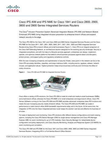
PRODUCT IDENTIFICATIONModel PS vs. Model IPSPS1IPSC1IPSC223IPSC44Fiber insulation increases the diameter of the outer wall on Model IPSC2 and IPSC4 pipe and fittings. Shown in this sequence is the same 8-inchdiameter inner pipe. (Photo 1) Without insulation the outside diameter of the pipe is 10-inches. (Photo 2) This is also true of the same pipe with a 1-inch layer of insulation. (Photo 3) However, the same 8-inch pipe with 2-inch insulation results in an outside diameter of 12 inches. (Photo 4)Adding 4 inches of fiber insulation makes the diameter of the outer wall 16 inches.Understanding Product Codes and Part NumbersAll parts manufactured by Selkirk Metalbestos are identified by a series of numbers and letters which describe their makeup and function.Here is how to interpret the Part Number designation for Model PS and IPS products.1. It begins with the pipe or fitting's Internal Diameter(in inches) such as 8, 22, 36, etc.2. This is followed by the Model designation, P for airinsulated (Model PS), or IP for parts that are fiberinsulated (Model IPSC1, C2 or C4).3. Next, is the product's Material designation, such as 316 or304/304. The first item indicates the makeup of the innerliner, while the second half indicates the material contentof the outer wall, if stainless. If aluminized outer, the PartNumber indicates inner material only.4. Then, following a long dash, the product's Code name islisted, such as AG30, JY, or MVT. If the product is airinsulated, the product identification ends with this Code.(For Product Code listings, refer to page 2.)5. Finally, when a product is fiber insulated, a designation isadded at the end to indicate Insulation Thickness. C1means a thickness of 1 -inch; C2, 2-inches; and C4, 4inches.(For comparison, see photos above.)Thus, the Ordered Part Number for a 30-inch Adjustable Pipe, with a 6-inch I.D., made of 304 Stainless Steel inner and Aluminized Steel outer,packed with 2-inch fiber insulation, is listed:6IP304- AG30C2** Note: For products with reduction or increaser parts, the Part Number changes as follows:MT and JL - Diameter of Body listed in front of Model P or IP.Diameter of Snout listed in front of Code designationOT and OS - Smaller diameter listed first (before Model designation)Larger diameter listed before Code designationExample - For a Manifold Tee with a 42" dia. Body and 30" dia. Snout:Example - For a Tapered Increaser with an 8" to 16"dia. Body:42P304-30MT48P304-160T
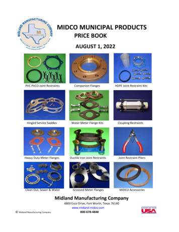
JOINT ASSEMBLY PARTSVeeBandOverlappingVee BandChannelBandHalf ChannelBandCode: VBCode: OVBCode: CBCode: HCBVee Band for connectingthe inner 1/2 inch rolledflanges. Capable of holding60" w.c. of pressure whenproperly installed.New Vee Band usedin lieu of VB in highpressure/turbulentapplications. Must beordered separately.Used to seal theOuter Jackets of twoadjoining components.Used to seal the Outer Jacketsof two adjoining componentswhen the VB must remainopen (such as PA's).(CB height is 43/4 inches)(HCB height is 21/16 inches)Materials Available:All Stainless ConstructionMaterials Available:All Stainless ConstructionMaterials Available:Aluminized Steel 304 316Materials Available:Aluminized Steel316Notes:Notes:1. 5", 6", 8", and 48" diameter VB's are a two-piece design.10" through 36" diameter VB's are a one-piece design.2. All OVB's are a two-piece design.3. Model PS part used for all IPS applications.1. Fiber insulation provided for IPS models.Low TemperatureSealantSealant CoverageExpected Number of Joints Sealed Per TubeInner Dia. (inches)P600 & P2000E5/6108/10912814/16718/206Depending upon application, either or both ofSelkirk's low- and high-temperature sealants areapplied to the VB and OVB before connecting twoInner Pipes at installation.22/24526/28430/323As designated, P600 Sealant is for 600 F.maximum flue gas temperatures, while P2000E iscapable for flue gases up to 2,000 F.36242/481Code: P600High TemperatureSealantCode: P2000E5
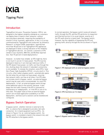
JOINT ASSEMBLY PARTSThe Four Easy Steps to Joint AssemblyFor all Selkirk Metalbestos pipe and fittings,the flange-to-flange inner pipe joints areidentical for each pipe inside diameter.Temperature of gases carried in the systemdetermines the proper sealant used.*As shown in the adjoining illustration andphotos, assembly is accomplished in four easysteps, using only standard tools.*See Grease Duct, Boiler Stack, or Engine Exhaust instructions for correct sealant usage.6Step 1Step 2Fill Inner Vee Band (VB) withproper sealant.Position Inner VB below flangeof pipe or fitting.Step 3Step 4Mate flanges of two pipes.Position Inner VB over bothflanges and tighten.Position Outer Channel Bandaround outer casing. Align withpipe grooves and tighten.
DOUBLE WALL PIPEADJUSTABLE/VARIABLE PIPEStraight Pipe LengthsAdjustable Pipe LengthsCodes: 60, 42, 30, 18Codes: AG30, AG18Standard pipe lengths for all SelkirkMetalbestos exhaust systems.Fills odd dimensions and compensates for expansion betweentwo fixed points on low pressureapplications.*Materials Available (shaded areas):304/Alum316/Alum304/304316/31660" lengths available in aluminized outers only. 60" lengths available in 8" dia. through 14" dia., all products. 42" lengths available in: 6" dia. through 32" dia., PS and lPSC1 6" dia. through 28" dia., IPSC2 6" dia. through 24" dia., IPSC4 18" & 30" lengths available in all diameters (5"-48") of all products(PS, IPSC1, IPSC2, and IPSC4).Ordered Part Includes:*Materials Available (shaded areas):304/Alum316/Alum304/304316/316Pipe, plus one VB and one CB.Ordered Part Includes:Notes:1. Special pipe lengths from 5" to 60" available upon request.Pipe, plus one 30" or 18" inner Slip Section, one TSU, one PackingSeal, one two-piece Compression Band, one two-piece ContainmentRing, one two-piece Outer Jacket, and one VB.2. K Factors (Where L pipe length in feet and D pipe diameter in inches)a. For Boiler Stacks and Chimneys:LK 0.30Db. For Diesel and Turbine Exhausts and Grease Ducts:LK 0.25De.g. for 50 feet of 10 inch diameter pipe50 1.25K 0.2510Fiber insulation provided for IPS models.Notes:1. Minimum installed length is 4".2. AG 18 not available for 28" diameter and above.3. Maximum installed space is when the inner slip section protrudes atleast 1/2 pipe diameter into the adjacent pipe.4. Flow Resistance Factor (K) is the same as insulated pipe lengths.7
DOUBLE WALL FITTINGSLined Bellows JointVariable Pipe Lengths90 Manifold TeeCode: BJCodes: VL30, VL18Code: MTProvides a pressure tightexpansion joint forengine exhaust andother high pressureapplications.Fills odd dimensionsbetween standardlengths. (Not usedto compensate forthermalexpansion.)Joins vertical andhorizontal sections toaffect a changeof direction.Also providesfor connectionof drain orinspection fittings. VL30 fills4"-- 26" space. VL18 fills4"-14" space.Dimension APS/IPSC1 IPSC2 IPSC44"5"7"Materials Available (shaded areas):304/Alum316/Alum304/304316/316Materials Available (shaded areas):Materials Available (shaded areas):Ordered Part Includes:304/AlumBJ, plus one Liner, one Outer Jacket (IPSonly), and one VB.Ordered Part Includes:Ordered Part Includes:VL30 or VL18, plus one 30" or 18" Inner SlipSection, one two-piece Outer Jacket, one SR,and one VB.MT, plus one VB for the body diameter, oneVB for the snout diameter, and one CB for thebody diameter.Fiber insulation provided for IPS models.Notes:1. Use TCN for clean out or inspection, or TCfor drain at base of vertical stack.Fiber insulation provided for IPS models.Notes:1. Optional to standard adjustable pipelengths.2. Liner protects Bellows but limits movementto liner expansions only.3. Flow Resistance Factor (K) is the same asinsulated pipe.4. Part is not available above 24" diameter.8316/Alum304/304316/316Notes:1. The SR is sealed with supplied sealant, notallowing the VL to compensate forexpansion.2. Flow Resistance Factor (K) is the same asinsulated pipe.304/Alum316/Alum304/304316/3162. Snout available in any standard diameterequal to or smaller than the body diameter.3. K 1.25 Flow Resistance Factor
DOUBLE WALL FITTINGS90 Grease Duct Tee45 Lateral TeeCode: GMTCode:Part MT with dam added for protection against fluids running outwhile cleaning.Provides a low resistance entry intomanifolds. Combine with EL45 for lowresistance 90 direction change.Materials Available (shaded areas):304/AlumOrdered PartIncludes:Dimension APS/IPSC1 IPSC2 IPSC44"5"7"Materials Available (shaded areas):304/Alum316/Alum304/304Ordered Part Includes:GMT, plus one TCN, two VB's and one CB.Notes:1. K 1.25 Flow Resistance Factor316/Alum316/316JL, plus one VB forthe body diameter,one VB for the snoutdiameter, and one CBfor the bodydiameter.Notes:1. Snout available inany standarddiameter equal toor smaller thanthe body diameter.2. K 0.4 FlowResistance Factor304/304Product316/316Dimensions(O. D.)(pipe I. D.)7PS IPSC2 IPSC4IPSC15––(inches)A191 2B133 4C53 48/965–191 2133 453 41086–22 8516 861 412108–24 161951 1614121062615 16217 1651 21614128293 4237 857 818161410329 16261 465 1620181612353 8283 463 42220181438 1631 1671 82422201643 835 8826242218437 8357 8828262420499 16403 4813 1630282622499 16403 4813 163230282455 1645 1695 83432302655 1645 1695 836–322860 1650 8107 163836–3060 1650 8107 1640–36326915 16581 4113 44442–366915 16581 4113 446–42–793 16661 8135048–42793 16661 81352–48–88 874 4147 1656––4888 874 4147 16713733131355179933119
DOUBLE WALL FITTINGS90 WYEDrain Tee CapCode: JYCode: TCProvides low pressuredrop for joiningappliances in thehorizontal and verticalposition.Provides a drain at thebase of a verticalchimney when connectedto the MT or JL.Materials Available (shaded areas):304/Alum316/AlumOrdered PartIncludes:JY, plus two VB's and one CB.304/304316/316ProductDimensions(O. D.)(pipe I. D.)7PS IPSC2 IPSC4IPSC15––(inches)A45 8B9Notes:1. All openings are the samediameter.8/965–4 891086–51 161012108–511141210651 2122. Can be used with TCN toprovide a single clean outtoward each 90 directionchange.161412857 8131816141063 8142018161265 8152220182422203. Use OT or OS as neededfor smaller branchconnections.262422188192826242083 4223028262283 4223230282495 8244. K 0.6 Flow ResistanceFactor3432302695 82436–3228101 2273836–30101 22740–3632113 4314442–36113 43146–42–13345048–42133452–48–14 43856––48141 4381051417 817168191Materials Available (shaded areas):304/Alum316/Alum304/304316/316Ordered Part Includes:TC, plus one 1" N.P.T. Nipple (5"-20" sizes), or 2" N.P.T. Nipple(22"-48" sizes), one Inner Section, one Outer Jacket, and one VB.Fiber insulation provided for IPS models.
DOUBLE WALL FITTINGSCleanout Tee Cap15 ElbowCode: TCNCode: EL 15Provides for cleanout atend of manifold whenconnected to MT or JL.Two-piece Elbow canestablish many differentdegrees when combined withother standard Elbows.Materials Available (shaded areas):304/Alum316/AlumOrdered Part Includes:Two 7 1/2 Elbows, plus two CB's,and two VB's.Notes:1. K 0.06 Flow Resistance FactorMaterials Available (shaded areas):304/Alum316/Alum304/304316/316Ordered Part Includes:TCN, plus one Inner Section (with handle), one Outer Jacket (withhandle), and one VB.Fiber insulation provided for IPS models.304/304316/316ProductDim.(O. D.)(pipe I. D.)(inches)7PS IPSC2 IPSC4IPSC15––A43 168/965–108612108–45 16141210677 16161412841 21816141049 162018161245 822201814411 162422201643 426242218413 162826242047 830282622415 163230282453432302651 1636–322851 838363053 1643 1641 440–363255 164442–3653 846–42–51 25048–4259 1652–48–59 1656––4859 1611
DOUBLE WALL FITTINGS30 Elbow45 ElbowCode: EL30Code: EL45Used for a vertical or horizontaldirection change of 30 .Used for a vertical or horizontaldirection change of 45 .Materials Available (shaded areas):304/AlumOrdered PartIncludes:EL 30, plus one CBand one VB.Notes:1. K 0.12 FlowResistance Factor12316/AlumMaterials Available (shaded areas):304/304Product316/316Ordered PartIncludes:Dimensions(O. D.)(pipe I. D.)7PS IPSC2 IPSC4IPSC15––304/Alum(inches)A61 8B61 8C223 88/965–61 861 8227 81086–36 836 823 812108–611 16611 16247 8141210675 1675 16271 4161412877 877 8295 81816141081 481 42018161285 885 8222018141242220262428EL45, plus One CBand one VB.316/Alum304/304Product316/316Dimensions(O. D.)(pipe I. D.)7PS IPSC2 IPSC4IPSC15––(inches)A81 2B12C298/965–81 212291086–815 16125 8307 812108–95 16133 16317 81412106101 4141 23516141281011 16143 8355 8305 818161410115 8167 16395 8315 820181612121 16171 16411 89 819 8134 8222018141318 8441 41639 839 8352422201613 1618 16451 2221810 1610 1637 22624221814 1620 4481 826242010 1610 1638 22826242014 821 16507 830282622111140 83028262215 1622 16531 23230282411 411 441 83230282416 422 16533 83432302611 811 844 83432302617245836–3228123 16123 16453 836–3228179 16243 4597 83836–30127 8123 4473 43836–30183 82515 16625 840–3632131 8131 8487 840–3632187 82611 16641 24442–361414521 24442–361911 16277 86746–42–141 4141 4531 846–42–201 8287 16685 85048–42143 16143 16567 165048–42217 16305 16747 852–48–15 1615 1657 852–48–21 1630 16747 856––4815 1615 1657 856––4821 1630 16747 815175515175571177311Notes:1. K 0.15 FlowResistance Factor557111773131131555
DOUBLE WALL FITTINGS90 ElbowTapered Increaser/ReducerCode: EL90Code: OTUsed for a vertical orhorizontal direction changeof 90 .Used when a pipediameter change isrequired.Materials Available (shaded areas):304/Alum316/Alum304/304Materials Available (shaded areas):Ordered Part Includes:EL90, plus one CB and one VB.Notes:1. K 0.30 Flow Resistance Factor316/316ProductDim.304/Alum316/Alum(O. D.)(pipe I. D.)(inches)7PS IPSC2 IPSC4IPSC15––A101 2Dimensions:A Smaller Diameter8/965–11 21086–121 212108–131 21412106141 21614128151 218161410161 220181612171 22220181418 224222016191 226242218201 228262420211 230282622221 23230282423 234323026241 236111322825 236–30261 240–3632271 24442–36291 246–42–301 25048–42321 252–48–331 256––48351 2381304/304316/316B Larger DiameterC Installed Length [(B-A) 2] 2 (see Note 1 below)Example:Installed Length for 12P304-180T equals [(1 8-12)2] 2 14".Ordered Part Includes:OT, plus one two-piece Outer Jacket, and one VB for smaller diameter.Fiber insulation provided for IPS models.Notes:1. Installed length shall not be greater than longest available straightpipe length (see page 6) for each diameter.2. K N [1 -(A/B)2]2where N 0.47 for one step OTN 0.53 for two step OT13
DOUBLE WALL FITTINGSStep Increaser/ReducerDrain SectionCode: 0SCode: DSUsed when pipe diameter changeis required in a small space.Used with open stack terminationsfor draining off rain waterfrom inside vertical orhorizontal flue.Materials Available (shaded areas):304/AlumMaterials Available (shaded areas):304/Alum316/Alum304/304316/316Ordered Part Includes:OS (Inner Stepped Pipe), plus one two-piece Outer Jacket, and one VBfor the smaller diameter.Fiber insulation provided for IPS models.Notes:1. This is a non-structural part; use only if OT will not fit within theallowable space.2. K N [1 -(A/B)2]214316/Alum304/304316/316Ordered Part Includes:DS, plus one Drain Dam within the pipe length, one 1" Nipple, oneCB, and one VB.Notes:1. K 0.25 Flow Resistance Factor
SUPPORT/GUIDE ACCESSORIESAngle RingsPlate Support AssemblyCodes: HR & FRCode: PAUsed for guiding and/or supporting horizontalinstallations.Half Ring (HR)Used for supportingthe load ofthe stack,and as afixed pointanchornearfittings.Wall SupportAssemblyCode: WA"Limited" support assembly with factorysupplied bracing.Full Ring (FR)Materials Available:Electroplated or Galvanized SteelNotes:1. Model PS part used for IPSC1 applications.ProductDimensions (inches) - HR(pipe I. D.)PSBoltHoleIPSC2 IPSC4 Circle5–6–I.D.ofRingNo of Size AngleHolesofof(HR) Angles Holes971 86(1)4551081 86(1)458612101 86(1)4510814121 86(1)45121061614 86(1)451412818161 86(1)4516141020181 86(1)45118161222201 86(1)4520181424221 86(1)4522201626241 810(2)22.524221828261 810(2)22.52624203028 810(2)22.528262232301 810(2)22.530282434321 810(2)22.532302636341 810(2)22.5–322838361 810(2)22.536–3040381 810(2)22.5–363242401 810(2)22.542–3646441 810(2)22.5–42–48461 810(2)22.548–4252501 810(2)22.5–48–54621 810(2)22.5––4858661 810(2)22.51(1) Size of Angles 1 2 x 1 2 x 1611(2) Size of Angles 2 x 2 x 3 163Materials Available:Electroplated or Galvanized SteelMaterials Available:Ordered Part Includes:Split (square) plate, one CF, two HCB's andhardware.Plate Thickness:0.188" for sizes 6" through 20" diameters0.250" for sizes 22" through 36" diameters0.375" for sizes 42" through 48" diametersNotes:1. Two 316 Stainless Steel HCB's should beordered separately for stainless steel outerprojects.Electroplated or Galvanized SteelOrdered Part Includes:One FR, two CF's, two HCB's, five brackets,two struts, and all hardware exceptconnection at wall.Notes:1. Assembly will maintain a 4" clearancebetween pipe O.D. and supportingstructure.2. PA fabricated from 304 Stainless Steel isavailable upon request and is nonreturnable. Allow extra manufacturing time.15
CONNECTION ACCESSORIESWall Guide AssemblyFloor Guide AssemblyFlanged Boiler KitCode: WGCode: FGCode: BKSame use as FIR, but with factory-suppliedbracing.Same use as FR, but with factory-suppliedbracing for use at floorlevel.Materials Available:Electroplated or Galvanized SteelOne FR, two struts, and two straps.Electroplated or Galvanized SteelNotes:1. Maximum hole through floor should notexceed the pipe O.D. plus 8".2. Model PS part used for IPSC1 applications.Pipe I.D. (inches)Ordered Part Includes:One FR, four struts, and six brackets.Notes:1. Assembly will maintain a 4" to 10"clearance between pipe O.D. andsupporting structure.2. Model PS part used for IPSC1 �5–68101214161820222426283032–3642––48171 218191 221221 2242729303233341 2363738391 241421 24446485052535458(1) Steel Angle, 11 2" x 11 2" x 3 16"(2) Steel Angle, 13 4" x 13 4" x 3 16"(3) Steel Angle, 2" x 2" x 3 16"16Material (inches)StrutLengthMaterials Available:Electroplated or Galvanized SteelOrdered Part Includes:Materials Available:Used for connecting piping to an appliancehaving a flanged d Part Includes:Two overlapping rings, hardware and required"C" type clamps (see table below).Notes:1. Model PS part used for all IPS applications.Pipe s)11 211 211 211 211 211 211 211 211 211 211 211 211 211 211 211 211 211 2I.D.(inches)53 1663 1683 16103 16123 16143 16163 16183 16203 16223 16243 16263 16283 16303 16323 16363 16423 16483 16
CONNECTION ACCESSORIESSeal RingFlange AdapterClamp FlangeCode: SRCode: FDCode: CFUsed for non-welded attachment to applianceshaving an unflanged or collar outlet.Provides a rigidconnection to a125 lb. or 150 lbANSI flange.Can be used as an attachment to flangedequipment (also part of PA and WA).A Flange I.D.PS/IPSC1 I.D. 5"C2 I.D. 7"C4 I.D. 11"B Bolt Hole CirclePS/IPSC1 I.D. 4"C2 I.D. 6"C4 I.D. 10"Materials Available (shaded areas):Materials Available (shaded lum304/304C Flange I.D.316/316Ordered Part Includes:Ordered Part Includes:Flange welded to TS, one CB, and one VB.SR, plus one VB and hardware.Fiber insulation provided for IPS models.Notes:1. Model PS part used for all IPS applications.ProductDimensions (inches)BoltFlangeHole Dia.O.D.7 810I.D.5No. ofBolts868788710121212141216PipeBoltCircle81 2 81191 2 8131 2113 4116141 41191711 821183 41611 8231 2211 4181611 425223 4202011 427 225222031 8129 227 4242013 832291 2282831 836 234302831 838 236322815 8413 4381 2363215 846423 4423615 853491 2484415 8591 256111PS/IPSC1 I.D. 1/2"1C2, C4 Materials Available:Electroplated or Galvanized SteelOrdered Part Includes:Two half clamp flange plates.Notes:1. 0. 139" minimum thickness for sizes 5" to8" diameters.2. 0.188" minimum thickness for sizes 10"through 36" diameters.3. 0.375" minimum thickness for sizes 42"and 48" diameters.4. Model PS part used for IPSC1 applications.17
CONNECTION ACCESSORIESFlanged HoodTransitionUnflanged HoodTransitionFanAdapterCode: TSCode: TSUCode: FAUsed on standard appliances such as kitchenhood exhausts. Flanged at both ends.Used on standard appliances such as kitchenhood exhausts. Flanged at one end.Used for connection to an "up-blast" kitchenexhaust fan.Materials Available (shaded areas):Materials Available (shaded areas):Materials Available (shaded ered Part Includes:Ordered Part Includes:Ordered Part Includes:TS, plus one CB and one VB.TSU, plus one CB and one VB.FA, plus one VB and one CB.Fiber insulation provided with IPS models.Fiber insulation provided with IPS models.Notes:1. Can be used for welding to equipment ortransitions fabricated in the field.Notes:1. Can be used for welding to equipment ortransitions fabricated in the field.Notes:1. Dimension of square plate (which issandwiched between curb and fan housing)must be specified when ordering.18
ROOF PENETRATIONSStorm CollarTall FlashingPitched Tall FlashingCode: SCCode: TFCode: PTFUsed above the TF and PTF for completeweatherization above the roof.Used in conjunction with SC forweatherization at the roof.Same function as TF, except for use on apitched roof.Materials Available (shaded areas):Materials Available (shaded areas):Materials Available (shaded areas):Aluminized or Galvanized Steel304316Aluminized or Galvanized Steel304316Aluminized or Galvanized Steel304316Ordered Part Includes:Ordered Part Includes:Ordered Part Includes:SC, plus hardware.TF only.PTF only (specify pitch when ordering).Notes:1. R
Building Heating Appliance Chimney (Industrial) 1400 F Chimney Type L Vent (Model IPS only) (Canada) Grease Duct 540 C (1000 F) Industrial Chimney 760 C (1400 F) Industrial Chimney UL file numbers for PS and IPS include MH6673 and MH11382 APPLICABLE MODELPS/IPS REFERENCES Building Heating Appliance Chimney UL103 NFPA211 NFPA31 NFPA37 ULC-S604