Transcription
COP-0005-PR-ZGeneral Workmanship Standards for Fabricated MaterialsRevision CNumber:Title:Type:Owner:Approval Table:COP-0005-PR-ZGeneral Workmanship Standards(Fabricated Materials and Electronic and Electromechanical Parts)Corporate Operating ProcedureMechanical EngineeringNote: Electronic approvals (names and dates) are recorded electronically in IFS.Initiated By:Signature on FileRey Taningco, Quality System Manager, SnoqualmieReviewed By:Signature on FileEmmett Anderson, Director of Supply ChainReviewed By:Signature on FileStéphane Pelletier, QA Manager, QuebecReviewed By:Signature on FileEvans Nguyen, Engineering ManagerReviewed By:Signature on FileBenoit Cliche, Mechanical Engineering Manager, QuebecReviewed By:Signature on FileFrédéric Morrow, Engineering Manager, QuebecReviewed By:Signature on FileAndy Martin, Systems Delivery Manager, SnoqualmieReviewed By:Signature on FileKaren Bernardi, Director, Probes, SnoqualmieApproved By:Signature on FileTom O’Dell, Director of EngineeringRelease Authority:Signature on FileRey Taningco, Quality System Manager, SnoqualmieRelease Concurrence:Signature on FileBill Thomson, VP OperationsThis Document Expires 5 Years from Approved By DateThis document contains proprietary information and is considered confidential Zetec intellectual property.Page 1 of 22
COP-0005-PR-ZGeneral Workmanship Standards for Fabricated MaterialsRevision CRevision d format to be consistent with COP-0008-FA-Z.Updated figure labels. Updated internal corner spec (8.4).Added 1.3. Added PCBA revision to 13.18.3.Issued ByR. TaningcoUpdated references to ANSI/ASME Y-14.5 and ENG-3002-PR-S.(Section 1.6). Added cosmetic criteria for seamless tubing(10.4). Modified radius limit for internal corners (5.4).B20-Feb-2018Added electrical sections that were originally in document 011005 (section 10).R. TaningcoAdded PMUC requirements (section 14).Updated with Systems and Quebec correctionsAdded Critical Dimensions instructionsA11-Aug-2015Initial releaseD. WesterlingTABLE OF CONTENTS1.PURPOSE AND SCOPE . 32.DEFINITIONS AND ACRONYMS . 33.REFERENCES AND GOVERNING DOCUMENTS. 34.RESPONSIBILITIES . 45.ORDER OF PRECEDENCE . 56.QUALITY ASSURANCE REQUIREMENTS . 57.DRAWINGS . 58.MACHINED PARTS . 79.SHEET METAL PARTS . 910.WELDING . 1011.CASTINGS . 1112.FINISH/PLATING . 1213.ELECTRONIC AND ELECTROMECHANICAL PARTS . 1314.COSMETIC STANDARDS AND SPECIFICATION . 1715.CLEANING . 2116.PACKING . 2217.PMUC-COMPLIANT MATERIALS. 2218.ROHS COMPLIANCE . 2219.RECORDS AND DOCUMENTATION - NONE . 2220.EXCEPTIONS AND SPECIAL CIRCUMSTANCES - NONE. 22This document contains proprietary information and is considered confidential Zetec intellectual property.Page 2 of 22
COP-0005-PR-ZGeneral Workmanship Standards for Fabricated MaterialsRevision C1. PURPOSE AND SCOPE1.1.This document establishes a minimum standard for workmanship required of allfabricated materials produced within or outside of Zetec Inc., necessary for theproduction of the organizations products. The intent is to mitigate quality variations andmaintain uniformity among materials fabricated globally.1.2.This document may be released to suppliers of mechanical, electronic andelectromechanical parts (PCBAs, probes, motors, etc.) that are made following Zetec’sdesign requirements. This document may not be released to suppliers of off-the-shelfparts.1.3.This document replaces document 01-1005.2. DEFINITIONS AND .2.9.2.10.2.11.2.12.Industry US Customary Units2.14.2.15.2.16.STDGTAWGMAWKnowledge and skill at performing a task that imparts qualityto a productGenerally accepted requirements followed by the NDT industryNon-Destructive TestingAmerican National Standards InstituteAmerican Society of Mechanical EngineersAmerican Society for Testing and MaterialsAssemblyBill of MaterialsComputer Aided DesignGeometric Dimensioning and TolerancingInternational System of UnitsProduits et Matériaux Utilisables en Centrale (Products andMaterials used in Power Plants)Units of measure commonly used by manufacturers in theU.S.A. i.e. inches, mills, etc.StandardGas Tungsten Arc WeldingGas Metal Arc Welding3. REFERENCES AND GOVERNING DOCUMENTSThe following documents are utilized as the basis for this guideline. Equivalent guidelines, used inthe country of part manufacturing origin, are also acceptable.3.1.Federal3.1.1.A-A-56032Ink marking, Epoxy Base3.1.2.FED-STD-H2Screw-Thread Standards for Federal Services3.2.Military3.2.1.MIL-HDBK-60Threaded Fasteners Tightening to ProperTensionThis document contains proprietary information and is considered confidential Zetec intellectual property.Page 3 of 22
COP-0005-PR-ZGeneral Workmanship Standards for Fabricated MaterialsRevision C3.2.2.3.2.3.3.3.3.4.MIL-STD-100GMIL-STD-12DoD Standard Practice for Engineering DrawingsAbbreviations for use on Drawings,Specifications, Standards and in Technicaldocuments3.2.4.MIL-STD-889Dissimilar MetalsAmerican Industry Standards ANSI/ASME/ASTM3.3.1.ANSI B4.2Preferred Metric Limits and Fits3.3.2.ASME B46.1Surface Texture, Surface Roughness, Wavinessand Lay3.3.3.ANSI/ASME Y-14.5Dimensioning & Tolerancing Standard3.3.4.ASME B1.13M-2005Metric Screw Threads, M Profile3.3.5.ANSI/ASME B94.6Knurls and Knurling3.3.6.ASTM-A 997Investment Casting, Surface Acceptance, VisualExamination3.3.7.ANSI/AWS A2.4Weld Symbols3.3.8.AWS WHB-1.9Welding Handbook3.3.9.AWS WI 2000Welding Inspection Handbook3.3.10. ANSI/AWS C5.5/C5.5M 2003 Gas Tungsten Arc Welding3.3.11. ANSI/AWS D9.1M/D9.1 2006 Sheet Metal WeldingZetec Inc.3.4.1.ENG-3002-PR-SEngineering Drawing Practices3.4.2.10001403Fastener Captivation Torque Index3.4.3.10021176Knurling Spec Jig, Heavy3.4.4.PRO-3105-WI-SESD Handling3.4.5.IPC-A-600 Class 2Acceptability of Printed Boards3.4.6.IPC-A-610 Class 2Acceptability of Electronic Assemblies3.4.7.IPC/WHMA-A-620 Class 1(Unless otherwise specified by drawing and/orPurchase Order), Requirements and Acceptancefor Cable and Wire Harness Assemblies3.4.8.QAP-015S-2015-PR-SCalibration Standard Fabrication andCertification3.4.9.SCM-3812-FA-SSupplier Codes for Serialized PCBAs3.4.10. 1004479Probe Trademark Label Specification.4. RESPONSIBILITIES4.1.The Zetec Engineering Department owns this document and is responsible for changesherein. Should a fabrication drawing reference this document, it is the responsibility ofZetec internal manufacturing, and or external contractors producing Zetec components,to abide by the standards herein.This document contains proprietary information and is considered confidential Zetec intellectual property.Page 4 of 22
COP-0005-PR-ZGeneral Workmanship Standards for Fabricated MaterialsRevision C5. ORDER OF PRECEDENCE5.1.The following documents take precedence in the order listed in event of interpretationconflicts. In all cases, the applicable document refers to the latest revision.5.2. Zetec Inc. Engineering drawings and design documents. Zetec Inc. Manufacturing and production documents. Zetec Inc. General Drafting and Design Guidelines. Industry Standards.UnitsThe S.I. system is the primary unit of measure referred to in this document. Alternatively,US Customary Units may be expressed in the drawings.6. QUALITY ASSURANCE REQUIREMENTS6.1.Zetec Quality SystemThe quality system at Zetec is consistent with ISO Standard 9001.2008 and is described inZetec Quality documentation.6.2.Supplier Quality SystemThe Quality System of Qualified Suppliers will be evaluated against the applicableelements of the appropriate ISO Standard 9001.2008 and the specific requirements ofthe materials, component, and assemblies involved. Suppliers are qualified in accordancewith applicable Materials and Procurement Procedures.6.2.1.First ArticleSupplier Q/A results are to be submitted with first article built to print parts.This requirement continues pending a certification review by Zetec Q/A,followed by supplier notification. Notify Zetec before making additional parts ifno confirmation has been received.7. DRAWINGS7.1.Drawing InterpretationInterpretation of dimensions and tolerance requirements shall be in accordance withANSI/ASME Y- 14.5, and clarified within this document. Unless otherwise specified bydrawing and/or Purchase Order, all dimensions are finished dimensions which apply afterthe part has been heat treated, plated, anodized etc. If not specified on the drawing themanufacturer of the component shall achieve this condition in any way necessary toproduce the part, including, but not limited to the following method: Masking Post-op machining Accommodating the plating buildup in the initial machining stepThis document contains proprietary information and is considered confidential Zetec intellectual property.Page 5 of 22
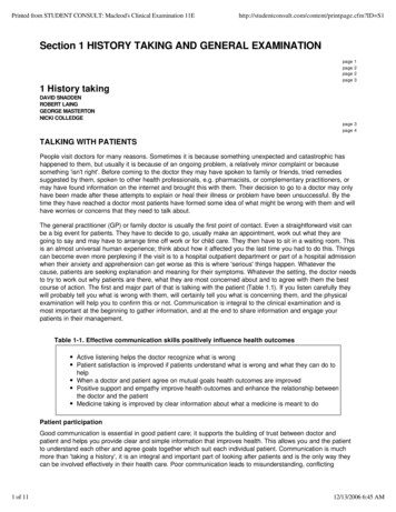
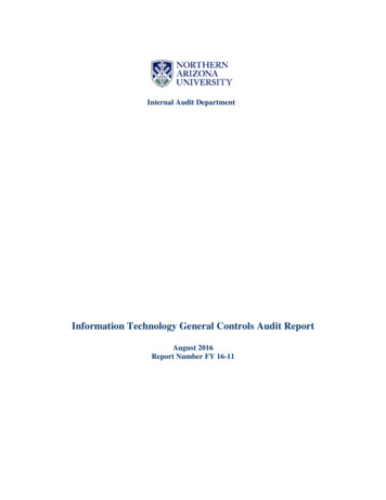
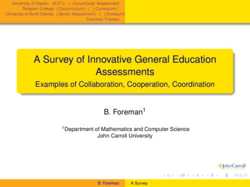
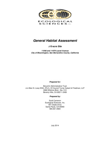
COP-0005-PR-ZGeneral Workmanship Standards for Fabricated MaterialsRevision C7.2.7.3.Right AnglesRight angle features depicted on the drawing that are not dimensioned, such as squarefaces, centerlines, holes, etc. shall be interpreted as a 90 angle with tolerance specifiedin the drawing title block.Unassigned DatumWhen features such as diameters are shown on a common axis, but dimensionedwithout apparent base line or datum, the feature to select as the datum shall be thatwhich provides the worst case tolerance stacking analysis. For example, the datumselected in Figure 1 shall be either feature A1 or A3. When in doubt, contact Zetec forclarification.Figure 1, Unassigned Datum7.4.7.5.7.6.7.7.Bolt Circle SpacingWhere the term “equally spaced” is used to define the location of holes or features onbolt circles (B.C.) and similar patterns, the angular tolerance for each hole shall be thatspecified within the drawing title block.Implied symmetryFeatures that are drawn around the centerline of another feature do not requiredimensional location; symmetry is implied about the centerline and block tolerancesapply.Inspection DimensionsAll drawings shall conform, and be interpreted, to the dimensioning and tolerancingrequirements of Inspection Dimension. Dimensions enclosed with a bubble, denotea critical dimension per the ENG-3002-PR-S. In addition, any metric dimensions less than0.1mm (or dimensioned to the 0.0X place) and Standard dimensions less than 0.01 (ordimensioned to the 0.00X place) will be considered critical dimensions by QC and notrequire any special call outs. The inspection plan for the critical dimensions will bedetermined by QC as well as governing documents.Un-Dimensioned Features7.7.1.Drawings that are not fully dimensioned shall be controlled by the 3D model.The following note shall apply. When in doubt, contact Zetec for clarification.This document contains proprietary information and is considered confidential Zetec intellectual property.Page 6 of 22
COP-0005-PR-ZGeneral Workmanship Standards for Fabricated MaterialsRevision C7.8.All features not directly dimensioned are controlled by the 3d model as shown below.7.8.1.7.8.2.Drawings shall have, at minimum, the following features dimensioned in theprint: All tapped holes All precision holes All critical to function features All features with tolerance requirements tighter than the title blocktolerances Overall dimensions (may be reference) to aid estimates and quotesAssumptions that can be made by manufactures for un-dimensioned features: Internal pocket radii are considered MAX Block tolerances apply to features not governed by the profile tolerance Machining lay is uncontrolled8. MACHINED PARTS8.1.LubricantsMachining lubricants and cutting fluids should be aqueous base and of low or no sulfur orchlorine chemistry.8.2.BurrsAll parts shall be free of sharp projections (burrs) created by the fabrication process,applicable to all features of a part.8.3.External CornersUnless otherwise specified by drawing and/or Purchase Order, all external corners andedges shall have a break, defined as removal of material from the corner or edge so as tocreate a minimum 0.1mm to maximum 0.18 mm or 0.004” to
15.03.2019 · ANSI/ASME Y- 14.5, and clarified within this document. Unless otherwise specified by drawing and/or Purchase Order, all dimensions are finished dimensions which apply after the part has been heat treated, plated, anodized etc. If not specified on the drawing the manufacturer of the component shall achieve this condition in any way necessary to produce the part, including, but not