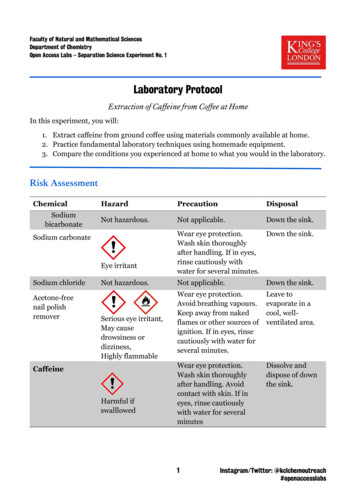
Transcription
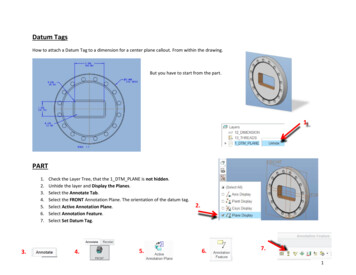
Datum TagsHow to attach a Datum Tag to a dimension for a center plane callout. From within the drawing.But you have to start from the part.PART1.2.3.4.5.6.7.3.Check the Layer Tree, that the 1 DTM PLANE is not hidden.Unhide the layer and Display the Planes.Select the Annotate Tab.Select the FRONT Annotation Plane. The orientation of the datum tag.Select Active Annotation Plane.Select Annotation Feature.Select Set Datum Tag.4.5.2.6.7.1
Enter the Datum Tag letter C.Toggle on Reference Datum.Toggle on Placement On Datum.Select the Datum Plane on the part,or from the Detail Tree.12. OK13. OK14. Save frequently and often.8.9.10.11.11.9.10.Note: In this example the datum tag goes on the datum plane, to indicatethe center datum plane. All other datum tags must be on the part surface.2
DRAWING1. Go to the Drawing.2. Select the Annotate tab.3. Erase the Datum tag in the views you do not want it displayed.4.5.6.7.Select the Datum tag from the displayed datum plane, Right Mouse Button select Properties.Select In Dim Pick DimPick the dimension for the Center Plane.Flip Witness Line if necessary.4.6.5.3
8. The Datum Tag triangle base lines up with the dimension arrow head.9. This means the datum plane C is at the mid-plane of the dimension.10. This is called Datum Plane C.11. A Datum Tag is NEVER place on a center line. Even though CREO allows this behavior to occur.Add tolerance.1. Add Plus .002 and Minus 0 tolerance.Add GD&T Position Feature Control Frame.1.1. Select the Annotate tab.2. Select the Geometric Tolerance.3. Select Position.4. Select the Datum C from the Model Tree.2.3.4.4
Datum Tags move1. After the GD&T Position is applied the Datum Tag moves to the Feature Control Frame.5
To many decimal places.Select the dimension RMB properties.Check Rounded Dimension Value to get metric dims to two decimal places.B4AFTER6
To change the orientation of the annotation.From the PART1.2.3.4.5.Right click on the dimension leader line.Select Pick From List.Select OK.Right click on the dimension leader line.Select Current Orientation.7
Things PTC never tell you, or I cannot find them.1. Cross sections can NOT be used to place datum tags. Select a feature view to place the GTOL or datum tag then RMB to getthe menu Move item to view.2. Check this setting in File Prepare Drawing Properties asme dtm on dia dim gtol on gtol or on dim.3. Do not add a datum tag to the primary datums. Create a new datum for the datum tags by selecting a surface or axis and letthat datum do that and only that. Their behavior for showing and not showing is a bit more predictable. I have found theparadox with always shown datums w/ tags in the model will flip when you show that datum in a drawing.4. If the model datums are hidden, any associated geotol will not show in the drawing, period.5. From what I've experienced, it may be best to create the geotols in the drawing once the datum tags are established in themodel.6. The take-away was that applying datum tags to primary datum planes makes them difficult to hide. However, if you createdatum tags on Geometry, Creo creates datum planes for that purpose behind the scenes and therefore, they can be hiddenmore easily. So create datum surfaces to make the tags more controllable.7. In the model. Add the datum axis tag to a separate layer.Then in the drawing.Right-click & select properties - Drawing Optionsset the option drawing layer overrides model to yesget the name of the view (e.g. TOP)View the layers in the model tree areaIn the drop-down box, select the viewSelect the layer with the datum axis & hide. Save layer status. Save drawing.8
8. Using standard iso/ansi settings, the datum flag will be placed on the diameter, and standard asme settings the flag will beplaced on the shoulder of the leader line facing up, or on the diameter, and if you have a control frame attached to thedimension in asme settings it will point downward off the center of control frame with a plunger, and if you use standard ansisettings there is no plunger extending from the control frame.9. After filing a tech support case I found that PTC actually intends is that the ANSI Y14.5M-1982 datum style button is used for2D drawing annotations and the ASME Y14.5M-1994 style button is used for 3D datum annotations. The layer issue with theASME Y14.5M-1994 style selection (3D annotations) is in debate whether it will be fixed in Creo 4.10. PTC please change the confusing symbology in the datum properties dialog box so that it differentiates between 2D and 3Dannotations without confusing users with ANSI and ASME standards.9
11. Currently, the datum properties dialog box shows 3 buttons: a regular datum, an ANSI Y14.5M-1982 datum and an ASMEY14.5M-1994 datum. Users frequently mistake these symbols to mean that if you select one of these buttons, the datum willconform to that standard. Unfortunately, the ASME Y14.5M-1994 style button creates an annotation that cannot be hiddenon a layer and frequently does not show up correctly in drawings.10
Datum Tags in the drawing1. Datum Tags do not always highlight when hovering over them with the cursor. Select the annotate tab, go ahead and Left Mouse Button,LMB, on the datum letter to select it. A small white square will appear, then hover the cursor over it and the datum tag will nowhighlight.2. Datum tags will NOT display on another sheet of multi sheet drawings if the datum tag is attached to a dimension or the feature controlframe, FCF, of a geometric tolerance.11
ASME Y14.5M-1994 style selection (3D annotations) is in debate whether it will be fixed in Creo 4. 10. PTC please change the confusing symbology in the datum properties dialog box so that it differentiates bet