Transcription
Document 483586Microprocessor Controller forDedicated Outdoor Air System Reference Guide for Microprocessor ControllerPlease read and save these instructions for future reference. Read carefully before attempting to assemble, install,operate or maintain the product described. Protect yourself and others by observing all safety information. Failureto comply with these instructions will result in voiding of the product warranty and may result in personal injuryand/or property damage.DOAS v3.001DOAS Technical SupportCall 1-866-478-2574IntroductionProgram FeaturesThe microprocessor controller offers control througheasy monitoring and adjustment of unit parameters byway of a lighted graphical display and an integral pushbutton keypad.Pre-Programmed Operating SequencesThe controller has been pre-programmed to offermultiple control sequences to provide tempered air.Factory default settings allow for easy setup andcommissioning. The sequence parameters are fullyadjustable. Refer to the Sequence of Operation fordetails.BMS CommunicationThe user can remotely adjust setpoints, view unit statuspoints and alarms. The microprocessor controller iscapable of communicating over several protocols: BACnet MSTP BACnet IP LonWorks Modbus RTU Modbus TCPReference Points List for a complete list of BMS points.Internal Time Clock (Schedule)The controller has an internal programmable time clock,allowing the user to set occupancy schedules for eachday of the week. The controller option also has morningwarm-up and cool down capability for improvedcomfort at the time of occupancy.Alarm ManagementThe microprocessor controller will monitor the unit’sstatus for alarm conditions. Upon detecting an alarm,the controller will record the alarm description, time, date, and input/output status points for user review. Adigital output is reserved for remote alarm indication.Alarms are also communicated via BMS (if equipped).Occupancy ModesThe microprocessor controller offers three modes ofdetermining occupancy: a digital input, the internal timeclock or the BMS. If in the unoccupied mode, the unitwill either be shut down, continue normal operationutilizing adjustable unoccupied setpoints, recirculatewith unoccupied setpoints or will cycle on to maintainadjustable unoccupied room temperature and humiditysetpoints (room temperature and humidity sensor isoptional).Remote Display Panel (if equipped)A touch pad display panel allows for remote monitoringand adjustment of parameters, allowing ease of controlaccess without going outdoors.WARNINGElectrical shock hazard. Can cause personal injury orequipment damage. Service must be performed onlyby personnel that are knowledgeable in the operationof the equipment being controlled.WARNINGMechanical high static protection cutoffs mustbe installed by others to protect the system andequipment from over-pressurization when usingfactory provided control sensors. The manufacturerdoes not assume responsibility for this.Microprocessor Controller for DOAS1
Table of ContentsSequence of OperationGeneral Operation . . . . . . . . . . . . . . . . 3-4Setpoint Control (Occupied) . . . . . . . . . . . . 4Setpoint Control (Unoccupied) . . . . . . . . . . . 4Heating . . . . . . . . . . . . . . . . . . . . . . . 4Cooling . . . . . . . . . . . . . . . . . . . . . . . 4Economizer . . . . . . . . . . . . . . . . . . . . . 5Dehumidification . . . . . . . . . . . . . . . . . . 5Reheat . . . . . . . . . . . . . . . . . . . . . . . 5Supply Fan VFD Sequence . . . . . . . . . . . . . 5Exhaust Fan VFD Sequence . . . . . . . . . . . . 5OA and Recirc Air Damper Control. . . . . . . . . 6Energy Recovery Wheel . . . . . . . . . . . . . . 6Alarms . . . . . . . . . . . . . . . . . . . . . . . 7Controller OverviewsLarge Controller . . . . . . . . . . . . . . . . . . 8Medium Controller . . . . . . . . . . . . . . . . . 9c.pCOe - Expansion Board Overview, Medium . . 10pCOe - 4:1 Furnace. . . . . . . . . . . . . . . . . 11pCOe - High Turndown Furnace . . . . . . . . . . 11Display Use . . . . . . . . . . . . . . . . . . . . . 12Example of Parameter Adjustment . . . . . . . . 12Example of Web User Interface . . . . . . . . . . 13Main Menu . . . . . . . . . . . . . . . . . . . . . 14Unit Status Overview. . . . . . . . . . . . . . 15-17Unit Enable . . . . . . . . . . . . . . . . . . . . . 18MenusControl VariablesTemp Control . . . . . . . . . . . . . . . . 18-20Dehumidification . . . . . . . . . . . . . . 20-21Refrigeration. . . . . . . . . . . . . . . . . . . 22Damper Control . . . . . . . . . . . . . . . 22-23Energy Recovery . . . . . . . . . . . . . . . . 24Fan ControlSupply Fans Control . . . . . . . . . . . . . 25Exhaust Fans Control. . . . . . . . . . . . . 26Occupancy . . . . . . . . . . . . . . . . . . . 27AdvancedManual Overrides . . . . . . . . . . . . . 28-30Network Settings . . . . . . . . . . . . . 30-31Backup/Restore . . . . . . . . . . . . . 32-33I/O Configuration . . . . . . . . . . . . . . . 34Unit Configuration . . . . . . . . . . . . . . 34Alarms . . . . . . . . . . . . . . . . . . . . . . 352Microprocessor Controller for DOASIG Furnace Alarm Descriptions . . . . . . . . . . 35AppendixRemote Display . . . . . . . . . . . . . . . . . . 36Carel NTC Temp Sensor Chart . . . . . . . . 36I/O Expansion Board Quick Start . . . . . . . . . 37Room Thermostat Quick Start. . . . . . . . . 38-39GreenTrol Airflow Monitoring Quick Start . . . . 40Points List . . . . . . . . . . . . . . . . . . . 41-52Modbus Connections . . . . . . . . . . . . . . . 53Maintenance Log . . . . . . . . . . . . . . . . 53-54Our Commitment . . . . . . . . . . . . . Backcover
Sequence of OperationThe microprocessor controller can be configured forair handler, energy recovery, and dedicated outdoor airsystems. Each application utilizes similar technologiesfor heating and cooling: chilled water, hot water, indirectgas, electric heat, packaged DX cooling, and packagedDX cooling with digital and inverter scrolls. All setpoints,lockouts and delays are user adjustable via the integralkeypad display, remote display, or web user interface.General OperationUNIT START COMMAND: The microprocessorcontroller requires a digital input to enable operation.The unit can then be commanded on or off by thisdigital input, keypad, the BMS or internal time clock.When a start command becomes active the followingsteps occur: Energy recovery wheel starts, if equipped Factory mounted and wired dampers are powered(Outdoor air, exhaust air, and recirculation airdampers, if equipped) Exhaust fan, if equipped, starts after adjustable delay Supply fan starts after adjustable delay Tempering operation starts after adjustable delayUNIT STOP COMMAND: A shutdown occurs whenthere is not an occupied or unoccupied start command.The following shutdown methods can occur.Hard shutdown occurs under the following conditions: A user or the BMS disables the system, and thesupply temperature is less than the soft shutdownenable setpoint. Occupancy is commanded to unoccupied while thereis no unoccupied start command, and the supplytemperature is less than the soft shutdown enablesetpoint.When a hard shutdown occurs: The unit shuts down immediately. Dampers spring-return to their off position.Soft shutdown occurs under the following conditions: A user or the BMS disables the system, and thesupply temperature is greater than or equal to thesoft shutdown enable setpoint. There is no unoccupied or occupied start commandand the supply temperature is greater than or equalto the soft shutdown enable setpoint.The following occurs during a soft shutdown: Tempering outputs immediately revert back to theiroff value; while Dampers remain open and fans continue to run; until– The supply air temperature falls below the softshutdown enable setpoint minus 5.0 F; or– The soft shutdown delay timer has expired. UNIT/SYSTEM DISABLED COMMAND:The unit becomes disabled due to the following: The unit was disabled from the controller’s UnitEnable screen. The unit was disabled from the BMS. The shutdown input is in the shutdown position. A shutdown alarm was activated.When disabled the following actions occur: The unit shuts down immediately; and Dampers spring-return to their off position.OCCUPIED/UNOCCUPIED MODES: Themicroprocessor controller offers three modes ofdetermining occupancy: digital input, the internal timeclock or the BMS. When in the unoccupied mode, theunit can be configured to shut down, or cycle on tomaintain the unoccupied room setpoints. The unit canbe temporarily overridden to the occupied mode viaa digital input, keypad display, or room thermostat, ifequipped.The controller can be configured with morning warmup and cool down to bring the space to the occupiedsetpoint prior to occupancy. Occupied Mode:- Exhaust fan on, if equipped- Supply fan on- Heating (refer to Heating section)- Cooling (refer to Cooling section)- Energy Recovery Wheel Control (refer toEnergy Recovery Wheel section), if equipped- Damper Control (refer to Outdoor Air andRecirculated Air section), if equipped Unoccupied Mode (Unit Off): Unit remains off whenin unoccupied mode. Normal Operation with Unoccupied Setpoints:Optional unoccupied mode will operate as if inoccupied mode but will utilize adjustable unoccupiedsetpoints.- Exhaust fan on, if equipped- Supply fan on- Heating (refer to Heating section)- Cooling (refer to Cooling section)- Energy Recovery Wheel Control (refer to EnergyRecovery Wheel section), if equipped- Damper Control (refer to Outdoor Air andRecirculated Air section), if equipped Recirculation with Unoccupied Setpoints: Optionalunoccupied mode when there is an unoccupiedrecirculation damper. The unit will continue to run,but in full recirculation.- Supply fan on- Recirculation air damper open- OA damper closed- Tempering operations beginMicroprocessor Controller for DOAS3
Sequence of Operation Unoccupied Mode (Cycle on Room): Optionalunoccupied mode when there is an unoccupiedrecirculation damper and room temperature and/or humidity sensor(s) connected to the controller.The unit will cycle on to maintain unoccupied roomsetpoints if there is a call for unoccupied heating,cooling or dehumidification.- Exhaust fan off, if equipped- Supply fan on- Recirculation air damper open- OA damper closed- Tempering operations beginSetpoint Control (Occupied)Supply air temperature setpoint can be configuredas constant, or can be reset by either outside airtemperature, or room temperature setpoint. If equippedwith BMS communications, the user can also directlycommand the supply temperature setpoint, or roomtemperature setpoint, if equipped. Outdoor Air Temperature Reset Function: Thecontroller will default to supply temperature resetbased on outdoor air temperature. The controller willmonitor the OA temperature and reset the supplytemperature setpoint based upon the outdoor airreset function. Room Temperature Reset (optional): With aroom temperature sensor, the controller will adjustthe supply air temperature setpoint betweenthe minimum (55 F) and maximum (90 F), tosatisfy the desired room temperature. Roomtemperature setpoint can be adjusted locally atthe microprocessor by BMS or room thermostat, ifequipped.Setpoint Control (Unoccupied)When equipped with an unoccupied recirculationdamper and optional room temperature and/orhumidity sensors, the unit will cycle on to maintain theunoccupied room setpoints. Unoccupied Heating: If equipped with heating,the unit is enabled when the room temperature isless than the unoccupied heating setpoint minusdifferential (60 F). The supply air temperature setpointwill be set to the supply maximum reset limit (90 F).The unit cycles off when the room temperaturereaches the unoccupied heating setpoint. Unoccupied Dehumidification: If equipped withcooling, the unit is enabled when the room relativehumidity exceeds the unoccupied room relativehumidity setpoint plus differential (50% 5%). Thesupply air temperature setpoint will be set to theequivalent occupied supply setpoint. Morning Warm-Up/Cool Down: The unit usesadjustable preset time to temper the space tooccupied setpoint prior to occupancy (roomtemperature sensor is optional).HeatingThe heating is controlled to maintain the supplytemperature setpoint. The heating will be locked outwhen the outside air temperature is above the heatinglockout (80 F adj). Indirect Gas Furnace: Microprocessor controllerwill modulate the indirect gas furnace to maintain thesupply temperature setpoint. Hot Water Coil: Microprocessor controller willmodulate a hot water valve (provided by others) tomaintain the supply temperature setpoint. Coil freezeprotection must be provided by others in the field! Electric Heater: Microprocessor controller willmodulate an electric heater to maintain the supplytemperature setpoint.CoolingThe cooling is controlled to maintain the supplytemperature setpoint. The mechanical cooling will belocked out when the outside air temperature is belowthe cooling lockout (55 F). Chilled Water: Microprocessor controller willmodulate a chilled water valve (provided by others) tomaintain supply air setpoint. Coil freeze protectionmust be provided by others in the field! Packaged/Split DX Cooling (Standard Scroll):Microprocessor controller will enable stages ofcooling to maintain the supply air setpoint. Packaged DX Cooling (Digital Scroll):Microprocessor controller will modulate the digitalscroll to maintain the supply air temperature setpoint. Packaged DX Cooling (Inverter Scroll):Microprocessor controller will modulate the inverterscroll to maintain the supply air temperature setpoint. Unoccupied Cooling: If equipped with cooling, theunit is enabled when the room temperature is greaterthan the unoccupied cooling setpoint plus differential(80 F 5 F). The supply air temperature setpoint willbe set to the supply minimum reset limit (55 F). Theunit cycles off when the room temperature reachesthe unoccupied cooling setpoint.4Microprocessor Controller for DOAS
Sequence of OperationEconomizerSupply Fan VFD SequenceIf the application requires cooling, and the outdoorair conditions are suitable for free cooling, thecontroller may enter the economizer state. If the unit iseconomizing and the discharge temperature setpoint isnot being met, the controller may bring on mechanicalcooling. If equipped with a modulating outdoor air andrecirculated air damper, the dampers will modulatebetween the minimum OA and maximum positions tomaintain the supply temperature setpoint. If equippedwith an energy wheel, Reference Energy RecoveryWheel Sequence.The factory installed VFD is wired to the controller.Supply fan speed needs to be set during testand balance of the unit. If equipped with BMScommunications, the user can also directly commandthe supply fan speed. Temperature: The economizer will be locked outwhen:- The outside air is greater than the economizerhigh lockout (65 F).- The unit is operating in dehumidification mode.- There is a call for heating. Temperature/Enthalpy: The economizer will belocked out when:- The outside air is greater than the economizerhigh lockout (65 F dry-bulb).- The outside air is greater than the economizerhigh enthalpy lockout (23 btu/lb).- The unit is operating in dehumidification mode.- There is a call for heating.DehumidificationThe cooling is controlled to maintain the cold coilsetpoint. The dehumidification sequence will be lockedout when the OA is less than the dehumidificationlockout (10 F) above the cold coil setpoint. If equippedwith BMS communications, the user can also directlyset the cold coil leaving air setpoint. Optional Room Relative Humidity Sensor orThermostat: The controller will adjust the coldcoil leaving air temperature setpoint between theminimum (50 F) and maximum (55 F) setpoint tosatisfy the desired room relative humidity setpoint.ReheatWhile the unit is in dehumidification mode, the supplyair can be reheated via Primary Heating Source, On/OffHot Gas Reheat or Modulating Hot Gas Reheat. Modulating Hot Gas Reheat (valve): Themicroprocessor controller will modulate the hot gasreheat valve to maintain the supply temperaturesetpoint. Reheat Plus: The primary heat source configured toact as secondary reheat. Optional Space/Duct CO2 Sensor: The controllerwill modulate the supply fan based upon acomparison of the CO2 setpoint to the actual CO2levels reported from the sensor. Optional Duct Static Pressure Sensor: Thecontroller will modulate the supply fan based upona comparison of the duct static pressure setpoint tothe actual duct static pressure level reported from thesensor. Optional Building Static Pressure Sensor: Thecontroller will modulate the supply fan based upon acomparison of the building static pressure setpoint tothe actual building static pressure level reported fromthe sensor. Optional Single Zone VAV (SZ): The controller willcontrol the supply air temperature and supply fanspeed to maintain the room temperature setpoint.This sequence requires a room temperature sensor.Heating - When the room requires heating,the controller will reset the supply air temperaturesetpoint up to the maximum (90 F) while increasingthe supply fan speed up to its maximum heatingspeed.Cooling - When the room requires cooling, thecontroller will first reset the supply air temperaturesetpoint down to the minimum (55 F) while thesupply fan remains at the minimum cooling speed.After a time delay, the supply fan speed will increaseup to its maximum cooling speed to maintain theroom temperature setpoint.Exhaust Fan VFD SequenceThe factory installed VFD is wired to the controller.Exhaust fan speed needs to be set during testand balance of the unit. If equipped with BMScommunications, the user can also directly commandthe exhaust fan speed. Optional Building Static Pressure Sensor: Thecontroller will modulate the exhaust fan based upon acomparison of the building static pressure setpoint tothe actual building static pressure level reported fromthe sensor. Optional Supply Fan Tracking: The controller willproportionally modulate the exhaust fan based uponthe supply fan speed. Optional Outdoor Air Damper Tracking: Thecontroller will proportionally modulate the exhaust fanbased upon the outdoor air damper position. Microprocessor Controller for DOAS5
Sequence of OperationOutdoor Air and Recirculated (Recirc) AirEnergy Recovery Wheel SequencesDamper ControlEconomizer (optional): If the unit is equipped with anIf equipped with a modulating outdoor air andrecirculated air damper, the recirculated air damper willoperate inverse of the outdoor air damper. The outdoorair damper will open to a Minimum Outdoor Air Position(Min OA) when in occupied mode. If the controlleris configured to modulate the supply fan speed, theminimum and maximum OA positions can be resetbased on supply fan speed. If equipped with BMScommunications, the user can also directly reset thedamper position up to the maximum OA position. Optional Space CO2 Sensor: The controller willproportionally modulate the OA/RA dampers basedupon a comparison of the CO2 setpoint to the actualCO2 level reported from the sensor. As the CO2 levelrises, the controller will proportionally modulate theoutdoor air damper open, between the minimum OAdamper position and maximum CO2 position. Optional Building Pressure: The OA/RA damperswill modulate based upon the signal from a buildingstatic pressure sensor. The controller will modulatethe dampers, between the minimum and maximumOA positions, based upon a comparison of thebuilding static pressure setpoint to the actual buildingstatic pressure level reported from the sensor.energy recovery wheel, the economizer will modulate/stop the energy wheel to achieve free cooling. Jogwheel control is available during stop wheel economizeroperation. This sequence allows the wheel to rotate fora short period of time exposing a new section to the airstream. Stop Wheel: When economizer mode is enabledand there is a signal for cooling, the wheel will stoprotating to allow free cooling. Modulate Wheel: When economizer mode isenabled and there is a signal for cooling, thecontroller modulates wheel speed to maintain thesupply temperature setpoint. Energy Wheel Bypass Dampers, if equipped:During normal operation, the dampers shall remainclosed to allow full operation of the energy wheel.During economizer sequences, the dampers will beopen to bypass the energy wheel.Frost Control (optional): The microprocessorcontroller will activate the frost control method whenthe outdoor air temperature is less than the defrostsetpoint (5 F) and the wheel pressure switch is closeddue to a high wheel pressure drop. Once the pressuredrop decreases below the pressure switch point or theoutdoor air temperature increases, the unit will resumenormal operation. Electric Preheater: When frosting is occurring, thepreheater is energized to defrost the wheel. Modulate Wheel: When frosting is occurring, thewheel slows to allow defrosting to occur. Cycle Wheel: When frosting is occurring, theenergy wheel is cycled off for a defrost cycle time(5 minutes). After the defrost cycle time, the wheelis re-energized to continue normal operation. Thecontroller will not allow another defrost cycle for aminimum normal operating cycle time (30 minutes). Timed Exhaust: When frosting is occurring, thesupply fan is cycled off along with the tempering fora defrost cycle time (5 minutes). The exhaust fanwill continue to run allowing the warm exhaust airto defrost the wheel. After the defrost cycle time,the supply fan and tempering are re-energized tocontinue normal operation. The controller will notallow another defrost cycle for a minimum normaloperating cycle time (30 minutes).6Microprocessor Controller for DOAS
Sequence of OperationAlarmsThe microprocessor controller includes a digital outputfor remote indication of an alarm condition, whichconnects via the J15 port. Possible alarms include: Dirty Filter Alarm: If the outside air or return airfilter differential pressure rises above the differentialpressure switch setpoint, the microprocessorcontroller will activate an alarm. Supply and Exhaust Air Proving Alarm:Microprocessor controller monitors proving switch oneach blower and displays an alarm in case of blowerfailure. Sensor Alarm: Microprocessor controller will sendan alarm if a failed sensor is detected (temperature,pressure, relative humidity). Supply Air Low Limit: If the supply air temperaturedrops below the supply air low limit (35 F), themicroprocessor controller will de-energize the unitand activate the alarm output after a preset timedelay (300s). Other Alarms: Wheel Rotation, High WheelPressure, High/Low Refrigerant Pressure. Microprocessor Controller for DOAS7
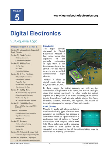
Large Controller Overview24VAC to ControllerJ1GG0J10J11 pLAN V termJ24GND 5 VREFRoom RHU1CO2 SensorU2U3GND VDCSupply Discharge Temperature SensorU4J3GNDOutdoor Air Temperature Sensor Six conductor RJ25 cable Connects to J10F ie l dB u s c ar dSensor B1, B2, B3 CommonsJ2After Cold Coil Temperature SensorRemote DisplayOptional BACnet IP, Modbus TCP, Web UI, Ethernet ConnectionsU5GNDJ12C124VAC for Analog OutputsNO3Exhaust Fan EnableY1Y2Y4ID1ID2Wheel Rotation AlarmID3Occupied/Unoccupied InputDirty Filter d Compressor 4Compressor Fan 1 Enable (VSC)Energy Recovery Wheel EnableCompressor Fan 2 Enable (VSC)Inverter Compressor E-Stop (VSC)C12NC12NO13J18GNDIDC13Staged Compressor 3C9NO18Y5ID13Alarm Dry ContactC9NO9J17ID13HJ82 Position Damper InputID11J23 FBus22 Speed Fan InputNO16J20Discharge Pressure Circuit B (VSC)ID9ID10C8C15J16Exhaust Fan VFD OutputRoom Temperature SensorEconomizer Mode/Output to DampersNC15J22Compressor Limit Circuit DSupply Fan VFD Output24 VACNC8C16J7Compressor Limit Circuit CStaged Compressor 2NO8J15J21ID15HJ19Compressor Limit Circuit BStaged Compressor 1C7ID7GNDCompressor Limit Circuit AHeating EnableID6J6Duct Pressure SensorNO7NO14IDC1Building Pressure Sensor24 VAC from Supply Fan ProvingC4ID4ID8Outdoor Relative Humidity SensorNO6J5Exhaust Fan ProvingNO5J14Unit On/Off InputNO44321Wheel Pressure LimitC4J13Y3C1J26FBus2Supply Fan ProvingSupply Fan EnableVG0J25BMS2Hot Gas Reheat Analog OutputNO2B M S car dHeating Analog OutputCooling/VSC Cond Fan Analog OutputWheel Frost ModeVGJ4Outdoor Air Damper Analog Output24 VAC When Unit OnNO1C13NC13ID18IDC17Optional LonWorks cards arelocated in BMS Card port.8Microprocessor Controller for DOASOptional Modbus RTU/BACnet MSTP connectionsare made to the J26 FBus2 terminal.
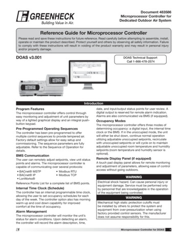
Medium Controller Overview24VAC to ControllerJ1GG0J10J11 pLAN V termJ24GND 5 VREFRefrigerant Pressure Circuit ARefrigerant Pressure Circuit BU2U3F ie l dB u s c ar dSensor B1, B2, B3 CommonsGND VDCAfter Cold Coil Temperature SensorU4J3GNDOutdoor Air Temperature Sensor Six conductor RJ25 cable Connects to J10U1J2Supply Discharge Air TemperatureRemote DisplayOptional BACnet IP, Modbus TCP, Web UI, Ethernet ConnectionsU5GNDJ12C124VAC for Analog OutputsStagged Compressor 3Y1Y2Y3Y4ID1ID2Low Pressure Switch Circuit AID3Unit On/Off InputHigh Pressure Switch Circuit 9Condenser Fan Stage 2 StartNO11Condenser Fan Stage 3 r Compressor E-Stop (VSC)C12NC12NO13J18GNDIDC13J23 FBus2ID13J20Remote Start InputNO17Condenser Fan VFD StartNO10J17ID13HCondensate Drain Pan SwitchJ22ID11J7Freeze Stat InputNO16C9NO9C16ID9ID10Alarm Dry ContactC15J16Dirty Filter InputWheel Rotation AlarmC8NC8NC15GNDExhaust Fan ProvingNO8J15ID8J19Supply Fan VFD OutputEconomizer Mode/Output to DampersC7ID7J6Outdoor Air Damper Output24 VACID6IDC1Outdoor Relative Humidity SensorNO7NO14J21Low Pressure Switch Circuit BC4ID4ID5Stagged Compressor 4NO6J5OA/RA Damper End Switch24 VAC from Supply Fan ProvingNO5J14Occupied/Unoccupied InputC4NO44321High Pressure Switch Circuit AC1J13Supply Fan ProvingNO3J26FBus2Condenser Fan Circuit B or Heating Analog OutputStagged Compressor 2VG0J25BMS2Hot Gas Reheat Analog OutputNO2B M S car dCondenser Fan Circuit A or Heating Analog OutputStagged Compressor 1VGJ4Cooling Analog Output24 VAC When Unit OnNO1C13J8NC13ID18IDC17Optional LonWorks cards arelocated in BMS Card port. Optional Modbus RTU/BACnet MSTP connectionsare made to the J26 FBus2 terminal.Microprocessor Controller for DOAS9
c.pCOe - Expansion Board Overview, Medium Controller ArrangementExt Baud Prot9101112131415Energy Recovery OutputAddress12345678AddressHeating OutputExhaust Fan VFD OutputWheel EnableONOFF24 VAC PowerFurnace Heating Stage 1Furnace Heating Stage 2Space TemperaturePreheater EnableCARELModbusSpace Setpoint Adjustment19.2 K9.6 K38.4 K57.6 KSpace Static PressureSupply Air Duct Static PressureExt. Baud ProtMixed Air TemperatureExhaust Air TemperatureThe expansion board is an I/O module than can be used to monitor additional statuses or provide commands frommedium board controller.10Microprocessor Controller for DOAS
pCOe - 4:1 Furnace OverviewHigh Speed Pressure SwitchIgnition Controller24 VAC24 VAC to ControllerMain Gas ValveIgnition Controller AlarmLow Speed Pressure Switch24 VAC for Analog OutputsHigh Speed Fan24 VACModulating Gas ValveModbus ConnectionModbus Address SwitchespCOe - High Turndown FurnaceLow Speed Pressure SwitchHigh Speed Pressure SwitchIgnition Controller - Small Manifold24 VAC24 VAC to ControllerMain Gas Valve - Small ManifoldMain Gas Valve - Large ManifoldIgnition Controller Alarm24 VAC for Analog OutputsHigh Speed Fan24 VACIgnition Controller - Large Manifold24 VACModulating Gas ValveModbus ConnectionModbus Address Switches Microprocessor Controller for DOAS11
Display UseThe microprocessor controller is located in the unit control center. The face of the controller has six buttons,allowing the user to view unit conditions and alter parameters. The microprocessor controller is pre-programmedwith easy to use menus. A remote display is also available, which connects via the J10 port. A six wire patch cableis needed.Keypad DescriptionButtonDescriptionMain MenuFunctionsPress to go directly to the Main Menu from any screen.From the Main Menu, navigate to the following screens: Unit Enable Unit Status Ctrl Variables Alarm MenuAlarmThe Alarm button flashes when there is an active alarm.Press to view active alarms.Press twice to go to the alarms reset screen.EscapePress from the Main Menu to view the Unit Status screen.Press to go back one menu level.Press when editing a variable to cancel editing.UpPress to navigate through the menus/screens.Press after entering a variable to increase a current value.EnterPress to enter a highlighted menu or screen item.Press to enter a writable variable and press again to confirm the new variable value.DownPress to navigate menus/screens.Press after entering a variable to decrease the current value.Virtual keypad/display on web interface only.These two buttons on the virtual keypad/display are used to simulate two-button actions on the handheldkeypad/display.To simulate pressing two buttons simultaneously:1. Click on 2-Button Click.2. Then, sequentially click on two keypad buttons (Main, Alarm, Escape, Up, Enter, Down).To simulate pressing and holding two buttons simultaneously:1. Click on 2-Button Hold.2. Then, sequentially click on two keypad buttons (Main, Alarm, Escape, Up, Enter, Down).Example of Parameter AdjustmentSupply air low limitAlarm when supply isbelow:35.0º FAlarm delay:300sThe cursor always begins in the upper left corner of the display and will beblinking. Press thebutton to move the cursor down for parameter adjustment.Supply air low limitAlarm when supply isbelow:32.0º FAlarm delay:300sOnce the cursor has reached the desired parameter, press theadjust the value.buttons toSupply air low limitAlarm when supply isbelow:32.0º FAlarm delay:300s12When satisfied with the adjustment, press thebutton to save
Sequence of Operation The microprocessor controller can be configured for air handler, energy recovery, and dedicated outdoor air systems. Each application utilizes similar technologies for heating and cooling: chilled water, hot water, indirect gas, electric heat, packaged DX cooling, and packaged