Transcription
to thecontroller units or to other expansion units.Bosch Security Systems B.V.Installaton manual2021.05 V3 DOC
16en System overviewDSA E-Series (E2800 12-bay)13241SAS port attention LED2SAS port link LED3IOM attention LED4IOM locate LEDThe following table describes the LEDs and their operational states:LEDAttentionLocateStatus indicatorDescriptionAmberThe IOM is not functioning correctly.OffThe IOM is functioning correctly.BlueThere is an active request to physicallylocate the expansion unit.Note: When the Locate LED is activated,the Locate LED on the left end cap ofthe expansion unit is also activated.The Locate LEDs turn off automaticallyafter 30 minutes.OffThere is no active request to locate theexpansion unit.SAS port linkGreenThe SAS port established a link (witheither a controller or another expansionunit).OffNo link is established to another SASport.SAS port attentionAmberOne or more of the links in the port arenot working properly.OffThe port is optimal and no link error hasoccurred.3.2.4LEDs on the drivesThe drives that are installed in the controller unit and the expansion unit include an ActivityLED and an Attention LED.122021.05 V3 DOCInstallaton manualBosch Security Systems B.V.
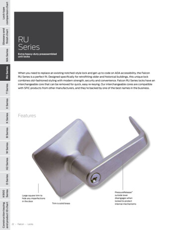
DSA E-Series (E2800 12-bay)1System overview enActivity LED217Attention LEDThe following table describes the LEDs and their operational states:LEDStatus indicatorActivityDescriptionGreenThe drive has power.Blinking greenThe drive has power, and I/O is inprocess.AttentionAmberAn error occurred with the functioningof the drive.3.2.5LEDs on the power-fan canisterThe power-fan canister has LEDs and its own power switch and power outlet. Each 12-baycontroller unit and 12-bay expansion unit has two of these canisters.112Power LED2Attention LEDThe following table describes the LEDs and their operational states:LED iconLED nameStatus indicatorPowerSteady greenDescriptionThe power supply is functioningcorrectly.OffThe power supply failed, the AC switchis turned off, the AC power cord is notproperly installed, or the AC power cordinput voltage is not within margin (thereis a problem at the source end of the ACpower cord).AttentionSteady amberThe power supply or its integrated fanhas a fault.3.2.6Seven-segment-displayEach controller unit has a two-digit, seven-segment display at the back, which shows thecontroller state.Controller stateSeven-segment-displayFunctioning correctlyTray IDNot functioning correctlyDiagnostic codes to help identify errors.Bosch Security Systems B.V.Installaton manual2021.05 V3 DOC
18en System overviewDSA E-Series (E2800 12-bay)3121Tray ID23Diagnostic (dot in the upper left)Heartbeat (dot in the lower right)The following table describes the LEDs and their operational states:LEDTray IDStatus indicatorGreenDescriptionShows the ID of the controller unit whenthe controller operates normally. If thecontroller is not operating normally andthe Diagnostic LED is on, the diagnosticcode is displayed instead.HeartbeatBlinking greenIndicates normal activity.DiagnosticGreenThe seven-segment display shows thediagnostic code.OffThe seven-segment display shows thetray ID.2021.05 V3 DOCInstallaton manualBosch Security Systems B.V.
DSA E-Series (E2800 12-bay)Installation en4Installation4.1Installing a 2U 12-bay unit19You can install the unit in a four-post rack or system cabinet.Observe the following:–You can install the unit in either a square-hole or round-hole rack.–If you are installing the unit in a cabinet not provided by Bosch, you must calculate thethermal output of your equipment and compare the results with the target systemcabinet's thermal rating. You might need to remove the system cabinet doors to improveairflow through the system cabinet.For thermal rating information refer to the rack or system cabinet manuals provided bythe manufacturer.–You must use only the screws that are provided in the kit.Notice!iWhen installing the units, load the cabinet so as not to make it top-heavy. One approach is toplace the controller-unit in the middle portion of the cabinet while allowing room forexpansion units to be placed above and below the controller unit.To install a 12-bay controller or expansion unit:1.Determine where you want to install the unit in the rack or system cabinet.Note: Whenever possible, install the units from the bottom of the rack up, so that you canuse the units underneath as a guide for installing the next set of rails.2.Attach the rails to the rack or system cabinet as follows:–Place the rail inside the rack or system cabinet where you want to install the unit.Align the alignment screws on the rail with the holes on the front post of the rack.–If you have a round-hole rack, remove the eight preinstalled square-hole rackalignment screws and install the eight round-hole rack alignment screws.Note: Ensure that you use the screws that are appropriate for your rack.–Extend the rail to the back post of the rack or system cabinet until the flanges on therail touch the inside of the rack or system cabinet.–Insert one M5 screw through the hole in the front of the rack or system cabinet, andtwo M5 screws through the holes at the back of the rack or system cabinet.–3.Bosch Security Systems B.V.Repeat these steps for the other rail.Place the back of the unit (the end with the connectors) on the rails.Installaton manual2021.05 V3 DOC
20en InstallationDSA E-Series (E2800 12-
4 Installation 19 4.1 Installing a 2U 12-bay unit 19 4.2 Installing the front bezel and end caps21 4.3 Setting the unit ID using the ODP button21 5 Connection 23 5.1 Connecting the expansion units 23 5.1.1 Connecting expansion units to a single controller23 5.1.2 Connecting expansion units to a dual controller25
