Transcription
Application ReportSLVA118A - April 2003 Revised June 2008Linear Regulator Design Guide For LDOsBruce Hunter and Patrick RowlandPMP Portable PowerABSTRACTThis application report evaluates the thermal considerations for linear regulator design. Thethermal equations governing a linear regulator and the evaluation and selection of a linearregulator for a particular design are presented.Contents1Purpose . . . . . . . . . . . . . . . . . . . . . . . . . . . . . . . . . . . . . . . . . . . . . . . . . . . . . . . . . . . . . . . . . . . . . . . . . . . . . 22The Basics . . . . . . . . . . . . . . . . . . . . . . . . . . . . . . . . . . . . . . . . . . . . . . . . . . . . . . . . . . . . . . . . . . . . . . . . . . 23Power Dissipation in the Linear Regulator . . . . . . . . . . . . . . . . . . . . . . . . . . . . . . . . . . . . . . . . . . . . . 34Thermal Equations—Will My Part Work? . . . . . . . . . . . . . . . . . . . . . . . . . . . . . . . . . . . . . . . . . . . . . . . 55Thermal Equations—What to Do if My Part Does not Work? . . . . . . . . . . . . . . . . . . . . . . . . . . . . . 86Summary of Approach and Equations . . . . . . . . . . . . . . . . . . . . . . . . . . . . . . . . . . . . . . . . . . . . . . . . 127Things Often Overlooked . . . . . . . . . . . . . . . . . . . . . . . . . . . . . . . . . . . . . . . . . . . . . . . . . . . . . . . . . . . . 137.1 Differences Between Vendors . . . . . . . . . . . . . . . . . . . . . . . . . . . . . . . . . . . . . . . . . . . . . . . . . . . . . 137.2 The Math Does Not Work. But the Part Does . . . . . . . . . . . . . . . . . . . . . . . . . . . . . . . . . . . . . . . 137.3 Derating . . . . . . . . . . . . . . . . . . . . . . . . . . . . . . . . . . . . . . . . . . . . . . . . . . . . . . . . . . . . . . . . . . . . . . . . 138Other Useful Items . . . . . . . . . . . . . . . . . . . . . . . . . . . . . . . . . . . . . . . . . . . . . . . . . . . . . . . . . . . . . . . . . . 148.1 Linear Regulator Efficiency . . . . . . . . . . . . . . . . . . . . . . . . . . . . . . . . . . . . . . . . . . . . . . . . . . . . . . . 148.2 Input Voltage, Dropout Voltage (VDO), and Low Dropout Regulators (LDO’s) . . . . . . . . . . . . . 169Real World Examples . . . . . . . . . . . . . . . . . . . . . . . . . . . . . . . . . . . . . . . . . . . . . . . . . . . . . . . . . . . . . . . 17Appendix A Thermal Management Vendors . . . . . . . . . . . . . . . . . . . . . . . . . . . . . . . . . . . . . . . . . . . . . . 21Appendix B Additional TI Documentation on Thermal Topics, Packaging, andLinear Regulators . . . . . . . . . . . . . . . . . . . . . . . . . . . . . . . . . . . . . . . . . . . . . . . . . . . . . . . . . . 22Appendix C Other References . . . . . . . . . . . . . . . . . . . . . . . . . . . . . . . . . . . . . . . . . . . . . . . . . . . . . . . . . . 24Trademarks are the property of their respective owners.1
SLVA118AList of Figures1 Potentiometer Model of a Linear Regulator . . . . . . . . . . . . . . . . . . . . . . . . . . . . . . . . . . . . . . . . . . . . . . . . . 32 Power Dissipation Table From the TPS763xx Data Sheet (April 00) . . . . . . . . . . . . . . . . . . . . . . . . . . . . 63 Power Dissipation Table From the TPS768xx Data Sheet (July 99) . . . . . . . . . . . . . . . . . . . . . . . . . . . . 74 Thermal Resistance vs PCB Area for 5 Leaded SOT223 . . . . . . . . . . . . . . . . . . . . . . . . . . . . . . . . . . . . . 75 Thermal and Area Comparison of Packages . . . . . . . . . . . . . . . . . . . . . . . . . . . . . . . . . . . . . . . . . . . . . . . . 86 Steady State Thermal Equivalent Model . . . . . . . . . . . . . . . . . . . . . . . . . . . . . . . . . . . . . . . . . . . . . . . . . . . 97 Comparison of 100-µA lQ PMOS and PNP LDOs . . . . . . . . . . . . . . . . . . . . . . . . . . . . . . . . . . . . . . . . . . . 158 Dropout Voltage Example . . . . . . . . . . . . . . . . . . . . . . . . . . . . . . . . . . . . . . . . . . . . . . . . . . . . . . . . . . . . . . . 169 Power Dissipation Table From the TPS76318 Data Sheet (May 01) . . . . . . . . . . . . . . . . . . . . . . . . . . . 1710 From the REG101 Data Sheet (July 01) . . . . . . . . . . . . . . . . . . . . . . . . . . . . . . . . . . . . . . . . . . . . . . . . . . 181PurposeThe purpose of this application report is to explore the thermal considerations in using linearregulators. When finished, the reader will understand the following: Why thermal considerations are important for every linear regulator design The thermal equations governing a linear regulator How to evaluate/choose linear regulators for a designIn addition, this document provides a summary of approach and equations in Chapter 6. Thischapter is designed as a one page reference for the reader.2The BasicsThe first considerations for choosing a linear regulator are input voltage (VI), output voltage (VO),and output current (IO). These are necessary for selecting the appropriate linear regulator for anapplication. Other very necessary, although often over looked, considerations in linear regulatorselection are the application specific thermal considerations. These thermal considerations arethe topic of this application report.For a short review on the theory of operation, a linear regulator has a pass element that ismanaged by the controller portion of the IC. The controller monitors the feedback and eitheropens or restricts the pass element to maintain a constant output voltage over variation in theinput voltage and the output current required by the load. A helpful analogy is to think of thecontrol portion of the regulator as a lamp dimmer switch or potentiometer.Where altering a dimmer switch varies the amount of light, a linear regulator alters the passelement to maintain a constant output voltage. We know that Ohm’s law states V I R. If alinear regulator maintains a constant output voltage (V) over varying input voltage and outputcurrent into the load, it follows that R is what is being controlled by the regulator. So that is howwe maintain the output voltage, but where does the heat come from?The difference between the input voltage and output voltage with a fixed load current is energythat is dissipated by the linear regulator. Nearly all of this energy is converted to heat. How tocalculate and manage this heat is the topic of this application report.2Linear Regulator Design Guide For LDOs
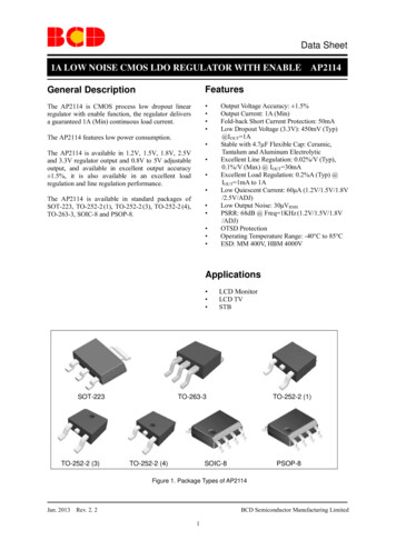
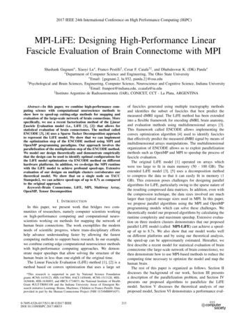
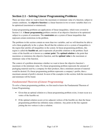
SLVA118A3Power Dissipation in the Linear RegulatorTo help us understand the power dissipation requirements at a high level, we use thepotentiometer model shown in Figure 1.Pass ElementVO and IOVI and IIVREFFeedbackElementREFRLError AmpFeedback VoltageLinear RegulatorFigure 1. Potentiometer Model of a Linear RegulatorWhile regulating, the pass element is always on in a linear regulator. Using the potentiometermodel as a guide and remembering Kirchoff’s current law, we can see how the input currentmust be equal to the output current. Armed with that knowledge, we can look at power andpower dissipation in our system.Since our system must observe physics and the conservation of energy, we can use ourknowledge of VI, VO, and current to identify how power is distributed in our model. We start withthe power placed into our system:(1)PI lI VIFollowing the same thought process, the power delivered to the load is:(2)PO lO VONow, looking back at Figure 1 we remember that II roughly equals IO. The difference between PIand PO is the power that is burned or dissipated by the regulator. The quantity of dissipatedpower (PD) can be extracted by the following equation:(3)PD PI POPD is almost entirely heat dissipated by the linear regulator thus PD is precisely what we areconcerned with thermally when selecting a package. If we use equation 3 to arrive at amaximum PD for an application, we refer to that variable as PD(max). Making this distinctionbecomes useful in later equations.Before moving on, we should take a moment to look at equation 3 in slightly more detail.Equation 3 can be rewritten from before as:(4)PI PO PDIn most applications, the approximation of assuming II IO is sufficient for thermal calculations.The model we have used up to now has ignored the quiescent current of the linear regulator. Ifwe add the quiescent power (PQ) required by the linear regulator, equation 4 changes to:(5)PI PO PD PQLinear Regulator Design Guide For LDOs3
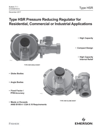
SLVA118APQ is derived by multiplying the input voltage by the quiescent current of the regulator.Thermally, PQ is usually insignificant, as it is orders of magnitude smaller than the outputcurrent. For example, the TPS789xx series of 100 mA (or 0.1 A) low dropout regulators (LDO)has a typical IQ of 17 µA (or 0.000017 A). In an example where the TPS78925 is used with VI 3.3 V, VO 2.5 V, and IO 100 mA we can see how PQ (56 µW) is substantially smaller than PD(80 mW). Thus, out of practicality and for simplicity we examine the thermal considerations forlinear regulators based on equation 4 ignoring quiescent current.Quiescent current can have a significant impact on efficiency in power sensitive applications.This is covered briefly in Other Useful Items (Chapter 8) and in more detail in the Efficiencyportion of TI application reports SLVA079 – Understanding the Terms and Definitions of LowDropout Voltage Regulators and SLVA072 – Technical Review of Low Dropout VoltageRegulator Operation and Performance, as listed in Appendix B.Another topic that warrants a brief commentary is steady state verses transient or pulsed currentdemand of a load from its power supply. In many applications, an LDO supplies bothsteady-state and pulsed load current. A given design may have low duty cycle load transientcurrents in addition to the steady-state load. The current transients can approach the internalfixed current limit of the LDO, which is normally between 2 and 4 times the continuous currentrating of the device. However, if we have an excessive junction temperature rise, thermalshutdown is activated. The thermal shutdown junction temperature typically occurs at 150 C.Whether the thermal design is based upon the average load current or designed to handle themaximum peak current depends upon the duration and frequency of occurrence of the loadtransient. In either case we are safe if we do not exceed the absolute maximum junctiontemperature rating of the device.Returning to PD, the power ratings of LDOs are normally based upon steady state operatingconditions. Steady-state conditions between junction and case are typically achieved in lessthan 10 seconds where several minutes may be required to achieve steady-state junction toambient. Transient thermal impedance illustrates the thermal response to a step change inpower. This information is provided for discrete power devices and normally not for integratedcircuits. The transient thermal response is a function of die size, die attach, and package. Welimit the scope of our discussion to steady-state thermal resistance.By utilizing the thermal equations that follow in Chapter 4, we ensure that the junctiontemperature of our linear regulator remains within acceptable limits. A semiconductor’s longterm reliability is affected by its operating junction temperature; therefore, it is important tomaintain a junction temperature that falls below the manufacturers absolute maximum operatingjunction temperature. This restriction limits the device’s power dissipation capability. To do this,we need to calculate the maximum allowable dissipation, PD(max), and the actual dissipation, PD,which must be less than or equal to PD(max). How to make these calculations is what we explorenext.Factors which influence thermal performance include PCB design, component placement,interaction with other components on the board, airflow, and altitude. There is no substitute for asystem level thermal analysis to ensure a successful design.4Linear Regulator Design Guide For LDOs
SLVA118A4Thermal Equations—Will My Part Work?With an understanding of PD, now we can examine the thermal considerations PD generates.The following equation links PD to the thermal specifications for a linear regulator:(6)PD (TJ TA)/θJAWhereθJA theta ja (junction to ambient) C/WTJ junction temperature rating CTA ambient temperature CPD power dissipated in watts WEquation 6 enables us to relate power dissipation with the thermal characteristics of thedie/package combination and ambient temperature. It is useful to manipulate equation 6 to:(7)θJA (TJ TA)/PDEquation 7 is useful as TJ, TA, and PD(max) (see equation 3) are often known quantities in anapplication. By using these three known values, equation 7 will tell us what value of θJA isnecessary in order to have enough thermal conductance or thermal dissipation capability for ourlinear regulator in a particular application. Having the appropriate thermal conductance ensuresthat the PD(max) does not exceed the PD that the linear regulator is capable of supporting.Exceeding the PD that the regulator can support creates extreme junction temperatures which inturn impact the reliability of the design. For the remainder of this application note, if we usePD(max) in equation 7 to determine a maximum θJA for an application, we are referring to it asθJA(max).In looking at equation 7, θJA decreases with an increase in TA or PD. It follows that the lower θJAis from equation 7, the more challenging the thermal requirements. Additionally, the lower a θJAis specified in a data sheet, the better thermal conductance a device exhibits.Most vendors specify θJA in a linear regulator data sheet as the thermal specification. At TI, thiswas the case until recently and is still the case for higher power, higher output current linearregulators. To make regulator selection easier, TI has moved to a different way of representingthe same information. As an example, data sheet examples have been provided below. (NOTE:xx is the voltage option. For example: TP
we maintain the output voltage, but where does the heat come from? The difference between the input voltage and output voltage with a fixed load current is energy that is dissipated by the linear regulator. Nearly all of this energy is converted to heat. How to calculate and manage this heat is the topic of this application report. SLVA118A Linear Regulator Design Guide For LDOs 3 3 Power .