Transcription
F4A42/F4A51 Operation, Diagnosis and Repair
F4A42/F4A51 Operation, Diagnosis and Repair
F4A42/F4A51 Operation, Diagnosis and RepairTABLE OF CONTENTSINTRODUCTION AND OBJECTIVES . 1F4A42 AND F4A51 AUTOMATIC TRANSAXLE OVERVIEW. 2ACRONYMS . 4GENERAL DESCRIPTION . 5MODULE 1 F4A42/F4A51 TRANSAXLE IDENTIFICATION. 7IDENTIFICATION. 7MODEL DESIGNATION. 7AUTOMATIC TRANSMISSION FLUID . 9ACTIVITY 1.1 TRANSAXLE IDENTIFICATION . 10MODULE 2 MECHANICAL COMPONENTS . 11MECHANICAL COMPONENTS . 11TRANSAXLE CASE . 11TORQUE CONVERTER . 13MANUAL CONTROL LEVER . 14VALVE BODY LOCATION. 15ACCUMULATORS . 18ACCUMULATOR SPRINGS. 18ACTIVITY 2.1 VALVE BODY REMOVAL . 19TASK ONE: VALVE BODY REMOVAL. 19TASK TWO: STRAINER AND 2ND BRAKE SEAL REMOVAL . 20TASK THREE: ACCUMULATOR REMOVAL . 21TASK FOUR: MANUAL LEVER REMOVAL . 21SPEEDOMETER GEAR (2001 MODEL YEAR WITH VSS) . 22OIL PUMP. 23OIL FILTER . 24ACTIVITY 2.2 TRANSAXLE DISASSEMBLY . 25TASK ONE: CASE SEPARATION . 25TASK TWO: OIL FILTER, OIL PUMP AND INPUT SHAFT REMOVAL. 25TASK THREE: CLUTCH AND GEARTRAIN REMOVAL . 26TASK FOUR: OUTPUT SHAFT REMOVAL. 27CLUTCHES . 30Underdrive Clutch30Reverse Clutch and Overdrive Clutch32Balance Pistons34BRAKES (HOLDING CLUTCHES) . 35Low/Reverse Brake35Second Brake36One-Way Clutch37PLANETARY GEAR SETS . 38DIFFERENTIAL. 39Transfer Drive Gear40Output Shaft/Transfer Driven Gear41MODULE 3 POWERFLOW . 42i
F4A42/F4A51 Operation, Diagnosis and RepairPARK AND NEUTRAL .42REVERSE .43FIRST GEAR .44SECOND GEAR .45THIRD GEAR .46FOURTH GEAR.47ACTIVITY 3.1 PLANETARY CARRIER .48CLUTCH AND GEARTRAIN .49ACTIVITY 3.2 GEAR RATIOS .50ACTIVITY 3.3 TRANSAXLE ASSEMBLY .51TASK ONE: TRANSFER GEAR INSTALLATION.51TASK TWO: L/R AND 2ND BRAKE SET-UP.51TASK THREE: OUTPUT SHAFT INSTALLATION AND SETUP .53TASK FOUR: PARKING PAWL INSTALLATION .54TASK FIVE: PLANETARY CARRIER INSTALLATION .54TASK SIX: UNDERDRIVE AND OVERDRIVE/REVERSE CLUTCH SETUP .55TASK SEVEN: OIL PUMP INSTALLATION .56TASK EIGHT: CONVERTER HOUSING INSTALLATION .56MODULE 4 VALVE BODY/HYDRAULIC CONTROL SYSTEM.58CHECK BALLS.60PRESSURE CONTROL VALVES AND SOLENOID VALVES .62Operation62REGULATOR VALVE.63TORQUE CONVERTER PRESSURE CONTROL VALVE.64DAMPER CLUTCH CONTROL VALVE AND DAMPER CLUTCH SOLENOID VALVE.66Operation66HYDRAULIC OPERATION.68Park and Neutral68Reverse70First Gear72Second Gear74Third Gear76Fourth Gear78MANUAL VALVE .80Operation (P/N)80Operation (R)82Operation (D)84SWITCH VALVE .86FAIL-SAFE VALVE A .90FAIL-SAFE VALVE B .90ACTIVITY 4.1 VALVE BODY DISASSEMBLY.91ACTIVITY 4.2 HYDRAULIC OPERATION .92MODULE 5 ELECTRONIC CONTROL SYSTEM.97ELECTRONIC COMPONENTS .97ii
F4A42/F4A51 Operation, Diagnosis and RepairPOWERTRAIN CONTROL MODULE (PCM) . 98PCM CONNECTOR . 99SYSTEM CONSTRUCTION DIAGRAM. 100SENSORS AND ACTUATORS . 101INPUT SHAFT SPEED SENSOR/OUTPUT SHAFT SPEED SENSOR . 102Circuit Operation103Vehicle Speed Signal103ACTIVITY 5.1 INPUT SHAFT AND OUTPUT SHAFT SPEED SENSORS . 104CRANKSHAFT POSITION (CKP) SENSOR . 106Circuit Operation106ACTIVITY 5.2 CRANKSHAFT POSITION SENSOR. 107THROTTLE POSITION SENSOR . 108Circuit Operation108Throttle Position Sensor Adjustment108ACTIVITY 5.3 THROTTLE POSITION SENSOR . 110TPS WIRE COLOR110VOLTAGE READING110ATF TEMPERATURE SENSOR . 112Circuit Operation112ATF TEMPERATURE CONTROL . 113ACTIVITY 5.4 AUTOMATIC TRANSAXLE FLUID TEMPERATURE SENSOR . 114Park/Neutral Position Switch115Circuit Operation115ACTIVITY 5.5 TRANSAXLE RANGE SWITCH/PARK/ NEUTRAL POSITIONSWITCH (INHIBIT SWITCH) CONTINUITY CHECK . 116TRANSAXLE CONTROL . 118ACTIVITY 5.6 PARK/NEUTRAL POSITION SWITCH AND CONTROL CABLEADJUSTMENT. 119A/C DUAL PRESSURE SWITCH. 120Circuit Operation120STOPLIGHT SWITCH . 120Circuit Operation121AUTO-CRUISE CONTROL . 122Circuit Operation122ACTIVITY 5.7 STOPLIGHT SWITCH CHECK . 123SOLENOID VALVES . 124Circuit Operation126ACTIVITY 5.8 SOLENOID VALVE CHECK . 127TASK ONE – ACTUATOR TEST . 127TASK TWO – VIEW DATA LIST. 128AUTOMATIC TRANSAXLE (A/T) CONTROL RELAY. 129Circuit Operation130ACTIVITY 5.9 A/T CONTROL RELAY CHECK . 131AUTOSTICK SELECT SWITCH . 132Circuit Operation133iii
F4A42/F4A51 Operation, Diagnosis and RepairACTIVITY 5.10 AUTOSTICK SELECT SWITCH .134SWITCH POSITION . 134UPSHIFT. 134DOWNSHIFT. 134CONTROL OVERVIEW . 135Shift Control135Shift Pattern Control135Select Switch and Shift Switch135AUTOSTICK . 136ADAPTIVE MEMORY. 138Hydraulic Control During Gear Shifts139Clutch-to-Clutch Control139Feedback Control and Learning Control140Functional Learning140Driver Learning140Damper Clutch Control142LIMP-IN (FAIL-SAFE) FUNCTION AND DIAGNOSIS. 144LIMP-IN (FAIL-SAFE) OPERATION (CONTROL RELAY OFF) . 144FAIL-SAFE VALVE A OPERATION . 146FAIL-SAFE VALVE B OPERATION . 146MAJOR LIMP-IN. 146MINOR LIMP-IN . 146Diagnostic Codes146Display Sequence147Memorization147Diagnostic Code Deletion147DATA LIST . 148ACTUATOR TEST. 149AUTOSTICK STOP COMMAND (MPI) . 149MODULE 6 DIAGNOSIS .150N-RANGE LAMP. 150ACTIVITY 6.1 N-RANGE LAMP FUNCTIONS .151ACTIVITY 6.2 TORQUE CONVERTER STALL TEST .152TORQUE CONVERTER STALL TEST RESULTS . 153ACTIVITY 6.3 CLUTCH TESTS .154ACTIVITY 6.4 HYDRAULIC PRESSURE TEST.155ACTIVITY 6.5 STANDARD HYDRAULIC PRESSURE TEST .156SPECIAL TOOLS .158GLOSSARY .166iv
F4A42/F4A51 Operation, Diagnosis and Repairv
F4A42/F4A51 Operation, Diagnosis and Repairvi
F4A42/F4A51 Operation, Diagnosis and RepairINTRODUCTION AND OBJECTIVESIntroduced in the 2001 Stratus and Sebring Coupes, the F4A42 and F4A51 are a newgeneration of fully electronically shifted transaxles. By using a fully electronicallycontrolled design, the driver experiences a consistent shift quality and feel.The purpose of this course is to provide training on DaimlerChrysler Corporations“F4A42 and F4A51 Electronic Transmission Operation, Diagnosis and Repair”.Upon completion of this course you will be able to: Identify the F4A42 and F4A51 automatic transaxle by decoding the ID tag.Disassemble, evaluate, reassemble, setup and make all necessaryadjustments to the transaxle and all subassemblies.Identify all mechanical components.Demonstrate all gear ratios using a planetary gear stack.Identify and describe all hydraulic components.Diagnose hydraulic malfunctions.Identify the hydraulic flow and solenoid actuation necessary to achieve allgear ratios.Perform electrical related DRBIII activities to identify all direct inputs andoutputs.Interpret appropriate shift schedules and determine if there is a malfunctionor if the vehicle is operating properly.Diagnose and recommend the proper steps needed to perform a repair.1
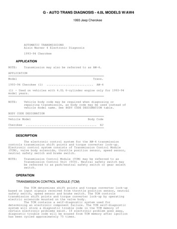
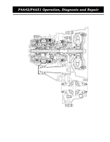
F4A42/F4A51 Operation, Diagnosis and RepairF4A42 AND F4A51 AUTOMATIC TRANSAXLE OVERVIEWAs with other electronically controlled transaxles the F4A42 and F4A51 transaxlesutilize a torque converter and gear train (fig. 1). The torque converter is a 3-element,single-stage, 2-phase type with a built-in lock-up clutch. The gear train consists ofthree multi-disc clutches, two multi-disc brakes, a one-way clutch and two planetarygear sets. Each planetary gear set consists of a sun gear, carrier, pinion gears, andannulus gear. These newly developed transaxles combine the highest-precisionelectronic and mechanical technology to provide a new era in automatic transaxleperformance.Figure 1 F4A42/F4A51 Transaxle (2001 Model Year Shown)2
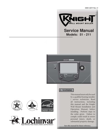
F4A42/F4A51 Operation, Diagnosis and Repair12345Rear of Transmission6 One-Way ClutchOverdrive Clutch7 Output GearReverse Clutch8 Underdrive ClutchSecond Brake9 Front of TransmissionLow/Reverse BrakeFigure 2 F4A42/F4A51 Geartrain3
F4A42/F4A51 Operation, Diagnosis and RepairACRONYMSThe following is a list of acronyms used throughout this publication: CMPNPRCTCCTSBUD2ndAutomatic TransaxleAutomatic Transmission FluidDamper Control ClutchDiagnostic Readout BoxDiagnostic Trouble CodeElectronic Control Unit (Manual Transmission)Electronically Modulated Converter ClutchForm-in-Place GasketFront Wheel DriveOne Thousand OhmsLow-Reverse BrakeMopar Diagnostic SystemOverdrive ClutchOver Running ClutchOne-Way ClutchPowertrain Control Module (Automatic Transmission)Park/Neutral Position SwitchReverse ClutchTorque Converter ClutchTechnical Service BulletinUnderdrive ClutchSecond Brake4
F4A42/F4A51 Operation, Diagnosis and RepairGENERAL DESCRIPTIONThe F4A42 and F4A51 automatic transaxles come in two models. Although they aresimilar in appearance there are several mechanical differences. Refer to Table 1 formodel specifications.Table 1 F4A42/F4A51 Transaxle SpecificationsITEMSSPECIFICATIONSTransaxle modelF4A42F4A51Engine model4G64 (2.4L)6G72 (3.0L)Torque converterType3-element, 1-stage, 2-phaseTorque converterclutchProvided (3rd to 4th)Stall torque ratio1.852.04Transaxle type4-speed forward, 1-speed reverse full automaticGear 120.731Reverse2.4802.720Final gear ratio (differential gear ratio)4.0423.735Number of underdrive clutch discs4Number of overdrive clutch discs4Number of reverse clutch discs2Number of low/reverse brake discs6Number of second brake discs354
F4A42/F4A51 Operation, Diagnosis and RepairNotes:6
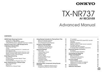
F4A42/F4A51 Operation, Diagnosis and RepairMODULE 1F4A42/F4A51 TRANSAXLE IDENTIFICATIONIDENTIFICATIONThe F4A42 transaxle is found behind the 2.4L engine and the F4A51 transaxle isnormally found behind the 3.0L engine. The bell housing bolt patterns are differentand do not interchange between the 2.4L and 3.0L engines.MODEL DESIGNATIONA model number consisting of 11 digits is used to identify the transaxles. Each digitor pair of digits is used to provide specific information (fig. 3). F Drive Axle4 Forward SpeedsA Transaxle Type42 Capacity (duty rating)K Manufacturing Plant1 Development (build) SequenceM Final Drive Ratio8 Speedo Gear RatioA One-Way Clutch & Planetary Ratio5 Manufacturing Use OnlyProper identification of the F4A42 and F4A51 transaxles is important for thefollowing reasons: Ordering partsSTAR assistanceZone assistanceResearching TSB applicability7
F4A42/F4A51 Operation, Diagnosis and RepairFigure 3 Model Designation Identification8
F4A42/F4A51 Operation, Diagnosis and RepairAUTOMATIC TRANSMISSION FLUIDThe type of automatic transmission fluid used in the F4A42 and F4A51 automatictransaxles is Diamond ATF SP IIM, Diamond ATF SP III or a Mopar equivalent. Theuse of a newly developed ATF (ATF-SPII) ensures a longer ATF service life. Fluidinformation is found on a label at the top of the dipstick.Caution:Using the incorrect transmission fluid may cause poor shift qualityor torque converter shudder.If the fluid level is low, the oil pump draws in air along with the fluid, which causesbubbles to form inside the hydraulic circuit. This causes a hydraulic pressure drop,late shifting, slipping of the clutches and brakes, and transmission overheating.If there is too much fluid, the internal rotating transaxle components can churn upthe fluid, causing foam and a low fluid level indication. In either case, air bubblescan cause overheating and oxidation of the fluid which can interfere with normalvalve, clutch, and brake operation. Foaming can also result in fluid escaping from thetransaxle vent, and may appear as a leak.9
F4A42/F4A51 Operation, Diagnosis and RepairACTIVITY 1.1TRANSAXLE IDENTIFICATIONFor this activity you will identify the transaxle on the bench using the ServiceManual.1. Using a F4A42 or F4A51 Transmission on a bench, locate and identify thefollowing transmission components: Identification LabelInput and Output Speed SensorsVehicle Speed Sensor (VSS)-(2001 Model Year Only)Transaxle Solenoid Connector2. Record the transmission tag number3. Record the first five characters of the tag numberThese characters represent the type and capacity of the transaxle.4. Record the next two characters of the tag numberThese numbers represent the manufacturing plant and development sequence.Example: K1 – the transaxle was built in Kyoto works, first design.5. Record the last four characters of the tag number6. Why is the information contained in the tag number important?7. How do you remove the solenoid connector from the transmission?8. The fluid identification information is stamped in the dipstick.TrueFalse10
F4A42/F4A51 Operation, Diagnosis and RepairMODULE 2MECHANICAL COMPONENTSThis module covers the following transaxle components:MECHANICAL COMPONENTS Torque converter Oil pump Clutches Brakes (holding clutches) Planetary gear setCaution:1The second brake retainer oil seal (fig. 4) must be removed beforeremoving the transaxle powertrain components from the case ordamage to the seal will occur.Strainer2 Second Brake Retainer Oil SealFigure 4 Second Brake Retainer Oil SealTRANSAXLE CASEThe F4A42 and F4A51 transaxles utilize a split case design consisting of theconverter housing, transaxle case, rear cover, and valve body cover (fig. 5). The casehalves must be separated to gain access to the filter. All gasket surfaces are sealedwith form-in-place gasket (FIPG). Also, the names of hydraulic check ports areembossed on the casing to facilitate hydraulic checks (fig. 6).11
F4A42/F4A51 Operation, Diagnosis and Repair123Transaxle CaseRear CoverValve Body Cover4 Oil Filter5 Converter Housing6 Bearing RetainerFigure 5 Transaxle Casing12345DCC Release Check Port6 Transaxle CaseReverse Clutch Check Port7 Low/Reverse Brake Check PortRear Cover8 Underdrive Clutch Check PortOverdrive Clutch Check Port9 2nd Brake Check PortTorque Converter Housing10 DCC Applied Check PortFigure 6 Hydraulic Check Ports12
F4A42/F4A51 Operation, Diagnosis and RepairTORQUE CONVERTERThe torque converter in the F4A42 and F4A51 is a damper-sprung lock-upmechanism (fig. 7). 1The torque converter consists of an impeller, a turbine and a stator.The rotating impeller throws oil against the turbine causing it to rotate theinput shaft of the transaxle.The turbine also throws oil against the stator causing it to rotate.The stator consists of a vaned cover and an overrunning clutch. Because thestator is allowed to turn in one direction only torque is multiplied. If thestator fails there is no torque multiplication, resulting only in a fluidcoupling.The torque converter achieves lock-up by applying the damper clutchaccording to load, engine temperature and speed.Damper SpringFigure 7 Torque Converter13
F4A42/F4A51 Operation, Diagnosis and RepairMANUAL CONTROL LEVERThe manual control lever is fitted to the top of the valve body and is linked to theparking roller rod and manual control valve pin (fig. 8). A detent mechanism isprovided to improve the gearshift feeling during manual selection. When the manualcontrol lever is moved to the parking position, the parking roller rod moves along theparking roller support and pushes up the parking sprag. As a result, the parkingsprag meshes with the transfer driven gear (parking gear), locking the output shaft.To minimize the operating force required, a roller is fitted to the end of the rod.Caution:1234When removing the park mechanism, the 2nd O-ring comes offbefore removing the shaft to keep a piece from lodging in thepinhole.Parking Roller Rod5 Parking GearInhibitor Switch6 Parking SpragParking Roller Support7 Detent SpringSpring8 Manual Control LeverFigure 8 Manual Control Lever14
F4A42/F4A51 Operation, Diagnosis and RepairVALVE BODY LOCATIONThe valve body is mounted vertically to the side of the automatic transaxle toward thefront of the vehicle, reducing the automatic transaxles overall height (fig. 9). Asolenoid valve and pressure control valve are used for each clutch and brake. Theline pressure is regulated by a regulator valve. In the event of a solenoid valve fault,the switch valve and limp-in valve arrangement enables operation in 3rd gear orreverse.Note:1Before removing the valve body you must remove the solenoid harnessconnector snap ring.Valve BodyFigure 9 Valve Body Location15
F4A42/F4A51 Operation, Diagnosis and RepairThere are several bolts of different lengths used to mount the valve body to thetransaxle (figs. 10 and 11).Caution:1234When removing the valve body, there are four 70mm bolts that donot need to be removed. Removal of these four bolts causes the topof the valve body to come off and parts may be lost or damaged.105 mm5 38 mm75 mm6 20 mm70 mm (Do Not Remove)7 Fluid Temperature Sensor45 mmFigure 10 Valve Body Mounting Bolt Location16
F4A42/F4A51 Operation, Diagnosis and Repair123105 mm75 mm70 mm4 45 mm5 38 mm6 20 mmFigure 11 Valve Body Mounting Bolts17
F4A42/F4A51 Operation, Diagnosis and RepairACCUMULATORSAn accumulator is a spring-loaded device designed to cushion clutch engagementaccording to engine torque. The accumulator absorbs a certain amount of fluidpressure from the circuit during clutch engagement. Without an accumulator, therapid build up of line pressure causes a very quick clutch apply which creates aharsh shift. The clutches and brakes shown in Table 2 below have accumulators intheir circuits.Table 2 AccumulatorsFunctional NameAccumulator NumberLow/Reverse Brake1Underdrive Clutch2Second Brake3Overdrive Clutch4ACCUMULATOR SPRINGSThe accumulator springs are specific to the accumulator function. The springs arerated at different levels of stiffness, depending on application, and must be installedinto the correct accumulator bore or transmission shift quality may be affected.Accumulator springs can be identified by a blue colored pattern on the end of thespring. Table 3 below aids in identifying the springs.Table 3 Accumulator SpringsNumber of SpringsNameIdentification “Bluing”2Low-Reverse BrakeNone2Underdrive ClutchHalf of the surface2Second BrakeWhole surface1Overdrive ClutchNone18
F4A42/F4A51 Operation, Diagnosis and RepairACTIVITY 2.1VALVE BODY REMOVALFor this activity you will remove the valve body, 2nd brake seal, accumulators andmanual lever from the transaxle on the bench.TASK ONE: VALVE BODY REMOVAL1. Remove the bolts securing the valve body to the transaxle case, noting the numberand length of each bolt.2. Do not remove the four 70 mm bolts as shown in figure 12.170 mm – 3 (Do Not Remove)270 mm –1 (Do Not Remove)Figure 12 70 mm Bolts (Not To Be Removed)19
F4A42/F4A51 Operation, Diagnosis and RepairACTIVITY 2.1VALVE BODY REMOVAL (CONTINUED)3. Remove the valve body from the case. Be careful not to lose the two vent checkballs.4. Why is it important that you do not remove the 70 mm bolts before removing thevalve body from the case?5. How is the solenoid harness removed?TASK TWO: STRAINER AND 2ND BRAKE SEAL REMOVAL1. Remove the strainer and 2nd brake retainer oil seal after removing the valve body.Why is it important to remove the 2nd brake retainer oil seal at this time?2. Is the second brake seal oriented?YesNo20
F4A42/F4A51 Operation, Diagnosis and RepairACTIVITY 2.1VALVE BODY REMOVAL (CONTINUED)TASK THREE: ACCUMULATOR REMOVAL1. Remove the four accumulators.2. Remove the accumulator springs.3. How are the accumulator springs identified?4. Which clutch or brake has only one accumulator spring?a. L/Rb. UDc. ODd. 2nd BrakeTASK FOUR: MANUAL LEVER REMOVAL1. Remove the manual lever shaft pin.2. Push the lever shaft up through the case.3. Remove the two rubber O-rings from lever shaft. (fig. 13).4. Remove the lever shaft.Caution:12When removing the park mechanism, the O-rings come off beforeremoving the shaft to keep from getting a piece caught in thepinhole.O-ringsRetainer Pin3Manual LeverFigure 13 Manual Shaft O-rings21
F4A42/F4A51 Operation, Diagnosis and RepairSPEEDOMETER GEAR (2001 MODEL YEAR WITH VSS)The speedometer gear has a built-in vehicle speed sensor (fig. 14). Mechanically thespeedometer gear on the F4A42 and F4A51 is different by the number of teeth on thegear. The F4A42 has 29/36 gear ratio while the F4A51 has a 28/36 gear ratio. Referto Table 4.Table 4 F4A42/F4A51 Gear RatiosSpeedometer Gear Ratio1F4A42F4A5129/3628/36Vehicle Speed SensorFigure 14 Speedometer Gear22
F4A42/F4A51 Operation, Diagnosis and RepairOIL PUMPThe F4A42 and F4A51 transaxles use the same oil pump. The oil pump is a rotortype pump consisting of a two-piece housing and a gear (fig. 15). If the pump fails,do not try to service it. Replace the assembly.Caution:The oil pump is not serviceable; it must be replaced as a pumpassembly. Do not disassemble the pump. Improper alignmentduring assembly causes pump failure and causes damage to thetransaxle.Figure 15 Oil Pump23
F4A42/F4A51 Operation, Diagnosis and RepairOIL FILTERThe F4A42 and F4A51 transaxles use a non-woven type oil filter. The filter is locatedin the transaxle case (fig. 16). To service the oil filter the transaxle must be removedfrom the vehicle and the case halves split.1Main Oil FilterFigure 16 Oil Filter24
F4A42/F4A51 Operation, Diagnosis and RepairACTIVITY 2.2TRANSAXLE DISASSEMBLYFor this activity you will disassemble a F4A42 or F4A51 transaxle on the bench usingthe service manual.TASK ONE: CASE SEPARATION1. Remove the input/output speed sensors and VSS (if equipped), manual controllever and the park/neutral position switch.2. What is the measured input shaft endplay?3. What is the input shaft endplay standard value (specification)?4. Separate the converter housing and transaxle case.5. What are the two O-rings located between the case halves used for?6. Remove the differential assembly from the case.TASK TWO: OIL FILTER, OIL PUMP AND INPUT SHAFT REMOVAL1. Remove the oil filter.2. Locate, identify and remove the oil pump.3. What special tool number is used to remove the oil pump assembly?4. Do not disassemble the oil pump.Why is it important not to disassemble the oil pump?5. Remove the input shaft, UD clutch and hub.25
F4A42/F4A51 Operation, Diagnosis and RepairACTIVITY 2.2TRANSAXLE DISASSEMBLY (CONTINUED)TASK THREE: CLUTCH AND GEARTRAIN REMO
The F4A42 transaxle is found behind the 2.4L engine and the F4A51 transaxle is normally found behind the 3.0L engine. The bell housing bolt patterns are different and do not interchange between the 2.4L and 3.0L engines. MODEL DESIGNATION A model number consisting of 11 digits is used to identify the transaxles.