Transcription
AMBIENT GENERAL MERCHANDISERGLASSFRONT VENDORSERVICEMANUALMODELS:3605 – 5 WIDE3606 – 6 WIDEMAY 20193605 3606 4225133 Rev C
3605 360624225133 Rev C
Table of ContentsSAFETY WARNINGS & SPECIFICATIONS . 4INTRODUCTION . 5GENERAL MERCHANDISER . 5AMERICANS WITH DISABILITIES ACT (ADA). 5SERVICING . 5AT A GLANCE . 6UNPACKING . 7INSTALLATION . 7REMOVING THE SWING DOOR . 7REMOVING THE PULL-OUT DOOR . 8POWER CORD . 10POSITIONING & LEVELING VENDOR. 10GROUNDING (EARTHING) & ELECTRICAL . 10MAIN POWER SWITCH . 10LOADING PRODUCTS. 11SPIRAL ADJUSTMENT . 12EVOKE 6 TRAYS . 12TRAY REMOVAL . 12DUAL PINION GEAR . 13DOOR SWITCH. 14SERVICE MODE . 15MOTOR PAIRING . 15INSTALLING A COIN CHANGER . 16CASH BOX . 16BILL VALIDATOR OPERATION (OPTIONAL) . 17IVEND OPTICAL SENSING. 17PREVENTIVE MAINTENANCE . 18PARTS ORDERING PROCEDURE . 19BEFORE CALLING FOR SERVICE . 19EVOKE 5 ELECTRICAL SCHEMATIC . 20EVOKE 6 ELECTRICAL SCHEMATIC . 21FLEX CONTROL BOARD LAYOUT . 22NOTES: . 233605 360634225133 Rev C
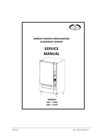
SAFETY WARNINGS & SPECIFICATIONSWARNINGS1.2.3.4.5.6.In cases where there is no fuse in the plug of the power cord, the primary over-current electrical protectionis provided by the buildings power distribution board.This vendor is not intended for use by young children or the infirm unless aided or supervised by an adultor an abled-bodied person.This vendor must be level for proper operation, door to door alignment, cabinet to door alignment foracceptance of coins through the coin mechanism see Installation section pg. 9This vendor is designed to dispense pre-packaged products for hygiene & safety purposes and no surfacesshould ever come into direct contact with the food to be consumed.For the purposes of food handling, replenishing and hygiene maintenance operating personnel should havereceived the required training and instruction as mandated by the local authority responsible.This vendor is designed for indoor use and must not be installed in a location where a water hose/jet couldbe used.DIMENSIONS & WEIGHTSTYPEMANUAL REVISION HISTORY3605 – 5 Wide3606 – 6 WideMODEL3605/3605A3606/3606AA01/31/2017WIDTH41” (104cm)45” (114.3 cm)B11/01/2018DEPTH35.2” (89.4cm)35.2” (89.4cm)C05/18/2019HEIGHT72” (183cm)72” (183cm)WEIGHT1526lb (239kg)566 (257kg)EST. SHIPPING WT.1564lb (256kg)604 (275kg)ESTIMATEDREVDATEREASONInitial releaseEvoke 6 tray content added1Note: Weights will vary depending on tray configuration and optional equipment installed.ELECTRICALMODEL3605/3606VOLTAGE115 VAC230 VAC60 Hz50/60 HzNOMINAL AMPS1.2 Amps0.7 AmpsTRANSFORMER110/24 VAC230/24 VACCYCLE3605A/3606ACOIN CHANGER, BILL VALIDATOR, CARD READERTYPEMDB Coin Changer level II or III, Bill Validator Level I, Card Reader Level I or IIVENDOR OPERATIONLOCATIONSOUND LEVEL3605 3606Suitable for indoor use only. This appliance is not suitable for installationin an area where a water jet could be used.PRODUCES LESS THAN 20 DBA DURING NORMAL OPERATION.RECOMMENDEDOPERATINGTEMPERATUREBetween 40 F and 90 F (4 and 32 Celsius)CLIMATIC CLASSSN (Sub-Normal)44225133 Rev C
INTRODUCTIONThis manual contains instructions, service and installation guidelines for the Ambient Glassfront Vendor. Please readthis manual thoroughly and follow the instructions. The initial set-up of a vendor is a very important step of insuringthat the equipment operates in a trouble-free manner.GENERAL MERCHANDISERThe advanced design gives great emphasis to presenting the equipment and the merchandise in the best possibleway, using the latest efficient techniques and materials. The window area and product lighting have been maximizedto optimize the shopping experience.The consumer interface area has been laid out to provide a wide range of flexibility for an endless choice of paymentsystems to provide the highest accessibility for all locations/environments.Guaranteed assurance or product delivery is facilitated by iVend, this is an enhanced Infra-Red product detectionsystem that ensures a product has been delivered before accepting payment.The machine provides a choice of User Interface, an ergonomic tactile keypad with clear backlit number legends andBraille numbers on each key. The keypad in combination with a color 3.5” graphical display provides a simple andintuitive means to operate the machine.Alternatively, there is the option of a large 10” Capacitive Touch Screen, the screen and supporting systems providea range of tools to present full planograming and nutritional information to the consumer customer, enabling themto make informed and best choices. Running promotions and loyalty schemes all become easy and effective. The‘open architecture’ of the FLEX systems make it possible for operators/customers to develop, control and run theirown bespoke applications.AMERICANS WITH DISABILITIES ACT (ADA)The machine is fully compliant with Americans with Disabilities Act (ADA) that ensures the vendor is accessible towheelchair customers. The side reach regulations require that all operable parts of the vending machine are to be nohigher than 48 inches and no lower than 15 inches from the ground.The collection of purchased items can also be done single handedly with an operating force of no greater than 5lb(2.25kg), a friendly, quick and visible experience that doesn’t involve fumbling.SERVICINGThe internal design and layout of the machine allows for quick & easy service access for both filling andmaintenance/service procedures.All programming (pricing, vend functions and features) is set-up within the FLEX control system. Parameter changescan be made without any additional accessories or remote parts. Selections can be priced individually from 00.00 to 655.35 in five cent increments (US currency).Full cash/cashless accountability records, total vend cycles performed by the vendor, information on individualselections, complete rows or total vendor can be viewed, downloaded or sent remotely via telemetry using the DEXutility. Electrical malfunctions are recorded and displayed when the vending vendor is placed in the Service Mode.Non-functional/functional motors or selections are identified in a simple map.The vending sequence is "first-in, first-out" for each selection, controlling stock rotation to maintain fresh productsin the vending area.There are many features and options that can be taken advantage of e.g. Promotions, Time Events, Discounting,Shutdown, ‘Space to Sales’, Motor Pairing. For full details refer to the 4225134 Programming Manual which can befound and/or downloaded from http://www.vendnetusa.com/Manuals/Snack .3605 360654225133 Rev C
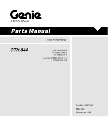
AT A GLANCESWING DOORDOOR HINGE PLATEMERCHANDISING GLASSWINDOWPULL-OUT DOORBACK-LIT POS CUSTOMGRAPHIC (OPTION)BILLVALIDATORSLOTACCENT DOWN LIGHTING(CHOICE OF COLORS)COIN ENTRY BEZEL (LIT)KEYPAD/3.5” COLOR DISPLAYOR10” CAPACITIVE TOUCH SCREENCASHLESS PAYMENT SLOTPRODUCT DELIVERY DOORFLAPCOIN RETURN/CHANGECUP/DOORDÉCOR PANELS (4)SILVER COLORSNAP-ON LEGTREATMENT/COVERDOOR HINGE PLATEADJUSTABLE LEGLEVELLER3605 360664225133 Rev C
UNPACKINGThis vendor was thoroughly inspected before leaving the factory and the delivering carrier has accepted this vendor as theirresponsibility. Please note any damage to packaging and/or machine at the time of delivery and report them to the carrier. Requesta written inspection report from the claims inspector to file any claim for damage. File the claim with the carrier within 7 days afterreceipt of the vending vendor.Carefully remove the outside packing material so as not to damage the finish or exterior of the vending vendor. Inspect the vendingvendor for concealed shipping damage. Immediately report any damage hidden by the shipping material directly to the deliveringcarrier on a hidden damage report.Record the model number and serial number of the vendor for your records. These numbers can be found on the serial plates onthe rear of the cabinet and/or inside the vendor. Referto these numbers in all correspondence and inquiriespertaining to this vendor.To remove the 2-wooden skid boards use a chisel orsmall crow bar to split the partly cut boards at thefront/Rear, see Fig 1a. Then turn the leveling screws inas far as possible prior to final placement.The leg covers can be found in the delivery bin. Installthese once the vendor has been placed on location andleveled, see Fig 1b).Fig 1b. Fit Leg CoversFig 1a. Remove Skid BoardsINSTALLATION Consult local, state and federal codes and regulations before installing the vendor.Retrieve the keys to the vendor from the coin return cup.Open the ‘pull-out door’ and then the ‘swing door’ and remove all internal packing material.WARNING: Position and level the vendor prior to connecting vendor to power. All set up steps must be completedprior to prevent harm to the installer or vendor and to ensure correct operation.REMOVING THE SWING DOORThe vendor will fit through most doorways (34" ) by opening the ‘swing door’ and carefullywalking the vendor door or cabinet through first and then moving the remaining portion ofthe vendor through.The vendor ‘swing door’ may be removed to permit easier movement through a narrower dooropenings or hallways. To remove the ‘swing door’:1. Disconnect Cabinet to Door harness: Cut the nylon tie strain relieving the harness to side of delivery bin Unplug the connector as shown in Fig 2.2. Remove the ‘Swing Door’:CAUTION: This requires two people.First mark an outline around the top hinge plate with a pencil to be sure the hinge is setFig 2. Disconnect Harness Plugback into the same position. Open the door at least 90 degrees and remove the (3)Carriage Bolts by undoing the nuts with a deep 1/2” socket, these fasten the top hinge plate to the cabinet top as shown inFig 3.Once the bolts are removed the door needs to be lifted vertically off the bottom hinge, see Fig 4.NOTE: The bottom hinge pin rests on top of (2) nylon washers to provide proper door height and smooth operation; thesewashers must be retained for reassembly.Fig 3. Remove Top Hinge Bolts3605 36067Fig 4. Lift Door off Hinge Pin4225133 Rev C
REMOVING THE PULL-OUT DOORIf it proves necessary to reduce the machine depth to approximately 31" the pull-out door can be removed as follows:1. Remove the (2) stop screws from the top and bottomslider channel as shown in Fig 5. Top Hinge:2. The Pull-Out Door can now be brought out further toprovide better access.NOTE: Ensure the 2 screws are replaced at the end ofthe procedure to prevent the slides being damagedFig 5. Remove the 2 Stop Screws3. Remove/disconnect the (8) ‘P’ Clamp and harness connections as shownin Fig 6.Feed all the cables down through the square hole in the base panel toenable the front assembly to be removed.Fig 6. Disconnect/remove harness/wires4. Remove and retain the (4) screws that connect the Coin mechanism panelto the 2 upright Tie Bars.Remove and retain the (2) screws that connect the support gusset to thefront Tie Bar as shown in Fig 7.Fig 7. Remove & retain these (6) Screws3605 360684225133 Rev C
REMOVING THE PULL-OUT DOOR . . . Contd.5. Remove the (4) screws from the top brace as shown in Fig 8Fig 8. Remove & retain these (4) screws6. Starting at the bottom, remove and retain the (3) screws fromeach of the (4) top & bottom slide rail both sides of the pull-outdoor, see Fig 9.Fig 9. Remove & retain the (3) screws from all 4Slide Rails7. The Pull-Out Door can now be dismounted from the (4) slide railsand pulled free as shown in Fig 10.Carefully move to a fee area and rest firmly against a solidupright out of ‘harm’s way’.Push the slide rails back in until they lock and continue tomaneuver the machine through the restriction.Reverse the above procedure/s to reassemble.Fig 10. Remove the (3) screws from all 4 Slide Rails3605 360694225133 Rev C
POWER CORDLoosen the (4) screws fixing the connection box cover, removethe cover and park on (2) screws as shown in Fig 11.The power cord and GFCI can be removed from its housing, thecover can then be replaced and secured.Keep the power cord secured on the center back of the cabinetuntil the vendor is placed into its final location to avoid damageto the cord.Fig 11. Loosen the (4) screws to Access the Power CordPOSITIONING & LEVELING VENDORPosition the vendor in its place of operation within 6 ft (183cm) from thepower outlet or receptacle. Check that the ‘swing door’ has clearance onthe left side to allow sufficiently to service/load the trays, see Fig 12.Leave at least 4” (10cm) inches between the back of vendor for aircirculation.All levelers must touch the floor. The vendor must be level for properoperation for the coins and to correctly align the ‘swing’ and pull-outdoors.Adjust the four (4) leg levelers on the cabinet legs to make the cabinetlevel front-to-back and left-to-right, use a spirit level or similar to verify.IMPORTANTGROUNDING (EARTHING) & ELECTRICALFig 12. Clearance for Loading Left SideConsult local, state, and federal codes and regulations before installing the vendor.Before connecting the vendor, the integrity of the main electrical supply must be checked forcorrect polarity, presence of ground (earth) and the correct voltage. These checks should berepeated at six-month intervals with the routine safety electrical testing of the vendor itself.If the receptacle is not properly grounded or polarized, contact a licensed electrician tocorrectly polarize and/or ground the receptacle to ensure safe operation.For proper operation of any equipment utilizing electronically controlled components, the equipment should be placed on adedicated, noise-free circuit and be properly polarized and grounded. Use of a surge conditioner/suppressor is recommended forlocations where electrical noise is present.MAIN POWER SWITCHPlug the power cord into the power outlet.Open the vendor ‘Pull-Out’ door and turn ON the main power switch located on the face of thepower panel within inside the cabinet, see Fig 13.Fig 13. Main Power Switch3605 3606104225133 Rev C
LOADING PRODUCTSLoad products from front to back making sure all items fit freely between the spiral spaces. Do not attempt to force oversize itemsor packages into the spiral spaces. Do not skip a space. Place the product on the bottom of the compartment on the product spiralson the tray floor and do not bridge across the spiral. The product label is to be facing the front of the vending vendor for easyidentification by the customer, see Fig 13.IMPORTANT: Some product packaging can cause the item to hang on the tray edge, in these cases it is recommended toinstall product pushers to assist with the ejection/release – part number 4226049 Product PusherGENERAL LOADINGTo load products, lift the tray slightly at front and pull forward until the tray stops. The trays willtilt once pulled forward for easier loading.The standing height of the item being vended must be taller than the diameter of the spiral beingused to vend correctly, see Fig 14.By re-timing the spirals, difficult-to-vend items can most times be dispensed more dependably.If the product does not fit the spiral properly i.e. if there is any interference, use a differentpitched spiral to provide more space. Call the number at the back of this manual for spiralsavailable from your distributor or service entity.Fig 14. Loading ProductsTRAY ADJUSTMENTS VERTICAL SPACINGBy altering the space between trays larger items can be vended. The trays can be adjustedup or down in half-inch increments to provide headroom for the products. When increasingthe height in one area, the same amount of room will be lost in the tray above or belowthe one being adjusted. See Fig 15.CANDY, SNACK AND 3/4 SNACK TRAY ADJUSTMENTSFig 15. Tray RailsFull SNACK5.75”(14.6cm)¾ SNACK4.312” (11cm)CANDY2.875”(7.3cm)All trays have adjustable divider locations. By adding, removing, or relocating dividerpositions a wide variety of selection compartment widths can be derived as required, seeFig 16. The dividers can be located in every ½ Candy position. This adjustment providesfor CANDY (candy bars, crackers), ¾ SNACK (small chip bags, cookies), and full sized SNACK(chips, pastries) compartment sizes. Adjustments can also be made for compartmentswider than a SNACK compartment width for larger/wider items. Every tray provides motorconnections for the maximum number of selections per tray. Additional parts (dividers,motors, spirals, and adapter kits) are available.Fig 16. Divider Positions and Approximate Sizes3605 3606114225133 Rev C
SPIRAL ADJUSTMENTThe shape, size and thickness of a product affect how well it isejected from the tray. Most products can be vended successfullywhen the spiral end is positioned at 7 or 5 o’clock as shown. Ifvending problems occur with spiral ends at the standardpositions, adjust the drop-off either by retiming the spiral orinstalling a Product Pusher.ADJUST SPIRALCOUNTERCLOCKWISE FORTHICKERPRODUCTSADJUST SPIRALCLOCKWISEFOR THINNERPRODUCTS(i.e. 7:00ADJUST SPIRAL END POSITION FOR SUCCESFULVEND.MOST PRODUCTS VEND PROPERLY AT EITHER7 OR 5 O'CLOCK AS SHOWN ABOVEEVOKE 6 TRAYSThe Evoke 6 employs a new steel powder coated tray and rail design which is stronger to tolerate the bigger trays and is servicefriendly.The rails for the bottom 2 trays employ a stop bracket which prevents these 2 trays from tilting which is more ergonomicallyfriendly for loading/filling, there is no need to tilt these trays down for filling. The upper trays will tilt down to facilitate filling.The illustrations below show the 2 tray rail types, tilting and non-tilting examples:TILTED DOWNNO TILTCAUTION: WHEN PULLING TRAYS OUT ENSURE TRAY IS HORIZONTAL, BEING CAREFUL NOT TO LIFT THE TRAY ATTHE FRONT TOO HIGH AS THIS COULD RELEASE THE TRAY FROM ITS RAILS AND IT COULD FALL OUT – SEE TRAYREMOVAL BELOWTRAY REMOVALTo remove a tray from the machine the electrical harness must first be disconnected. Then pull the tray forward and lift the frontof the tray to approx. 30 up from horizontal such that the side stop tab is above the release level as shown below, then pullforward and lift out of the machine:3605 3606124225133 Rev C
DUAL PINION GEARThe dual-spiral configuration utilizes a single motor and a pair of pinion gears, the motor pinion gear drives the idle paired gear.The idle pinion gear/spiral adaptor is snapped into its retainer and held in place by the housing as shown below.The pairs of gears/spirals are staggered across the tray, each pair being either in front or behind the adjacent pair. The pinion gearcan be installed with a smaller or larger spacing from the back of the tray by flipping it around 180 . This ensures that the pairs ofpinion gears do not engage with each other, see below:SMALLERSPACING3605 3606LARGERSPACING134225133 Rev C
DUAL PINION GEAR . . . . Contd.The illustration below shows the adjacent pairs of pinion gears offest rearward/forwardThe spiral/adaptors and its pinion gears can be meshed together such that the ends of the spirals are mirrored in position to ensurethe spirals push the item to be vended evenly and consistently.DOOR SWITCHThe door switch is located on top of the Pull-Out Door slide housing, see Fig 17.The door switch is monitored by the FLEX control system, when the pull-Out Door is opened the display will show and errors thatmay have been logged. To reset the errors displayed press the # key.Fig 17. Door Switch3605 3606144225133 Rev C
SERVICE MODEUse the Service Mode to program and service the vendor. Use the keypad as an input device. Observe the display for informationwhile in Service Mode.SERVICE MODE BUTTONTo enter Service Mode, press the Service Mode Button once, it islocated in the bottom left hand corner of the control board, see Fig 18.To exit Service Mode, press the Service Mode Button again once or pressthe * key 3 times.NOTE: If no key is pressed for approximately one minute while inService Mode, the controller will automatically return to Sales Mode.POWERFor all programming features and functions please refer to the4225134 Programming Manual which can be found and/ordownloaded from http://www.vendnetusa.com/Manuals/Snack.Fig 18. Service Mode ButtonMOTOR PAIRINGThe ‘motor pairing’ feature facilitates the ganging together of 2 individual motors, so that when a single selection code is enteredboth motors will operate together; the LH motor will rotate CCW and the RH motor will rotate CW, the corresponding spirals alsohave to be CCW & CW.This feature allows the 2 motors to be spread apart from each other to suit the width of the item to be vended. The selection widthcan be as little as 5 ¾“ (14.6cm) or the paired motors/spirals can span the entire width of the shelf e.g. ganging selection motors40 & 49.The 2 ‘paired motors’ have to be wired to suit the physical span between them, this will determine the selection numbers to bepaired.See the 4225134 Programming Manual for instructions to set-up ‘paired motors’.3605 3606154225133 Rev C
INSTALLING A COIN CHANGER1.Mount the changer unit onto the 3 screws provided and then secure, See Fig 19.2.Check the alignment between the underside of coin entry chute and top of entry hopper,adjust chute so there is only 1/8” (3mm) clearance.3.With the machine switched ON press the coin return button to check the operation of thecoin return. Ensure that the reject lever on the coin mechanism is actuated sufficiently bythe motor cam to clear bent coins, adjust by slackening the screws securing the coin returnmotor bracket and adjusting up/down; retighten the screws when complete.4.The Coin Changer must be loaded with some coins in each tube for the vendor to operateproperly and allow the bill validator to accept most bill denominations, a minimum of 50% isrecommended.5.To fill the coin tube first press the Service Mode button on the control board, then there willbe no restriction on the amount of coins that can be accepted. When exiting service modeany credit is cleared to zero.Fig 19. Payment SystemsCASH BOXTo remove the cash box lift it vertically upwards to release the shouldered bushes from the keyholemounting slots at the back of the box, then pull forward to release, see Fig 20. When returning thecash box align the shouldered bushes with the keyholes in the rear mounting plate pushed and allowthe cash box to sit down.IMPORTANT:1. Ensure that the cash box is in position before closing the pull-out doorFig 20. Cash Box3605 3606164225133 Rev C
BILL VALIDATOR OPERATION (OPTIONAL)To remove the bills from the BillValidator push the tab on the top ofthe bill box and lift up. To clear jamsor cleaning unlatch lower unit asshown. Dollar Bill Validator cleaninginstructions as well as moreadvanced service information can beobtained on the Service portion ofthe website listed at the end of thismanual.IVEND OPTICAL SENSINGAll selections have been assigned at the factory to be monitored for iVend optical sensing. At the start of a vend, the iVend optical sensor will be checked to make sure it is not blocked, damaged or disconnected.If iVend is blocked, damaged or disconnected the system can be configured to react in one of 2 programmable ways i) to operatewith a single turn of the vend motor and credit will be taken regardless or ii) the machine will be rendered out of service.When iVend is operating normally the vend motor and a vend timeout timer are started, the selection motor/s rotate/s a full turn(360 ) to the home-switch position, if a product is detected dropping into the delivery bin the vend is considered successful.However, if the home-switch position is reached and a product has not been detected, then the vend motor will pause for 1 secondwhile the controller continues to monitor the optical sensor for product delivery and then If a product is detected during this pausethe vend is considered successful. If a product is not detected, then the controller initiates a second motor cycle while continuingto monitor the optical sensor.If a product is detected during this second cycle, the motor will be stopped immediately. The vend is considered successful. The2ND VEND accounting counter is increased by one.If after reaching the home-switch position and a product has not been detected, then the vend motor is stopped and for 2 secondsthe controller continues to monitor the optical sensor for product delivery. If a product is detected, the vend is consideredsuccessful. The 2ND VEND accounting counter is increased by one.If no product is detected, the selection is logged as ‘sold out’. Such a state will trigger to displaythe MAKE ANOTHER SELECTION message. The original credit remains and is displayed, the customer can press selection buttons toactivate this or another motor or press the coin return button.DISPLAY CREDIT - ELECTRONIC PRICINGThis vendor is equipped with Electronic Pricing, the customer may verify the price by pressing the selection number before insertingmoney. If a selection is made and credit has not been established, the price for that selection is displayed and the customer isprompted “INSERT MONEY”. When money or credit is accepted, then the amount of credit is displayed/confirmed."USE EXACT CHANGE ONLY" MESSAGE OPERATIONIf the coin levels in the coin mechanism tubes are below the low-level sensors, “USE EXACT CHANGE ONLY” will be displayed. Thisindicates the Coin Changer does not have enough coins in the coin change tubes to make/return change. This also indicates thatthe Dollar Bill Validator may be disabled until change can be made.3605 3606174225133 Rev C
PREVENTIVE MAINTENANCECAUTION:Always disconnect power source BEFORE cleaning or servicing.IMPORTANT:To ensure the vendor delivers its max
3605 3606 4 4225133 Rev C SAFETY WARNINGS & SPEIFIATIONS DIMENSIONS & WEIGHTS MANUAL REVISION HISTORY TYPE 3605 - 5 Wide 3606 - 6 Wide REV DATE REASON MODEL 3605/3605A 3606/3606A A 01/31/2017 Initial release WIDTH 41" (104cm) 45" (114.3 cm) B 11/01/2018 DEPTH 35.2" (89.4cm) 35.2" (89.4cm) C 05/18/2019 Evoke 6 tray content added