Transcription
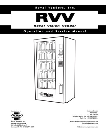
RoyalVendors,Inc.RVVRoyal Vision VenderVeOperationManufactured byandServiceManualCustomer Service:800 931 9214 1 304 728 7056Technical Service Fax: 1 304 725 6579Parts Fax: 1 304 725 4016RRoyal Vendors, Inc.Bardane Industrial Park426 Industrial BoulevardKearneysville WV 25430-2776 USARoyal Vision VenderE-mail: s.comWebsite: www.royalvendors.comPage 1
Royal Vendors, Inc. 426 Industrial Boulevard Kearneysville WV 25430-2776 USACustomer Service: 1 (304) 728-7056 or Toll Free (800) 931-9214 Fax (304) 725-6579E-mail: s.comWebsite: www.royalvendors.comPage 2Royal Vision Vender
TABLE OF CONTENTSSAFETY SEGMENT . 5SECTION 1: General Information and Setup . 7Introduction . 7Unpacking the Vender and Installing It On Location . 7Voltage Requirements and Vender’s Power Cord . 8Setting Up the Cells. 8Programming the Vender . 8Specifications . 8Warranty Information . 9Important Note on Transporting the RVV . 9Vender Identification . 9SECTION 2: Vender Component Explanation . 10Vender Control Board (including pinouts) . 10Keypad . 13Delivery Sensor . 13Door Switch . 13Vacuum Fluorescent Display (VFD) . 13Low-Voltage Transformer . 13Product Shelves . 14Refrigeration System . 14Ballast . 16Credit Peripherals . 16TriTeq Electronic Door Lock. 16SECTION 3: Vender Programming. 17Internal (Service) Menu . 18Errors Were Detected (or No Errors Found) . 18Coin Dispense / Insert . 20Diagnostics. 20Cash Collected . 21Number of Vends . 21Free Vend Count. 22Set Prices . 22Product Location . 22Space to Sales . 23Set Configuration . 24Door Password . 25Lighting . 26Royal Vision VenderPage 3
TABLE OF CONTENTS (Continued)Set Refrigeration . 27Set Internal Clock . 29Set Language . 29Set Block 1 / 2 / 3 . 30Discount. 31Override Options . 33Return . 34SECTION 4: Vender Maintenance . 35What to Clean . 35What to Lubricate . 35Preventive Maintenance . 35Replacing the Belts . 36Product Location Setup Procedure . 38SECTION 5: Troubleshooting . 40SECTION 6: Parts Catalog . 44RVV Control Board . 44Door Assembly, Rear . 46Door Assembly, Front . 48Port Assembly . 49Elevator Mechanism . 50Narrow Elevator Cup Assembly . 52Elevator Cup Assembly . 53Lower Drive Subassembly . 54Port Door & Slide Assembly RVV . 55Security Plate Assembly RVV, T-handle Lock. 56Security Plate Assembly RVV, TriTeq Lock . 57Cell Assembly RVV . 58Shelf Assembly RVV . 60Evaporator Section . 61Cabinet . 62SECTION 7: Wiring Schematic . 64SECTION 8: Programming Flowchart . 65CREDIT AND REPLACEMENT POLICY . Back CoverPage 4Royal Vision Vender
SAFETY SEGMENTROYAL VENDORS’COMMITMENT TO SAFETYRoyal Vendors is committed to safety with all ofour product designs. We are committed tonotifying the user of a possible danger involvingthe improper handling or maintenance of ourvenders. The servicing of any electrical ormechanical device involves potential dangers,both to those servicing the equipment and tousers of the equipment. These dangers can occurbecause of improper maintenance or usage. Thepurpose of this safety segment is to alert everyone servicing Royal equipment of potentiallydangerous areas, and to provide basic safetyguidelines for proper upkeep.The service manual contains various warningsthat should be carefully read to minimize the riskof personal injury. This manual also containsservice information to insure that proper methodsare followed to avoid damaging the vender ormaking it unsafe. It is also important to understand these warnings provide general guidanceonly. Royal could not possibly know, evaluate, oradvise of all of the conceivable ways in whichservice might be done. Consequently, Royalcannot predict all of the possible dangerousresults. These outlined safety precautions are thebasis for an effective safety program. Use thesesafety measures, along with the service bulletins,helpful hints and product specification sheets,when installing or servicing Royal equipment.We recommend that persons servicing ourequipment maintain a similar commitment tosafety. Only personnel properly trained shouldhave access to the interior of the vender. This willminimize the potential dangers that are inherent inelectrical and mechanical devices. Royal has nocontrol over the vender once it leaves thepremises. It is the owner or lessor’s responsibilityto maintain the vender in a safe condition. Seeinstallation insert located in the coin box of a newvender for proper installation procedures and referto the service manual for recommended maintenance procedures. If you have any questions,please contact the Technical Services Departmentat 1.800.931.9214.Royal Vision VenderSAFETY REGULATIONS·········Read the safety segment before installation orservice.Test for proper grounding before installing toreduce the risk of electrical shock and fire.Turn off or disconnect power cord from walloutlet before servicing.Only fully trained service technicians shouldservice vender when vender has power.Remove any product before moving a vender.Use appropriate equipment when moving avender.Always wear eye protection, and protect yourhands, face, and body when working near therefrigeration system.Use only authorized replacement parts.Be aware of inherent dangers in rocking ortipping a vender.SECTION I: ELECTRICALHAZARDS GENERAL ADVICECareless or improper handling of electrical circuitscan result in injury or death. Anyone installing,repairing, loading, opening, or otherwise servicinga vender should be aware of this precaution.Apply all of the normal precautions when handlingelectrical circuits, such as:· Refrigeration servicing to be performed byqualified personnel only.· Unplug the vender before servicing· Replace electrical cords if there is anyevidence of fraying or other damage.· Keep all protective covers and ground wiresin place.· Plug equipment into outlets that are properlygrounded and polarized (where applicable),and protected with fuses or circuit breakers ofthe correct size.· All electrical connections must be dry and freeof moisture before applying power.WARNING:ALWAYS TEST TO VERIFY PROPER GROUNDING PRIOR TO INSTALLATION IN ORDER TOREDUCE THE RISK OF ELECTRICAL SHOCKAND FIREPage 5
SAFETY SEGMENTSECTION II: ELECTRICALHAZARDSA. Servicing with “Power Off”For maximum safety, unplug the power cord from thewall outlet before opening the vender door. This willremove power from the equipment and avoidelectrical hazards. Service personnel should remainaware of possible hazards from hot componentsalthough electrical power is off.B. Servicing with “Power On”Some service situations may require access withpower on. Only fully qualified service techniciansshould perform power-on servicing. Particularcaution is required in servicing assemblies thatcombine electrical power and mechanical movement.Sudden movement (to escape mechanical action)can result in contact with live circuits and viceversa. It is therefore important to maintain maximumclearances from both moving parts and live circuitswhen servicing.WARNINGS:1. ONLY FULLY TRAINED PERSONNEL SHOULDACCOMPLISH “POWER-ON” SERVICING.SUCH SERVICE BY UNQUALIFIED INDIVIDUALS CAN BE DANGEROUS.2. LIGHTING CIRCUITS CAN BE HAZARDOUS.ALWAYS DISCONNECT FROM POWER SUPPLYBEFORE REPLACING A BULB OR SERVICING THEVENDER IN THAT AREA.3. NEVER USE A HOSE, PRESSURE WASHER ORANY CLEANING METHOD THAT COULD WETELECTRICAL COMPONENTS. SEE CLEANINGSECTION OF MANUAL FOR SUGGESTEDCLEANING METHODS. IF WATER CONTAMINATION OF ELECTRICAL COMPONENTS IS SUSPECTED, USE QUALIFIED ELECTRICAL TESTINGEQUIPMENT AND TEST METHODS TO ASSURETHAT VENDER IS NOT A HAZARD BEFOREAPPLYING POWER FOR ANY REASON.Page 6Royal Vision Vender
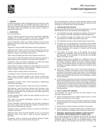
SECTION 1: General Information and SetupREMOVE THE INTERIOR PACKINGGeneral InformationIntroductionThis manual contains installation, operation, and serviceinstructions for the Royal Vision Vender (RVV), by RoyalVendors, Inc. This manual also contains a complete partscatalog and electrical schematic for the RVV.The RVV is a microprocessor-controlled glass-front venderthat permits pricing per selection from 0.00 to 99.99. TheRVV provides electronic space-to-sales programmability,and it will collect, store, and transfer MIS data fields to ahand-held computer (HHC) or on-line device through aDEX port.Unpacking the Vender andInstalling It On LocationUNWRAP THE VENDERUnwrap the vender and remove the padding. Check forany signs of damage. If the vender is damaged, contact thecarrier immediately. They will instruct you on the procedure for filing a claim.If the vender is being stored, remove the plastic stretchwrap, cardboard cover, and styrofoam cushioning first.The plastic stretch wrap and styrofoam cushioning canadhere to the exterior of the vender over an extendedperiod of time, damaging the vender’s finish.Before plugging in the vender’s power cord, remove theinterior packing. Failure to remove this packing beforeplugging in the vender could result in damage to the vendmechanisms. Remove the styrofoam blocks in the front of each cell,which are used to secure the pushers. Remove the packing tape which secures the casesupports. Remove the binder clips that secure each of the twobelts, located approximately in the middle of the belts’runs. Remove the styrofoam block located below the elevatorarm, above the motor cover.PLACING THE VENDER ON LOCATIONWhen placing the vender on location, allow for a minimumof four inches (4”) of space at the back of the vender. Thiswill ensure proper ventilation of the refrigeration system.To level the vender, close and latch the vender’s door.Using a spirit level, adjust the four leveling legs until thetop of the vender is level left-to-right and front-to-back.Make sure all leveling legs are in contact with the floor(including the support leg - see below).ADJUSTING THE SUPPORT LEG (Serialnumber 200412MA00005 and after only)The RVV is equipped with a support leg that is designed toprevent the vender from tipping. Always ensure that thisleg is extended all the way to ground level. Failure to do somay result in the vender tipping forward, potentiallyresulting in broken bones, dismemberment, or even death!The support leg is located under the bottom hinge plate ofthe vender’s main door. Using a 1½” (38 mm) wrench, turnthe leg counterclockwise until it is extended to groundlevel.Note: The vender’s keys are located in the coin cup.REMOVE THE SHIPPING SKIDSeparate (split) each section of the shipping skid byinserting a claw hammer, crowbar, or similar device into theslot of each section to break it apart. Tilt the venderslightly to remove the separated pieces. (See Figure 1.1.)REMOVE DOOR BLOCKAfter opening the vender’s door, locate the woodenshipping block at the bottom right under the door. Lift theblock straight up to remove it.Figure 1.1Royal Vision VenderPage 7
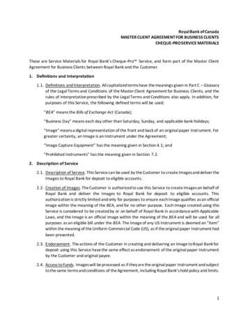
SECTION 1: General Information and SetupVoltage Requirements andVender’s Power CordThe vender is designed to operate at a voltage of 115 voltsAC, 60 Hertz. It requires the minimum of a 15 amp service,and it should be on a dedicated circuit. The service outletvoltage must not exceed 129 VAC or fall below 103 VAC.The vender has a three-wire grounding cord. The vendermust be plugged into a grounded electrical outlet to protectcustomers from electrical shock. If the outlet is notequipped with a grounded socket, have one installed by aqualified electrician. Do not use an extension cord, unlessit has been authorized by a certified electrician. Extensioncords are not recommended.After plugging the vender’s power cord into the ACvoltage source, the following should be observed:1.2.3.The fluorescent lights will come on;The refrigeration compressor will start to run afterapproximately 5-7 minutes (with the door closed); andThe Vacuum Fluorescent Display will light.The control board is equipped with a battery back-up foruse in the event of a power loss. The battery is used toretain important programming information, such as spaceto-sales, prices, etc., so that it will not be erased if power islost or the vender is unplugged.Setting Up the CellsThe cells must be set up correctly in order to ensurereliable vending. Note: Some packages may requireslightly different adjustments depending on the location ofmanufacture of the package.CELL SETUP INSTRUCTIONS:1. Serial number 200412MA00005 and after: Unlockthe cell by sliding the cell locking mechanism all theway to the left. Push the cell to the right slightly, andpull it out about 6 to 8 inches (15 - 20 cm).Prior to serial number 200412MA00005: Place theshelf locking mechanism in the correct position for theshelf which holds the cell to be adjusted. (See Figure1.3.) Then, slide the cell locking mechanism all theway to the left. Lift the product cell straight up, andpull it out about 6 to 8 inches (15 - 20 cm).2. Loosen the wing nut on the bottom of the cell thatsecures the cell wall.3. Push down on the strap locking mechanisms of thecenter support assembly.4. Move the cell wall inward or outward to the desiredsetting, using the cell setup decals as a guide.5. Once the cell is at the correct setting, release the straplocking mechanism.6. Tighten the nut on the bottom of the cell to secure thecell wall in position.7. Push the cell back into place, and lock the shelf.Programming the VenderCell locking mechanismAll programming of the vender is done in the ServiceMode. To enter the Service Mode, open the vender’s maindoor, and press and release the Service Mode Button,located on the controller board. For programming instructions, see the section entitled “Vender Programming,” laterin this book.SpecificationsDimensions (280 cap.) . 72”H x 37”W x 35.5”DApproximate Empty Weight . 760 lbs.Operating Voltage . 115 VAC, 60 HzAmperage Rating . 12 AmpCharge . 8.0 oz. R134aConstruction . Steel cabinet, plasticcells, glass frontConfiguration . 5 shelves, 40 columnsFigure 1.2Page 8Royal Vision Vender
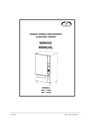
SECTION 1: General Information and SetupWARRANTY INFORMATION IMPORTANT NOTE ONTRANSPORTING THE RVVRoyal Vendors, Inc. warrants (to the original purchaser)vend motors and product cells for five years and threemonths. The warranty of the refrigeration system, consisting of the motor, compressor, evaporator, “clean-flo”condenser, and the refrigerant tubing, will be for five yearsand three months, and will follow the serial number on theoriginal cooling unit. If the unit fails while under warranty,the same serial number will be put on the replacement unitto track warranty status. Any unauthorized tampering withor cutting (tapping) into the unit will void the warranty.The control board, touch pad, vacuum fluorescent display,and Precision Delivery System are all warranted for threeyears. All other parts, except the light bulbs and finish, arewarranted for one year.Notes:1. Do not use the vender serial number for the coolingdeck and control board. These parts carry their ownwarranty.2. All stock refrigeration units and control boards willbe labelled with a date code (the date the part wasshipped to the customer).Royal Vendors’ obligation under warranty is limited torepairing or replacing the subject part at our discretion,when upon examination it was determined by RoyalVendors to be defective. Royal Vendors will pay shippingcharges on all parts covered under this warranty whentransportation has been made the most economical way.The warranty is voided when a cabinet or any part thereofhas been subject to misuse or alteration without properauthorization. Accident or damage caused by fire, flood,transportation, civil disorder, or acts of God are notcovered under warranty.All shelves lockedFirst (top) shelf unlockedSecond shelf unlockedThird shelf unlockedFourth shelf unlockedFifth (bottom) shelf unlockedBefore transporting the RVV, always ensure that theprotective transport packaging is replaced, including: Styrofoam blocks in the front of all cells, to secure thepushers; Styrofoam blocks on the cell locking mechanism lever; Packing tape to secure the case support; Styrofoam block on top of the motor cover, below theelevator arm; Binder clips to secure each belt, placed approximately inthe middle of each belt’s run; and Cardboard to protect the glass.Improper packaging before shipping could cause damage.Vender IdentificationVENDER SERIAL PLATE — The vender’s main serial plateis loacted on the exterior left side of the vender’s main doorand has the following information: Vender model codeVender serial numberAmps required by the venderUnit charge of R134aRefrigeration design pressuresThe vender’s model code contains useful information: themachine type, such as RVRVV (Royal Vendors Royal VisionVender); the model number, such as 400; and the number 1,which designates that the vender has a keypad.The vender’s serial number contains several importantpieces of information as well. The serial number currentlyin use consists of the following: The first four numbers represent the year the venderwas produced; The fifth and sixth digits represent the week within thatyear the vender was produced; The first letter represents the style of the vender; The second letter represents the location where thevender was built; and The last five digits represent the number of that venderbuilt within that week.REFRIGERATION SERIAL PLATE: The RefrigerationSerial Plate is located on the front of the vender’s refrigeration unit, mounted on the kick plate. It looks similar to theVender Serial Plate with the exception that the modelnumber specified is the refrigeration unit model. There iscurrently one model in use:Model8000VCompressor sizeSuper 1/3 HorsepowerUsageAll RVVFigure 1.3Royal Vision VenderPage 9
SECTION 2: Vender Component ExplanationVender ComponentExplanationVender Control Board(including pinouts)The control board is responsible for most vender operations. It is located in the upper left corner of the inside ofthe door. The control board is protected by a cover.Removing this cover will expose the control board, alongwith all wiring connections to the board.IDENTIFICATION: The RVV control board can be easilyidentified by noting the software revision number printedon the board in white letters in the upper-right corner.OPERATION REQUIREMENTS: The control boardrequires approximately 24 volts AC from the low-voltagetransformer. This will allow the control board to functionand to supply power to all the vender’s components listedbelow.OPERATION: Upon receiving the appropriate voltage fromthe transformer, the control board issues information tosome components, receives information from somecomponents, and communicates both ways with somecomponents. The control board issues instructions (and / orvoltage) to:Vacuum Fluorescent Display (VFD)Vend mechanismsRelays (refrigeration, evaporator, andlights)CONTROL BOARD PINOUTS: The RVV has severalelectrical pinouts, a set-up mode button, and various otherelectronic components (all of which have designatedposition codes). The following section outlines all thecontrol board’s pinouts.The word key refers to the small plastic insert plugged intoa position of the connector. The purpose of the key is toprevent connecting the harnessing backwards or upsidedown. The “keyed position” is a blank position within thepinout (no pin) in which a key is inserted. Some pinoutsmay have several blank positions with a key plugged intoone or more of the positions. You can use the key todetermine which end of the pinout is Pin 1.Temperature Sensors (Position P1): The wiring harnessconnected to this pinout travels from the temperaturesensor to the control board. This harness is molded intothe temperature sensor and should never be cut, pinched,or spliced together if cut. If the harness is cut, pinched, orimproperly grounded, the sensor may give the controlboard false temperature iteRedBlackWhiteRedFUNCTIONGroundHealth Sensor signalHealth Sensor groundHealth Sensor signal groundTemperature signalTemp. sensor groundTemp. signal ground The control board receives information (and / orvoltage) from:Keypad (logic level)Door switch (logic level)Delivery sensorTemperature sensor The control board communicates both wayswith:Coin mechanismBill validator (optional)Card reader (optional)Hand-held computer (optional)Page 10Royal Vision Vender
SECTION 2: Vender Component ExplanationRefrigeration (Position P2): The wiring harness connecting to this pinout powers the refrigeration relay. It alsosends power to the door switch and to the delivery switch.The board powers the relay by providing a constant 24VDC to it. Upon activation, the control board also provides a neutral to the relay. For the door switch and thedelivery switch, the board provides a constant 5 VDC.When the switches are pressed in, they complete a circuitto the control reenBlue-FUNCTIONDelivery switch return5 VDC door switchDoor switch returnnot used24 VDC refrigeration relayRefrigeration relaynot usednot usednot usednot usedSelection Switches (Position P3): This pinout is notcurrently used.Electronic Keypad (Position P3b): The RVV uses a keypad,which utilizes a matrix wiring system. Upon pressing aparticular button, a signal circuit is completed. Becauseeach output wire carries a different signal, the controllerwill determine which key has been pressed based on whichinput wire receives the output yal Vision VenderFUNCTION24 VAC24 VACGround5 VDC VCCCO1CO2CO3CO4not usednot usedRW2RW3RW4not usedDelivery Sensor (Position P4): The harness connecting tothis pinout should never be cut, pinched, or spliced if cut.The delivery sensors are located in the port area of thevender’s main door. The emitter is located above the port;the receiver is located below the livery sensor powerKeyDelivery detection signalGroundX-Axis (Position P5): The X-axis is the left and rightmovement of the product eenVioletGreyFUNCTIONX-axis Phase AKeyX-axis Phase BX-axis Phase CX-axis Phase DHome signalHome switch returnY-Axis (Position P6): The Y-axis is the up and downmovement of the product iteVioletGreyFUNCTIONY-axis Phase AY-axis Phase BY-axis Phase CKeyY-axis Phase DHome signalHome switch returnPage 11
SECTION 2: Vender Component ExplanationZ-Axis (Position P7): This harness is for the delivery doorswitch. The delivery door switch signals to the controlboard when the port slide door is UNCTIONnot usednot usednot usednot usednot used5 VDC sliding port door switchnot usednot usedReturn sliding port door switchnot usednot usedMulti-Drop Bus (Position P8): The five-wire serial harnessconnecting to this pinout provides power and communications to and from the control board for the coin mechanism,the optional 34 VDC bill validator, and/or the optional debitcard reader. If this harness is cut, pinched, or disconnected, you will noticeably lose power to these Yellow-FUNCTION34 VDCReturnKeyReceiveTransmitCommonKeyDEX / UCS (Position P9): The optional three-wire harnessconnecting to this pinout comes from the optional HandHeld Computer (HHC) jack. (Note: There is also astandard DEX / UCS jack located on the vender’s controlboard at Position P9A.) The HHC plugs into this jack toread and write information from the vender’s control board.If the HHC is not operating properly, check this harness forbad connections at the solder joints. Also check to ensurethe insulator is not cracked from over tightening.PINNUMBER1234Page 12WIRECOLORBlackRedBrownFUNCTIONCommon (sleeve)Receive (ring)KeyTransmit (tip)Display (Position P10): This pinout is not currently used.Display (Position JP1): The harness from this connectionleads to the Vacuum Fluorescent Display. If the displaydoes not work, check this connection and UNCTION5 VDCClockDataGround24 VAC Power (Position P11): The three-wire harnessconnecting to this pinout comes from the low-voltagetransformer. If this harness is not connected (or if power islost to this connection), you will noticeably lose all venderfunctions (except main door lighting), including power tothe Vacuum Fluorescent Display. The coin mechanism willnot accept coins, and the refrigeration system will not 4 VACNeutralKeyGroundEncoders (Position P14): The motor encoders, for the Xaxis and Y-axis stepper motors, ensure that the motors haverun the correct distance to reach a certain point. If the Xaxis (left and right motion of the elevator cup) or Y-axis (upand down movement of the elevator arm) are incorrect,check the harness leading to this connection. Note: Theencoder is part of the motor assembly and cannot beremoved e / Orange 5 VDC Y-axisGreyX-axis forward messagePinkX-axis backward messageWhite / Pink Y-axis backward messageWhite / Grey Y-axis forward messageKeyOrange5 VDC X-axisVioletGround X-axisWhite / Violet Ground Y-axisRoyal Vision Vender
SECTION 2: Vender Component ExplanationElectronic Door Lock (Position P15): Some venders maybe equipped with an electronic door lock system. In theevent of a power loss to t
Royal Vision Vender Page 1 Royal Vendors, Inc. Operation and Service Manual RVV Royal Vision Vender Customer Service: 800 931 9214 1 304 728 7056 Technical Service Fax: 1 304 725 6579 Parts Fax: 1 304 725 4016 E-mail: technicalinquiry@royalvendors.com parts@royalvendors.com Website: www.royalvendors.com R Manufactured by Royal Vendors, Inc.