Transcription
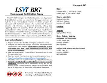
HEAVY MOVABLE STRUCTURES, INC.12TH BIENNIAL SYMPOSIUMNovember 3-6, 2008Rehabilitation of the Fremont Bridge inSeattle, WashingtonJohn Williams, P.E.Stafford Bandlow Engineering, Inc.CARIBE ROYALEORLANDO, FLORIDA
Rehabilitation of theFremont Bridge inSeattle, WashingtonINTRODUCTIONConstruction of the Fremont Bridge, 1916 Seattle Municipal Archives Photograph CollectionThe Lake Washington Ship Canal, which runs through Seattle, Washington connecting LakeWashington to Puget Sound, is a system consisting of, from east to west, Union Bay, theMontlake Cut, Portage Bay, Lake Union, the Fremont Cut, Salmon Bay, the Hiram M.Chittenden Locks, and Shilshole Bay. Started in 1911, the canal was officially completed in1934, though the Locks had opened 17 years earlier.The Canal's crossings, from east to west, are: The Montlake Bridge carrying Montlake Boulevard over the Montlake Cut The University Bridge carrying Eastlake Avenue over Portage Bay The Ship Canal Bridge carrying Interstate 5 over Portage Bay The George Washington Memorial Bridge (commonly called the Aurora Bridge) carryingAurora Avenue N. (State Route 99) over the west end of Lake Union The Fremont Bridge connecting 4th Avenue N. to Fremont Avenue N. over the FremontCut The Ballard Bridge carrying 15th Avenue over Salmon Bay The BNSF Railway's Salmon Bay Bridge over Salmon BayThe Fremont, University, Ballard and Montlake bridges are all Chicago style, trunnion basculebridges designed and built by the City of Seattle from 1916-1925. The Fremont Bridge wasopened on Friday June 15, 1917 at a cost of 410,000.HEAVY MOVABLE STRUCTURES, INC.th12 Biennial Movable Bridge Symposium
Rehabilitation of theFremont Bridge inSeattle, WashingtonFremont Bridge, circa 1917 Seattle Municipal Archives Photograph CollectionFremont Bridge, 1936 during re-decking Seattle Municipal Archives Photograph CollectionHEAVY MOVABLE STRUCTURES, INC.th12 Biennial Movable Bridge Symposium
Rehabilitation of theFremont Bridge inSeattle, WashingtonAll four of these bridges are still in operation today, although ownership of the Montlake Bridgehas been transferred to the Washington State Department of Transportation. Of the movablebridges, the Fremont bridge has the lowest clearance (30’) from the water. As a consequence,the opening frequency is the highest. According to the City of Seattle, the Fremont Bridgecurrently opens an average of 35 times per day or almost 13,000 times per year, making it one ofthe busiest movable bridges in the world despite being closed to water traffic during rush hours.The Fremont Bridge celebrated its’ 566,000th opening in January.In the mid 1980’s, the City undertook a program to rehabilitate and modernize the structural,mechanical and electrical systems of the three remaining, City owned movable bridges. StaffordBandlow Engineering (SBE) was retained as a sub consultant to provide the mechanical designfor the rehabilitation of all three bridges. Sverdrup Civil was the Prime Consultant for therehabilitation of the University and Ballard bridges. Parsons Brinckerhoff was the PrimeConsultant for the rehabilitation of the Fremont Bridge.Rehabilitation of the University Bridge was completed in 1988. Due to funding limitations, therehabilitation of the Ballard and Fremont bridges was delayed, and in the case of the BallardBridge, was completed in phases. The mechanical and electrical rehabilitation of the BallardBridge was completed in 2001. The rehabilitation of the Fremont Bridge, including replacementof the approach spans, began in September 2005 and was completed in 2008.Fremont Bridge original span drive machinery, 1936 Seattle Municipal ArchivesPhotograph CollectionHEAVY MOVABLE STRUCTURES, INC.th12 Biennial Movable Bridge Symposium
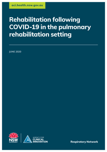
Rehabilitation of theFremont Bridge inSeattle, WashingtonTemporary Span Drive MachineryAll three of the movable brides over the Lake Washington Ship Canal are heavily used byvehicles, pedestrians, bicycles and marine vessels. Maintaining operation of the bridges for allof the users during a major rehabilitation project was a priority. In order to maintain operation ofboth movable leaves during the replacement of the span drive machinery, a temporary span driveoperating system would need to be utilized. A temporary winch operating system was selectedfor use on the basis of simplicity, low cost, and the flexibility of the system to be used during therehabilitation all three of the City’s bascule bridges.Elevation of the Temporary Winch Span Drive Operating Machinery arrangement.The system designed by SBE was built for use on the University Bridge rehabilitation, loaned toMultnomah County, Oregon for use during a rehabilitation of the Broadway Bridge in the 90’s.The system was returned to Seattle and used at the Ballard Bridge rehabilitation before utilizingit for the Fremont rehabilitation project.HEAVY MOVABLE STRUCTURES, INC.th12 Biennial Movable Bridge Symposium
Rehabilitation of theFremont Bridge inSeattle, WashingtonTemporary winch span drive equipment being prepped for installation.After installation of the winch system, the span drive machinery and electrical control system areremoved. Due to the fact that the opening time is increased under temporary winch operation,single leaf openings were used except for three scheduled double leaf openings each day. Thetime of opening for the temporary winch system is approximately 3 ½ minutes.HEAVY MOVABLE STRUCTURES, INC.th12 Biennial Movable Bridge Symposium
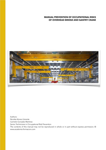
Rehabilitation of theFremont Bridge inSeattle, WashingtonSpan Lock MachineryThe Fremont Bridge utilizes a novel center lock that was developed by the City of SeattleEngineering Department and utilized at all of the City-owned bascule bridges. The designfeatures an overlapping jaw and guide design that virtually eliminates bending stresses from thelock key, allowing for a relatively compact lock key.General Arrangement of the original span lock machinery, Historic American Engineering RecordThe center lock machinery utilizes an electric motor driving open gearing and cross shaftinglocated under the roadway. Cranks drive the lock keys via connecting rods to drive and pull thelock keys upon rotation of the motors.The original lock operating machinery was rehabilitated as follows: The bearing journals were polished The bearings were re-babbitted and re-bored The cross shafts were replaced. The brake-motors and motor pinions were replaced.HEAVY MOVABLE STRUCTURES, INC.th12 Biennial Movable Bridge Symposium
Rehabilitation of theFremont Bridge inSeattle, WashingtonRehabilitated span lock operating machineryThe only failing of the original design was the lack of the ability to adjust the clearances in thejaw and guides to account for wearing of the parts. A prior rehabilitation modified the guides toincorporate wear shoes, however no such retrofit was possible for the jaws. During the currentrehabilitation, the guides and jaws were replaced with a new design that included bronze wearshoes. A similar design was used at the retrofit of the University Bridge and the feedback fromthe City after 20 years of service was that that design was performing well.New span lock connecting rod, lock key and guides with bronze wear shoes,shown disengaged.HEAVY MOVABLE STRUCTURES, INC.th12 Biennial Movable Bridge Symposium
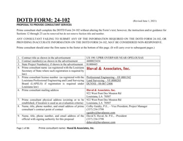
Rehabilitation of theFremont Bridge inSeattle, WashingtonSpan Drive MachineryThe original span drive machinery was still in service at the time of the current rehabilitation.The arrangement of the original machinery placed the 100 HP electric motor, brakes and an openbevel gear type differential in a machinery room enclosure to the rear of the counterweight at thebridge centerline. Line shafting extended from the differential to bevel gear sets. The bevel gearsets are connected to an open gear frame located outboard of the bascule leaf by additional lineshafting. Rack pinions are on the final shafts. The rack pinions drive 5 ½” circular pitch internalcurved racks mounted on the bascule trusses.Arrangement of existing span drive machineryAll of the existing span drive machinery, with the exception of the racks, was replaced as part ofthe rehabilitation. Mechanically independent drives were utilized at each quadrant of the bridge.This configuration offered the following advantages: The space utilized for the existing machinery rooms that contained the original motors anddifferential gears was not large enough for this equipment plus all of the new electricalequipment. The elimination of the differential avoided the need for additional electricalroom space.HEAVY MOVABLE STRUCTURES, INC.th12 Biennial Movable Bridge Symposium
Rehabilitation of theFremont Bridge inSeattle, Washington The independent drives provide an additional degree of mechanical and electricalredundancy in that each leaf can be operated using one drive at normal speed. The onlylimitation is the maximum acceptable wind speed for operation is reduced.Each drive is provided with a 75 HP motor. The number of teeth on the rack pinions wasincreased by one from 16 to 17. The new drive machinery was designed to open the bridge74 in a time of 76 seconds.The design of the new machinery features a new, custom designed secondary reducer with therack pinion shaft mounted on the overhung output shaft extension. The machinery brake ismounted on a support that is integral with the secondary reducer housing. All of the othermachinery, including the motor, motor brake, primary reducer and electrical controlequipment was mounted on a single support. All of the machinery was mounted, aligned andinspected in the shop prior to delivery to the bridge site. The only field alignment requiredwas to mate the rack pinion with the existing racks, anchor the secondary reducer, align thereducer coupling and anchor the machinery support.HEAVY MOVABLE STRUCTURES, INC.th12 Biennial Movable Bridge Symposium
Rehabilitation of theFremont Bridge inSeattle, WashingtonConstructionThe rehabilitation contract was awarded in September, 2005. The Prime Contractor for therehabilitation was the Mowat Contruction Company. The contract value was 36.3 million. Ofthis, 28.8 million is for replacing the approaches and 7.5 million is for upgrading themechanical and electrical system.The project was staged so that the work on the approaches was started immediately. While thework on the approach replacement was underway, the shop drawings were developed andfabrication, testing and shop inspection of the machinery was completed. The replacement of theapproaches was completed in May 2007.North approach replacement underwaySouth approach replacement underwayHEAVY MOVABLE STRUCTURES, INC.th12 Biennial Movable Bridge Symposium
Rehabilitation of theFremont Bridge inSeattle, WashingtonDuring development of the shop drawings, prior to removal of the existing machinery, theContractor was tasked with performing detailed measurements of the existing racks to facilitatespeedy installation of the new machinery. The span drive machinery sub-contractor was TheGear Works, located in Seattle. Field measurements of each existing gear rack were taken toascertain the point of tightest mesh with the new output pinions. This required the use of aunique portable composite tester specially built for the project (nicknamed the “slinky”). Theslinky accounted for the uneven wear of the existing cast steel rack teeth. Based on thesemeasurements, each pinion was custom manufactured with a special modified tooth form tooptimize the strength of the teeth and ensure that the desired backlash could be achieved withoutthe risk of tip interference.The “slinky” portable composite tester built by The Gear WorksA 200% load test was applied to the gearboxes by using an electrical regenerative method. Over2,500,000 lb./in. of torque was applied to the low speed shafts in both directions. The load testswere conducted at The Gear Works manufacturing facility in Seattle. The gearboxes wereassembled back to back on an 18" thick concrete foundation to allow for rigid load testpositioning. All gear contact patterns and bearing settings were checked and recorded before andafter testing.HEAVY MOVABLE STRUCTURES, INC.th12 Biennial Movable Bridge Symposium
Rehabilitation of theFremont Bridge inSeattle, WashingtonReducer 200% Load Test Arrangement at The Gear Works, SeattleFollowing acceptance of the load tests and other shop inspection, the temporary winch drivesystem was installed at the north leaf. The winch system was commissioned during a night timeclosure of the bridge to vehicular traffic. The existing span drive machinery and electricalsystems for the north leaf were then removed and the piers were prepared for installation of thenew machinery.Machinery support assembly ready for installation.In order to install the new secondary reducers and machinery support assembly, the leaf wasopened and the reducers were lowered into the counterweight pit. Rigging was then installed toHEAVY MOVABLE STRUCTURES, INC.th12 Biennial Movable Bridge Symposium
Rehabilitation of theFremont Bridge inSeattle, Washingtonlift the reducers and machinery support assemblies up to the machinery level where they wereplaced over their anchor bolts, which had been previously installed.Secondary reducer installation sequence.Once all of the machinery was in position for the North leaf, the secondary reducers werelowered into position so that the rack pinion engaged the rack during a night time closure tovehicular traffic. The leaf position corresponding to the minimum backlash had been previouslyestablished based on the “slinky” measurements. The leaf was opened to that position, thepinion was aligned and the reducer secured with the desired backlash and the leaf was openedusing the winch to establish the contact pattern on the new pinion and existing rack.HEAVY MOVABLE STRUCTURES, INC.th12 Biennial Movable Bridge Symposium
Rehabilitation of theFremont Bridge inSeattle, WashingtonEvaluating rack pinion tooth contact during installation of the secondary reducers.Each secondary reducer was aligned during a single night time closure and temporarily securedagainst jack screws. The machinery support assembly was then positioned so that the reducercouplings were aligned. The secondary reducers and machinery supports were then grouted andanchored permanently using epoxy anchors. Each of the anchors was pull tested to designcapacity to verify integrity and then hydraulically tensioned.HEAVY MOVABLE STRUCTURES, INC.th12 Biennial Movable Bridge Symposium
Rehabilitation of theFremont Bridge inSeattle, WashingtonOperational TestingFollowing completion of the anchorage of the machinery, the new span drive machinery andcontrols were commissioned. SBE performed dynamic strain gage measurements during thecommissioning tests for the dual purposes of verifying the electronic load sharing functions ofthe drives and also for determination of span balance.Operational testing of new span drive machineryOne interesting piece of information that was gained from the strain gage testing related to thebrake performance under emergency stop conditions. The shoe brakes are spring set, thrustorreleased units and are provided with an adjustable time delay. During the initial testing, themotor brake time delays were set at their minimum setting and the machinery brakes wereadjusted with a 4-5 second delay. After physically verifying the brake torque with a torquewrench (equivalent to 95% FLT of the motor) using the breakaway method, an emergency stopwas performed with the bridge operating at full speed. It was noted that the peak braking torquewas nearly 300% FLT of the motor. Further testing with a time delay of approximately 2seconds resulted in a nearly 50% reduction in peak braking torques. In order to avoid excessiveshock loading of machinery, a 2 second time delay was utilized at all motor brakes and a 6second time delay was used for the machinery brakes.HEAVY MOVABLE STRUCTURES, INC.th12 Biennial Movable Bridge Symposium
Rehabilitation of theFremont Bridge inSeattle, WashingtonEmergency stop testing of new span drive machinery with no time delayOnce the new span drive machinery for the north leaf was successfully tested, the winchoperating system was removed and installed at the south leaf, where the process was repeated.HEAVY MOVABLE STRUCTURES, INC.th12 Biennial Movable Bridge Symposium
Rehabilitation of theFremont Bridge inSeattle, WashingtonThe rack, new pinion and machinery shield viewed from inside the bascule leaf.The new span drive motor, primary reducer, motor and machinery brakes viewedfrom the machinery room.HEAVY MOVABLE STRUCTURES, INC.th12 Biennial Movable Bridge Symposium
Rehabilitation of theFremont Bridge inSeattle, WashingtonConstruction IssuesThere were very few problems encountered during the mechanical rehabilitation that related toexisting field conditions. Two of the notable issues related to the poor condition of existingconcrete.During construction of the temporary winch system it was necessary to anchor sheave brackets tothe counterweight box. It was intended that epoxy anchors would be used. During constructionlarge voids and poor quality concrete were discovered. Despite attempts to fill the voids withgrout, it was not possible to anchor the sheave brackets and an alternative plan involving weldingthe brackets to the counterweight box was used.Machinery anchorage modifications.Unsound concrete was also discovered during modifications to the machinery floor that thesecondary reducers were anchored to. In order to ensure the integrity of the reducer anchorage,the unsound concrete was chipped out, reinforced and re-poured.HEAVY MOVABLE STRUCTURES, INC.th12 Biennial Movable Bridge Symposium
Rehabilitation of theFremont Bridge inSeattle, WashingtonCommissioning of the south leaf span drive machinery was completed in February 2008followed by functional testing of the electrical control system. Rehabilitation of the span lockswas completed in April 2008.The completion of the mechanical and electrical rehabilitation of the 91 year old Fremont Bridgewill ensure continued long term reliable operation of a critical component of the infrastructure ofthe City of Seattle.Fremont Bridge, opening for the tall ships parade. Seattle Municipal Archives Photograph CollectionHEAVY MOVABLE STRUCTURES, INC.th12 Biennial Movable Bridge Symposium
The system designed by SBE was built for use on the University Bridge rehabilitation, loaned to Multnomah County, Oregon for use during a rehabilitation of the Broadway Bridge in the 90's. The system was returned to Seattle and used at the Ballard Bridge rehabilitation before utilizing it for the Fremont rehabilitation project.