Transcription
RS-232 Baud Rate ConverterModel 232BRCDocumentation Number 232BRC-0812pn5104-r006This product designed and manufactured in Ottawa, Illinois USAof domestic and imported parts by707 Dayton Road -- P.O. Box 1040 -- Ottawa, IL 61350 USAPhone (815) 433-5100 -- General Fax (815) 433-5105Phone (815) 433-5100 -- General Fax (815) 433-5105Website: www.bb-elec.comSales e-mail: orders@bb-elec.com -- Fax (815) 433-5109Technical Support e-mail: support@bb.elec.com -- Fax (815) 433-5104European HeadquartersB&B ElectronicsWestlink Commercial Park -- Oranmore, Co. Galway, IrelandPhone 353 91-792444 -- Fax 353 91-792445Website: www.bb-europe.comSales e-mail: sales@bb-europe.comTechnical Support e-mail: support@bb-europe.comB&B Electronics – Revised November 2007Manual Documentation Number 232BRC-0812Cover PageB&B Electronics Mfg Co Inc – 707 Dayton Rd - PO Box 1040 - Ottawa IL 61350 - Ph 815-433-5100 - Fax 815-433-5104 – www.bb-elec.comB&B Electronics – Westlink Commercial Park – Oranmore, Galway, Ireland – Ph 353 91-792444 – Fax 353 91-792445 – www.bb-europe.com
TABLE OF CONTENTSChapter 1: INTRODUCTION . 3Applications . 3Specifications . 4Default Parameters . 4Checklist . 5Chapter 2: OPERATION . 7Port Configurations . 7Port Connections . 9LED Indicators . 11Chapter 3: SETUP SOFTWARE . 13Introduction . 13Connection . 13Software Installation . 14Software Uninstall . 14Setup Tutorial . 14Main Screen . 15Copying Parameters Between Units . 16Final System Installation . 17Default Parameters . 17Appendix A: Cable Charts .A-1Port A Connections .A-1Chart A.1. DTE (PC) DB9 to Port A (DCE) .A-1Chart A.2. DTE (PC) DB25 to Port A (DCE) .A-1Chart A.3. DCE (Modem) DB9 to Port A (DCE) .A-2Chart A.4. DCE (Modem) DB25 to Port A (DCE) .A-2Port B Connections .A-2Chart A.5. DCE (Modem) DB9 to Port B (DTE) .A-2Chart A.6. DCE (Modem) DB25 to Port B (DTE) .A-3Chart A.7. DTE (PC) DB9 to Port B (DTE) .A-3Chart A.8. DTE (PC) DB25 to Port B (DTE) .A-3Appendix B: Block Diagram . B-1Appendix C: Declaration of Conformity . C-1232BRC-0812 ManualTable of ContentsB&B Electronics Mfg Co Inc – 707 Dayton Rd - PO Box 1040 - Ottawa IL 61350 - Ph 815-433-5100 - Fax 815-433-5104B&B Electronics – Westlink Commercial Park – Oranmore, Galway, Ireland – Ph 353 91 792444 – Fax 353 91 792445i
Chapter 1: INTRODUCTIONThe 232BRC acts as a translator between devices withincompatible asynchronous serial communications. Each port uses adedicated UART and includes a 16 kbyte receive buffer. Each portcan be independently configured for data rate, data format, andhandshaking.Each side of the 232BRC can be configured to match theconnected device. It supports any data rate up to 115.2 kbps and allstandard data formats. Each side can either supply or accepthardware or software handshaking. Setup parameters are configuredthrough the PC setup software provided and saved in non-volatilememory.The 232BRC is supplied with two DB9 connectors. The femaleconnector is configured as a DCE for connecting to PCs, Terminals,and other DTE devices. The male connector is configured as a DTEfor connecting to Modems and other DCE devices. Three LEDsindicate power and the presence of data in either port’s buffer.ApplicationsConnect devices with different data rates.Convert from hardware to software handshaking.Convert between data formats.Add handshaking to a streaming device.Use as a port buffer to increase throughput.232BRC-0812 ManualB&B Electronics Mfg Co Inc – 707 Dayton Rd - PO Box 1040 - Ottawa IL 61350 - Ph 815-433-5100 - Fax 815-433-5104B&B Electronics – Westlink Commercial Park – Oranmore, Galway, Ireland – Ph 353 91 792444 – Fax 353 91 7924453
SpecificationsModel:Interface:Data Bits:Parity:Data Rate:Stop Bits:Flow Control:Buffer Memory:LEDs:Power Requirements:Power Connector:Recommended Supply:Data Connectors:Dimensions:Setup Software:Supplied Accessories:232BRCRS-232 Asynchronous5, 6, 7, or 8Even, Odd, or None300 to 115.2 kbps1 or 2Hardware(RTS/CTS),Software(XON/XOFF), or None16 Kbytes SRAM per portBuffer A, Buffer B, Power 12 to 17 VDC @ 60mA max.2.5mm Phono Jack ( Tip)B&B Model 232PSPort A DB9 FemalePort B DB9 Male5.8 x 3.6 x 1.2 in. (14.6 x 9.1 x 3.0 cm)PC compatible,Windows 95/98/NT/2000/VistaSoftwareInstruction ManualDefault ParametersWhen shipped, the 232BRC comes set up for the followingparameters for ports A and B:Data Rate 9600 bpsData Bits 8Stop Bits 1Parity NoneHandshaking NoneRefer to the following sections of the manual for what each ofthese parameters means and how they can be changed.4232BRC-0812 ManualB&B Electronics Mfg Co Inc – 707 Dayton Rd - PO Box 1040 - Ottawa IL 61350 - Ph 815-433-5100 - Fax 815-433-5104B&B Electronics – Westlink Commercial Park – Oranmore, Galway, Ireland – Ph 353 91 792444 – Fax 353 91 792445
ChecklistExamine the shipping carton and contents for physical damage.If damage is found, file a claim with the shipper immediately.The following equipment should be in the shipping carton:1. RS-232 Baud Rate Converter model 232BRC2. Instruction Manual3. SoftwareIf any of the items above are not in the shipping carton contactthe shipper immediately.232BRC-0812 ManualB&B Electronics Mfg Co Inc – 707 Dayton Rd - PO Box 1040 - Ottawa IL 61350 - Ph 815-433-5100 - Fax 815-433-5104B&B Electronics – Westlink Commercial Park – Oranmore, Galway, Ireland – Ph 353 91 792444 – Fax 353 91 7924455
6232BRC-0812 ManualB&B Electronics Mfg Co Inc – 707 Dayton Rd - PO Box 1040 - Ottawa IL 61350 - Ph 815-433-5100 - Fax 815-433-5104B&B Electronics – Westlink Commercial Park – Oranmore, Galway, Ireland – Ph 353 91 792444 – Fax 353 91 792445
Chapter 2: OPERATIONEach port receives data from its connected device, buffers thedata, and sends it out the opposite port when that port’s handshakingindicates it is ready to receive data. Each port is set to match therequirements of its connected device through the setup software.Unused output handshake lines are held high by the 232BRC. Pin6 (DSR) on Port A and Pin 4 (DTR) on Port B are held in a constanttrue state. This provides a constant enabled signal to connecteddevices that need it, or provides a positive voltage to devices thatderive their power from these lines.Port ConfigurationsThe 232BRC provides a dedicated UART to ports A and B. Thisallows each port to be individually configured for baud rate, numberof data bits, parity, and hardware (RTS/CTS) or software(XON/XOFF) handshaking. Configuration parameters are setthrough the setup software.Baud rate:Each port supports the following standard baud rates:300600120024004800960019.2k38.4k57.6kor 115.2 kbpsIn addition, non-standard baud rates between 300 and 115.2kbps can also be set. The 232BRC uses a 1.152 MHz clock for itsbase data rate, so any rate that can be evenly divided into 1.152 MHzcan be set exactly.For example:28.8 kbps 1.152 MHz / 40232BRC-0812 ManualB&B Electronics Mfg Co Inc – 707 Dayton Rd - PO Box 1040 - Ottawa IL 61350 - Ph 815-433-5100 - Fax 815-433-5104B&B Electronics – Westlink Commercial Park – Oranmore, Galway, Ireland – Ph 353 91 792444 – Fax 353 91 7924457
Baud rates that are not evenly divisible into 1.152 MHz can alsobe used, but the actual baud rate will vary slightly from the requestedrate. This may or may not cause data errors, depending on theattached equipment. Most standard UARTs can accept a 5% to 10%difference in baud rate before errors occur.For example:Desired Baud Rate 20 kbps1.152 MHz / 20 kbps 57.6Actual Rate 1.152 MHz / 58 19.862 kbps%error (20 kbps – 19.862 kbps) / 20 kbps * 100%error 0.7%Data bits:Each port can be configured for Five, Six, Seven or Eight databits. NOTE: If the ports are set up differently, the port set for fewerdata bits cannot transmit the upper most significant bits.Parity:Each port can be configured for Even, Odd, or No parity. Theparity should be selected to match the connected device.Stop Bits:Each port can be configured for one or two stop bits. The stopbits should be selected to match the connected device.Flow Control:Hardware(RTS/CTS) Handshaking:Each port can be independently configured to hold data untilits input handshake line goes high. On Port A, pin seven (RTS)would have to be held high by the connected device in order for the232BRC to send data. On Port B, pin eight (CTS) needs to be heldhigh by the connected device for the 232BRC to send data.Connected devices can prevent data from being sent from the232BRC by holding their corresponding handshake lines low. Thiscorresponds to pin seven on Port A and pin eight on Port B. SeeAppendix A for a complete table of signal directions.8232BRC-0812 ManualB&B Electronics Mfg Co Inc – 707 Dayton Rd - PO Box 1040 - Ottawa IL 61350 - Ph 815-433-5100 - Fax 815-433-5104B&B Electronics – Westlink Commercial Park – Oranmore, Galway, Ireland – Ph 353 91 792444 – Fax 353 91 792445
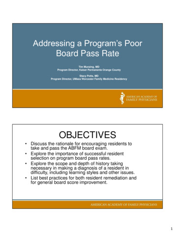
Software(XON/XOFF) Handshaking:Each port can be independently configured for softwarehandshaking. Software handshaking is normally used incommunications links where the main data stream is one way, suchas to a printer. The main sending device is expected to hold off itsdata when it receives the XOFF(13 Hex) character, and resumesending when it receives an XON(11 Hex). The main receivingdevice is expected to send the XOFF character if the buffer is full orit otherwise needs to hold off the data.The 232BRC can be set to emulate either the main sendingdevice or the receiving device. It can either supply the XON/XOFFhandshake or stop sending data with the XON/XOFF. The port wouldnormally be set to supply the XON/XOFF characters if it is connectedto a fast sending device. It would be set to receive the XON/XOFFhandshaking if the port is connected to the slower receiving device.Port ConnectionsIn order to determine the proper port connections to the232BRC, it is necessary to have a basic understanding of the termsDCE and DTE. RS-232 was designed, using DB-25 connectors, forconnecting a DTE (Data Terminal Equipment) device to a DCE (DataCommunication Equipment) device. Each device will have inputs onpins that correspond to outputs on the same pins of the other device.For example, a DTE device will transmit data out on pin 2 (on a DB25) and a DCE device will receive data in on pin 2 (on a DB-25). IBMPCs and serial printers are DTE devices, modems are DCE devices.Originally the RS-232 Standard specified only a 25 pin, D-subconnector. Since then, the use of a 9 pin, D-sub supporting only aportion of the original RS-232 signals has been used extensively,starting with the IBM PC and migrating into other peripherals. The pinouts for this 9 pin connector have since become the EIA/TIA 574Standard. This standard specifies a DTE device that transmits on pin3 and receives on pin 2, with the DCE having the oppositeconfiguration. Figure 2.1 shows the signal direction for 25 pin and 9pin devices configured as a DTE and DCE.232BRC-0812 ManualB&B Electronics Mfg Co Inc – 707 Dayton Rd - PO Box 1040 - Ottawa IL 61350 - Ph 815-433-5100 - Fax 815-433-5104B&B Electronics – Westlink Commercial Park – Oranmore, Galway, Ireland – Ph 353 91 792444 – Fax 353 91 7924459
25 Pin DTE2 (TD)TRR20 (DTR)TRRR6 (DSR)8 (DCD)7 (GND)2 (RD)RR8 (CTS)R4 (DTR)TRR6 (DSR)1 (DCD)5 (GND)T RS-232 TransmitterRTTRR6 (DSR)8 (DCD)7 (GND)RTT7 (RTS)8 (CTS)T20 (DTR)3 (TD)2 (RD)T4 (RTS)5 (CTS)T9 Pin DCE2 (TD)3 (RD)T7 (RTS)T5 (CTS)25 Pin DCE3 (TD)T3 (RD)4 (RTS)T9 Pin DTE4 (DTR)6 (DSR)1 (DCD)5 (GND)R RS-232 ReceiverFigure 2.1. DTE/DCE Port DiagramsPort A ConnectionsPort A of the 232BRC is a 9 pin, female D-sub connectorconfigured as a DCE. This provides direct connection to an IBM PCcompatible or other DTE device. If it is necessary to connect Port Ato a modem or other device configured as a DCE, a null modemadapter or cable is needed.See Appendix A for a complete set of connection tables to the232BRC ports.Port B ConnectionsPort B of the 232BRC is a 9 pin male D-sub connector configuredas a DTE. This provides direct connection to a modem or other DCEdevice. If it is necessary to connect Port B to a PC or other deviceconfigured as a DTE, a null modem adapter or cable is needed.See Appendix A for a complete set of connection tables to the232BRC ports.Power ConnectionsPower to the 232BRC is supplied through the 2.5mm Phono jackon the side of the unit (Tip Positive). The 232BRC has an integratedregulator, allowing it to operate on any supply voltage between 12 to 17 VDC. The
Manual Documentation Number 232BRC-0812 Cover Page B&B Electronics Mfg Co Inc – 707 Dayton Rd - PO Box 1040 - Ottawa IL 61350 - Ph 815-433-5100 - Fax 815-433-5104 – www.bb-elec.com B&B Electronics – Westlink Commercial Park – Oranmore, Galway, Ireland – Ph 353 91-792444 – Fax 353 91-792445 – www.bb-europe.com RS-232 Baud Rate Converter