Transcription
MANUAL OFSTANDARD PRACTICEWIRE REINFORCEMENT INSTITUTE 942 Main Street Suite 300 Hartford, CT 06103 (800) 552-4WRI [4974]STRUCTURAL WELDEDWIRE REINFORCEMENT21WIRE REINFORCEMENT INSTITUTE, INC.Excellence Set in Concretewww.wirereinforcementinstitute.org
Manual ofStandard PracticeStructural WeldedWire ReinforcementIncludes latest developments on use of WWRunder American Concrete Institute Building Code 318Prepared under direction of the technical committees of theWire Reinforcement Institute, IncorporatedWRI942 Main Street, Suite 300Hartford, CT 06103Phone: (800) 522-4WRI [4974]Fax: (860) 808-3009www.wirereinforcementinstitute.orgPhoto Captions for Front Cover Photos1 – Jacking bars are used to properly position WWRafter ready mix trucks leave and before screedingtakes place.2 – Properly positioning two layers of WWR onsteel supports.
Table of Contents1.Welded Wire Reinforcement .32.Nomenclature .42.12.22.32.43.Manufacturing and Availability .63.13.23.33.44.Item Description .4Wire Size Designation .4Style .4Dimensions .5Manufacturing Process .6Minimum Quantity Requirements .7Common Sizes .7Individual Project Needs.7Specifications and Properties .84.14.24.34.4ASTM Specifications.8WWR Coating .8Yield Strength (elongation test criteria) .8-9Weld Shear Strength .8-95.Building Code Requirementsfor Reinforced Concrete (ACI 318) .11-186.Design Aids .19-26Sectional Area Table .19-20Development & Splice Lengths Deformed WWR .21-22Development & Splice Lengths Plain WWR .23-24Wire Size Comparison Tables .25-267.Handling, Shipping and Unloading .278.Placing .289.Weight (Mass) Calculation .29Weight (Mass) Estimating Tables.30-33 Copyright July 2001 Wire Reinforcement Institute, Inc.WWR-500 6th Edition Last Printing, 1999Printed in U.S.A.This manual is furnished as a guide for the selection of welded wire reinforcement with theunderstanding that while every effort has been made to insure accuracy, neither the Wire ReinforcementInstitute, Inc., nor its member companies make any warranty of any kind respecting the use of the manualfor other than informational purposes.
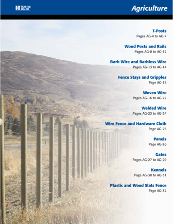
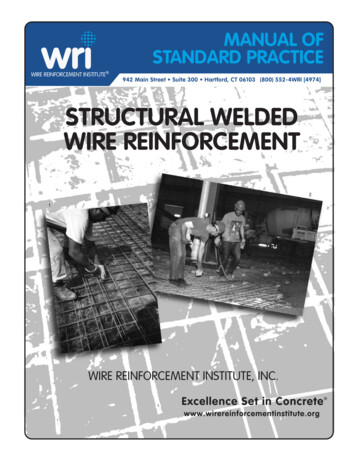
Welded Wire Reinforcement1Welded wire reinforcement (WWR) is a prefabricatedreinforcement consisting of parallel series of highstrength, cold-drawn or cold-rolled wire welded togetherin square or rectangular grids. Each wire intersection iselectrically resistance-welded by a continuous automaticwelder. Pressure and heat fuse the intersecting wires intoa homogeneous section and fix all wires in their properposition. Plain wires, deformed wires or a combination ofboth may be used in WWR.Welded plain wire reinforcment bonds to concrete by thepositive mechanical anchorage at each welded wire intersection. Welded deformed wire utilizes deformations pluswelded intersections for bond and anchorage.Concrete structures are being successfully and economically reinforced with high-strength, uniformly distributedwires in WWR. The smaller diameter, closely-spacedwires of WWR provide more uniform stress distributionand more effective crack control in slabs and walls. Thewide range of wire sizes and spacings available makes itpossible to furnish the exact cross-sectional steel arearequired. The welded crosswires hold the reinforcementin the proper position, uniformly spaced. The ease andspeed with which WWR can be handled and installedconsiderably reduces placing time, resulting in reducedcost. Reduced construction time is of particular benefit toSection at typical weld showing complete fusion of intersectingwires.the owner by affording earlier occupancy and reducingtotal (project) cost. Material savings can be realized byspecifying WWR with higher yield strengths as recognized by ACI 318 and ASTM. Consult various manufacturers for their high-strength capabilities.This manual provides WWR product information, material specifications, design and detailing requirements, andvarious tables and design aids for those interested in thedesign and construction of reinforced concrete structures.Placing a shear cage of welded wire reinforcement in a concrete girder for a sports stadium.3
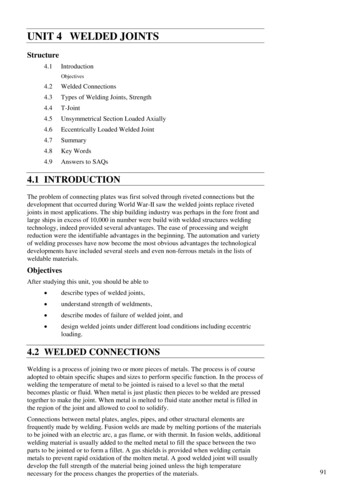
Nomenclature22.1 Item Description2.3 StyleIn the welded wire industry, an “item” is the term used todesignate a complete unit of WWR as it appears on anorder form.Spacings and sizes of wires in WWR are identified by“style.” A typical style designation is:2.2 Wire Size DesignationThis denotes a unit of WWR in which:Individual wire (plain and deformed) size designations arebased on the cross-sectional area of a given wire. Gagenumbers were used exclusively for many years. The industrychanged over to a letter-number combination in the 1970’s.The prefixes “W” and “D” are used in combination with anumber. The letter “W” designates a plain wire and the letter“D” denotes a deformed wire. The number following theletter gives the cross-sectional area in hundredths of asquare inch. For instance, wire designation W4 would indicate a plain wire with a cross-sectional area of 0.04 sq. in.;a D10 wire would indicate a deformed wire with a crosssectional area of 0.10 sq. in. The size of wires in weldedwire mesh is designated in the same manner. This systemhas many advantages. Since the engineer knows the crosssectional area of a wire and the spacing, the total crosssectional area per foot of width can easily be determined.For instance, a W6 wire on 4 inch centers would provide 3wires per foot with a total cross-sectional area of 0.18 sq. in.per foot of width.When describing metric wire, the prefix “M” is added. MWdescribes metric plain wire and MD metric deformedwire. The wire spacings in metric WWR are given in millimeters (mm) and the cross-sectional areas of the wiresin square millimeters (mm2).Nominal cross-sectional area of a deformed wire isdetermined from the weight (mass) per foot of wire ratherthan the diameter.6 x 12–W12 x W5 Spacing of longitudinal wire Spacing of transverse wires Size of longitudinal wires Size of transverse wires 6” (152mm)12” (305mm)W12 (0.12 sq. in.)(77mm2)W5 (.05 sq. in.)(32mm2)Thus, the style for the sample above would be expressedmetrically as 152 x 305–MW77 x MW32. A weldeddeformed wire style would be noted in the same mannerby substituting the prefix D for the W. Note that “style”gives spacings and sizes of wires only and does not provide any other information such as width and length ofsheet.WWR with non-uniform wire spacings is available. In thiscase, special information is added to the style designation to describe the reinforcement.It is very important to note that the terms longitudinal andtransverse are related to the manufacturing process anddo not refer to the relative position of the wires in a concrete structure. The WWR manufacturing process is discussed in detail in section 3.1. Transverse wires areindividually welded at right angles as the reinforcementadvances through the welder. In some WWR machines,the transverse wire is fed from a continuous coil; inothers they are precut to length and hopper fed to thewelding position.LengthIndustry Method of Designating Style:Example–6 x 12–W12 x W5idthrall WOvethWidEnd Overhangs–Thesum of the end overhangsshould equal onetransverse wire space.Unless otherwisespecified, each endoverhang equals one-halfof a transverse space.Longitudinal wireTransverse wireLongitudinalwire spacingLongitudinalwire sizeTransverseTransversewire sizewire spacingSide Overhangs may bevaried as required and donot need to be equal.Overhang lengths limitedonly by overall sheet widthFigure 1 Nomenclature4
2.4 DimensionsDescription of width, length and overhang dimensions of sheets follow:Width Center to center distance betweenoutside longitudinal wires. This dimension does not include overhangs.Side Overhang Extension of transverse wires beyondcenterline of outside longitudinalwires. If no side overhang is specified,WWR will be furnished with overhangs on each side, of no greaterthan 1 inch (25 mm). Wires can be cutflush (no overhangs) specified thus:( 0”, 0”). When specific overhangsare required, they are noted thus:( 1”, 3”) or ( 6”, 6”).Overall Width Width including side overhangs, in. (ormm). In other words the tip-to-tipdimension of transverse wires.Length Tip-to-tip dimension of longitudinalwires. Whenever possible this dimension should be an even multiple of thetransverse wire spacing. [The lengthdimension always includes endoverhangs.]End Overhangs Extension of longitudinal wires beyondcenterline of outside transverse wires.Unless otherwise noted, standard endoverhangs are assumed to be requiredand end overhangs need not bespecified. Non-standard end overhangs may be specified for specialsituations; preferably the sum of thetwo end overhangs should equal thetransverse wire spacing.(Above) Inner and outer vertical face of wall reinforcement.The following example of welded wire reinforcement items illustrates how a typical order using the nomenclaturedescribed might appear:Item123Quantity1000 Sheets150 Sheets500 SheetsStyle12 x 12–W11 x W116 x 6–W4 x W46 x 12–D10 x D6Width90”60”96”Side Overhangs( 6”, 6”)( 0”, 0”)( 3”, 6mm1524mm2438mmSide Overhangs( 152, 152)( 0, 0)( 76, 76)Lengths4.6m6.1m5.2mA sample metric order would appear as follows:Item123Quantity1000 Sheets150 Sheets500 SheetsStyle305 x 305–MW71 x MW71152 x 152–MW26 x MW26152 x 305–MD65 x MD395
Manufacturing & Availability3.1 Manufacturing ProcessThe wire used in welded wire reinforcement is producedfrom controlled-quality, hot-rolled rods. These rods arecold-worked through a series of dies or cassettes toreduce the rod diameter to the specified diameter; thiscold-working process, increases the yield strength of thewire. Chemical composition of the steel is carefullyselected to give proper welding characteristics in additionto desired mechanical properties.3welding heads, wire straighteners and feed tubes while achange in length requires only an adjustment in thetiming sequence of the shear which cuts the sheet toproper length.For economy the more difficult machine changes requireminimum quantities per item in order to offset theadditional production time required. Consult manufacturers forstocked quantities or minimum quantities of specialstyles.WWR is produced on automatic welding machines whichare designed for long, continuous operation. Longitudinalwires are straightened and fed continuously through themachine. Transverse wires, entering from the side or fromabove the welder, are individually welded at right anglesto the longitudinal wires each time the longitudinal wiresadvance through the machine a distance equal to onetransverse wire spacing.WWR is manufactured with the following variables:1. Longitudinal wire spacing2. Longitudinal wire size3. Width4. Side and end overhangs5. Transverse wire size6. Transverse wire spacing7. LengthThese variables may be changed during manufacturingwith different amounts of time required depending on thetype and extent of the change (or combination ofchanges). The above listing is in the general order of timeinvolved, with the most time-consuming operation listedfirst. For example, a change in longitudinal wire spacingsfrom one item to another requires the repositioning of allLatest WWR machinery canweld to 3/4” diameter wires.WWR used in highwaymedian barriers.6
3.2 Minimum Quantity Requirements3.4 Individual Project NeedsThe use of welded wire reinforcement becomesmore efficient and economical as the amount of repetition in reinforcement increases. Economy is governed by the manufacturing process as described inSection 3.1 and by the industry practice of carryingcertain common welded wire reinforcement items instock or inventory.Individual projects will require non-standard WWRsizes and styles in order to meet specific reinforcingneeds. Minimum quantity requirements for non-standard orders vary by producer but the following guidelines for maximizing economy of orders can be used.The following two sections outline the minimumquantity requirements for stock (inventoried) itemsand non-standard items.3.3 Common SizesCertain items of welded plain or deformed WWR arecarried in stock by many WRI members either at theproducing mills or warehousing points. While practice varies somewhat between manufacturers andlocalities, many of the items listed in Table 1 areusually available.1. The most important factor affecting economy is tominimize the number of longitudinal wirespacings. An example is using wide spacedwires, but placing 1/2 size, closely spaced wiresat edges, in the splice zones to obtain therequired steel area per foot or meter.2. The second most important factor is controllingthe number of different wire sizes. Many weldingmachines have variable step spacing capabilities. This feature becomes necessary to manufacture sheets, which require variable spacingsused to fabricate column tie and beam stirrupcages. One transverse size, therefore is used toobtain the required steel areas.Common sheet sizes are:CustomaryMetricin. ft.U.S. (except west coast) .96 x 12.5mm M2438 x 3.8U.S. (west coast) .96 x 1696 x 2084 x 2084 x da 382438Mx 2.4x 3.7x 4.3x 4.9x 6.1A1&4B1C1D1E11234Group A – Compares areas of WWR at a minimum fy 65,000 psiGroup D – Compares areas of WWR at a minimum fy 75,000 psiGroup B – Compares areas of WWR at a minimum fy 70,000 psiGroup E – Compares areas of WWR at a minimum fy 80,000 psiGroup C – Compares areas of WWR at a minimum fy 72,500 psiWires may also be deformed, use prefix MD or D, except where only MW or W is required by building codes (usually less than a .MW26 or W4).Also wire sizes can be specified in 1 mm2 (metric) or .001 in (US Customary) increments.For other available styles or wire sizes, consult other WRI publications or discuss with WWR manufacturers.Styles may be obtained in roll form. Note: It is recommended that rolls be flattened and cut to size before placement.7
4Specifications and Properties4.1 SpecificationsThe American Society for Testing and Materials (ASTM)has established specifications for plain and deformedwires as well as welded plain and deformed wirereinforcement. The Canadian Standards Associationpublishes similar standards for use in Canada. Thecorresponding titles and numbers are given in Table 2.Some governmental agencies have special specificationswhich will control.4.2 WWR CoatingsThere are two types of coatings used on welded wirereinforcement. One is galvanized, usually applied to thecold-drawn wire before it is welded into reinforcement.Thehot-dipped galvanizing process is similar to thatspecified in ASTM A641. The other types of coating areepoxy. The application of the epoxy coating occurs afterthe sheets have been welded. The requirements forepoxy-coated welded wire reinforcement are provided inASTM A884.TABLE 2Specifications CoveringWelded Wire ReinforcementU.S.CANADIANSPECIFICATION STANDARD TITLE*ASTM A 82CSA G 30.3ASTM A 185CSA G 30.5ASTM A 496CSA G 30.14ASTM A 497CSA G 30.15Cold-Drawn Plain Steel Wire forConcrete ReinforcementWelded Plain Steel WireReinforcement forConcrete ReinforcementDeformed Steel Wire forConcrete ReinforcementWelded Deformed Steel WireReinforcement for ConcreteReinforcement*The titles of the ASTM Specifications and CSA Standards are identical.4.3 Yield StrengthThe yield strength values shown in Table 3 are ASTMrequirements for minimum yield strength measured at astrain of .005 in/in. The ACI 318 Building Code, Sections3.5.3.4, 3.5.3.5 and 3.5.3.6, state that yield strengthvalues greater than 60,000 psi (414 MPa) may be used,provided they are measured at a strain of .0035 in/in(mm/mm). Higher yield strength welded wire WWR isavailable and can be specified in accordance with ACIcode requirements.Elongation test criteria on maximum strength (or maximum stretch) is shown in tables 3(b) and 3(c).Maximum stretch can be defined as total elongationwhich is a test in A370, A4.4.2, measuring both theelastic & plastic extension.The testing done here and recorded in the Tables 3(b) &3(c) correlate with other testing/research done by somemajor universities. They have found that high strengthWWR is capable of developing significant strains andexhibits sufficient ductility to redistribute the strains toavoid brittle shear failure.4.4 Weld Shear StrengthThe values shown in Table 3 are the ASTM requirementsfor weld shear strength which contribute to the bond andanchorage of the wire reinforcement in concrete.A maximum size differential of wires being welded together is maintained to assure adequate weld shear strength.For both plain and deformed wires, the smaller wire musthave an area of 40 percent or more of the steel area ofthe larger wire.Larger Wire SizeW20 (MW 129)W15 (MW 97)D20 (MD 129)Smaller Wire SizeW8 (MW 52)W6 (MW 39)D8 (MD 52)TABLE 3(a) Minimum Requirements of SteelWires in Welded Wire ReinforcementWELDED PLAIN WIRE REINFORCEMENTASTM A185, CSA G30.5WireSizeW1.2 &overTensileStrengthpsi75,000(520 MPa)YieldStrengthpsi65,000(450 MPa)WeldShearStrength35,000(240 MPa)underW1.270,000(480 MPa)56,000(390 MPa)–WELDED DEFORMED WIRE REINFORCEMENTASTM A497, CSA G30.15TensileWireStrengthSizepsiD 4580,000thru D 4 (550 MPa)under80,000D4(550 MPa)YieldStrengthpsi70,000(480 MPa)70,000(480 MPa)WeldShearStrength35,000(240 MPa)–8
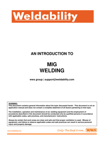
TABLE 3(b) Test of Elongation (total - ElasticTABLE 3(c) Summary of test Criteria in table 3(b)& Plastic) for various Wire SizesGaugeLengthWireSizeElongationMean .40.670.670.050.4978837388969887987”fy @ 0.35%Strain(ksi)ftUltimateTensile@ Fracture(ksi)878010091(27 Samples Tested)fy Rangef Range (ult)@ 0.35% of Strain t73-88ksi91-102 ksi%Elongationtotal*PermanentA370, A4.4.2A370, A4.4.16-14%Mean - 8.9%4-6%5%* Maximum strength or maximum stretch is the full measure of extension beforefracture. It is the true measure of elongation (total). Research background forthis testing can be found in the ACI discussion paper, Disc.88-S60 in ACIStructural Journal, July - August 1992.Note3 samples of each size were tested from the same heat of steel rod7” was the max. gauge length for the testing machine used.Rod (ft) is 55 - 60 ksiRod type is 1006 - 1008 carbon steel.Rate of speed for loading samples averaged 40,000 psi / minute inaccordance with A370 11.4.3Weld Shear TestingExternal Measuring of ElongationWrap Testing9
PARTIAL NOTATIONTERMS USED IN BUILDING CODE REQUIREMENTSFOR REINFORCED CONCRETE (ACI 318)A effective tension area of concrete surrounding the main tension reinforcingbars and having the same centroid as that reinforcement, divided by thenumber of bars, sq. in. (mm2)As area of nonprestressed tension reinforcement, sq. in. / 1ft. (mm2 / m)Aw area of individual wire to be developed or spliced, sq. in. (mm2)c spacing or cover dimension, in. (mm)d distance from extreme compression fiber to centroid oftension reinforcement, in (mm)db nominal diameter of bar, wire, or prestressing strand, in. (mm)dc thickness of concrete cover measured from the extreme tensionfiber to the center of the bar located closest thereto, in. (mm)f 'c specified compressive strength of concrete, psi. (MPa)f 'c square root of specified compressive strength of concrete, psi. (MPa)fs calculated stress in reinforcement at service loads, psi. (MPa)fy specified yield strength of nonprestressed reinforcement, psi. (MPa)h overall thickness of member, in. (mm)d development length, in. (mm)db basic development length, in. (mm)sw spacing of wires to be developed or spliced, in. (mm)z a quantity limiting distribution of flexural reinforcementα reinforcement location factor, horizontal reinforcement 12” of freshconcrete below dbβ coating factorλ lightweight factorγ reinforcement size factor10
Building Code Requirements5Appropriate code provisions concerning features and use ofwelded wire reinforcement are paraphrased and summarizedin the following outline form to identify areas of the code whichspecifically apply to welded wire reinforcement.ACI 318 Code ProvisionsA. Definitions and SpecificationsB. Bond and DevelopmentC. SplicesD. Spacing of WiresE. Minimum Reinforcing RequirementsF. Bends and HooksG. Lateral Reinforcement (Stirrups and Ties)H. Design Methods and DetailsPROVISIONACI 318-99SECTION NUMBERA. Definitions and Specifications1. Welded wire reinforcement (plain and deformed) is defined as deformed reinforcementwhen conforming to subsequent sections .2. Deformed wire conforms to ASTM A496. Minimum yield strength (fy) is consideredto be 60,000 psi (420 MPa) unless measured at 0.35 percent strain .3. Deformed wire reinforcement conforms to ASTM A497. Maximum spacing of weldedintersections in direction of principal reinforcement 16 inches (400mm),except where wire fabric is used as stirrups (12.13.2) .4. Spiral reinforcement plain wire conforms to ASTM A82. Minimum yield strength(fy) is considered to be 60,000 psi (420 MPa) unless measured at 0.35 percent strain .5. Epoxy coated wires and welded wire reinforcement shall comply withASTM A 884.2.13.5.3.43.5.3.63.5.4.23.5.3.8Figure 3 Direction of Principal Reinforcement11
PROVISIONACI 318-99SECTION NUMBERB. Bond and DevelopmentWelded intersections of welded wire reinforcement bond to concrete bymechanical anchorage. See Section 12.7 & 12.8 for bond and developmentof welded wire reinforcement.2’ min.(50mm)12.712.8R12.7Criticalsectionld or 8” (200mm) min.Deformed wire reinforcement:The development length ( d) in inches of diameter db for deformed wire intension shall be determined from equation 12.2.3, d / db shall be:12.2.112.2.212.2.312.2.3in which the term (c Ktr)/db shall not be greater than 2.5.d of welded deformed wire shall not be less than 12”.12.2.1For design simplication, Ktr 0The development length d of welded deformed wire measured from the point of criticalsection to the end of wire shall be computed as the product of the development length dfrom 12.2.2 or 12.2.3 times a welded wire factor from 12.7.2 or 12.7.3. It shall be permittedto reduce the development length in accordance with 12.2.5 (excess reinforcement) whenapplicable, but d shall not be less than 8 in. when using the welded wire factor in 12.7.2.It shall be permitted to use an epoxy-coating factor β of 1.0 in. 12.2.2 and 12.2.3.12.2.4The welded wire factor is:5dbfy-35,000orbut not greater than 1. **fySwFigure 4 Deformed Wire and Welded Deformed WireReinforcement Development Lengths2" calsectionor 6" (150mm) min.The development length ld of welded plain wire measured from the point of criticalsection to the outermost cross wire shall not be less than:***12.812.8except that when reinforcement provided is in excess of that required, this length maybe reduced in accordance with 12.2.5. ld shall not be less than 6 in. (150 mm).Figure 5 Welded Plain Wire Reinforcement Development Length* metric formula**metric formula(***metric formula) ( )fy-240fyor5dbSw12
PROVISIONACI 318-99SECTION NUMBERC. SplicesThe splice length in inches shall be the largest of the values shown infigure below.Splice length - deformed WWR2" min.(50mm)12.18.11.3 calculatedd8" (200mm) min.Table 5 gives typical splice and development lengths for welded deformedwire reinforcement. Note: Overhangs are part of the splice length.Figure 6 Deformed Wire Reinforcement Splice LengthsThe splice length in inches shall be the largest of the values shown inthe figures below.(a) Splice whenAs Provided 2As Required12.19.1but not less than 1 space 2” (50mm) nor 6” (150mm) minimumNote: overhangs must be added to the splice length for welded plainwire reinforcement.(b) Splice whenAs Provided 212.19.2As Required1.5 d2" (50mm) min.Table 6 gives typical splice and development lengths for welded plainwire reinforcement.Figure 7 Plain Wire Reinforcement Splice Lengths13
PROVISIONACI 318-99SECTION NUMBERD. Spacing of Wires1. Maximum spacings in direction of calculated stress from Part 2, Chapter 3,“Materials”:Plain Fabric12” (305mm) .3.5.3.5Deformed Fabric16” (400mm) .3.5.3.6Note: Use above spacings except for welded wire used as stirrupsFor single leg stirrups see 12.13.2.42. In walls and slabs other than concrete joist construction, the principalreinforcement shall not be spaced farther apart than 3 times the wallor slab thickness, nor more than 18 inches (500mm) .12.13.212.13.2.47.6.53. When the design yield strength for tension exceeds 40,000 psi (300 MPa),cross-sections of maximum positive and negative movement shall be soproportioned that the quantity z, given bydoes not exceed 175 kips per in. (30 MN/m) for interior exposureand 145 kips per in. (25 MN/m) for exterior exposure .4. In slabs where principal reinforcement extends in one direction only,shrinkage and temperature reinforcement at right angles to the principalreinforcement shall be spaced not farther apart than 5 timesthe slab thickness, nor more than 18 inches (500mm) .10.6.47.12.2.25. Special provisions for walls require the following maximum spacinglimitations:Vertical 3 times wall thickness or 18 inches (500mm) .14.3.5Horizontal 3 times wall thickness or 18 inches (500mm) .14.3.56. Spacing reinforcement at critical sections shall not exceed two timesthe slab thickness, except in areas of cellular or ribbed construction. ACISection 7.12 governs areas of cellular or ribbed construction in theseslabs . 13.3.27. See page 15 for wire spacing requirements where weldedwire reinforcement is used as shear reinforcement.14
PROVISIONACI 318-99SECTION NUMBERE. Minimum Reinforcing RequirementsFor shrinkage and temperature reinforcement in structurally reinforced slabs*:1. Slabs where welded wire reinforcement with fy 65,000 psi (450 MPa);(ACI 318 assigns fy 60,000 psi (420 MPa) but makes provisionfor the use of higher fy provided the stress corresponds to a strain of0.35%). Use ratio of reinforcement-to-gross concrete area of 0.0018.R3.5.3.57.12.2.1 (b)2. Slabs where welded wire reinforcement exceeds 65,000 psi (450 MPa),60,000 , when f exceeds 60,000 psi (420 MPa), materialyuse 0.0018fyshall be measured at a yield strain of .35%, but not less than 0.0014. .7.12.2.1 (c)3. For two-way slab systems, the area of reinforcement in each direction shallbe determined from moments at critical sections but shall not be less thanthat required by section 7.12. .13.3.1For minimum wall reinforcement:1. Wall designs require the following minimum reinforcement ratios whenreinforced with welded wire reinforcement (wire sizes not larger than W31 or D31)(MW200 or MD200). .Vertical- 0.0012 .Horizontal- 0.0020 .WRI Note – WWR Industry Capability is to W45 or D45 wire sizes.2. Special Provisions for Seismic DesignThe minimum reinforcement radio,ρv, for structural walls:Longitudinal and Transverse - 0.0025.At least two curtains of reinforcement shall be used in a wall if the in-planefactored shear force assigned to the wall
Width Center to center distance between outside longitudinal wires. This dimen-sion does not include overhangs. Side Overhang Extension of transverse wires beyond centerline of outside longitudinal wires. If no side overhang is specified, WWR will be furnished with over-hangs on each side, of no greater than 1 inch (25 mm). Wires can be cut