Transcription
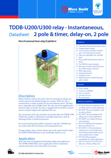
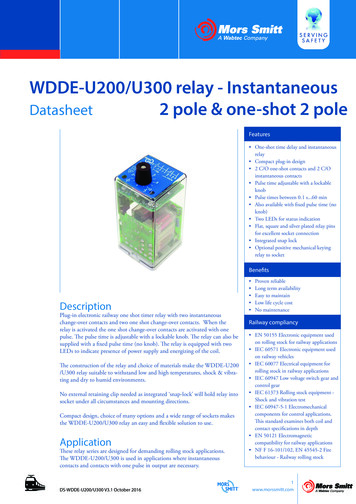
WDDE-U200/U300 relay - InstantaneousDatasheet2 pole & one-shot 2 poleFeatures One-shot time delay and instantaneousrelay Compact plug-in design 2 C/O one-shot contacts and 2 C/Oinstantaneous contacts Pulse time adjustable with a lockableknob Pulse times between 0.1 s.60 min Also available with fixed pulse time (noknob) Two LEDs for status indication Flat, square and silver plated relay pinsfor excellent socket connection Integrated snap lock Optional positive mechanical keyingrelay to socketBenefitsDescriptionPlug-in electronic railway one shot timer relay with two instantaneouschange-over contacts and two one shot change-over contacts. When therelay is activated the one shot change-over contacts are activated with onepulse. The pulse time is adjustable with a lockable knob. The relay can also besupplied with a fixed pulse time (no knob). The relay is equipped with twoLEDs to indicate presence of power supply and energizing of the coil.The construction of the relay and choice of materials make the WDDE-U200/U300 relay suitable to withstand low and high temperatures, shock & vibrating and dry to humid environments.No external retaining clip needed as integrated ‘snap-lock’ will hold relay intosocket under all circumstances and mounting directions.Compact design, choice of many options and a wide range of sockets makesthe WDDE-U200/U300 relay an easy and flexible solution to use.ApplicationThese relay series are designed for demanding rolling stock applications.The WDDE-U200/U300 is used in applications where instantaneouscontacts and contacts with one pulse in output are necessary.DS-WDDE-U200/U300 V3.1 October 2016 Proven reliable Long term availability Easy to maintainLow life cycle costNo maintenanceRailway compliancy EN 50155 Electronic equipment usedon rolling stock for railway applications IEC 60571 Electronic equipment usedon railway vehicles IEC 60077 Electrical equipment forrolling stock in railway applications IEC 60947 Low voltage switch gear andcontrol gear IEC 61373 Rolling stock equipment Shock and vibration test IEC 60947-5-1 Electromechanicalcomponents for control applications.This standard examines both coil andcontact specifications in depth EN 50121 Electromagneticcompatibility for railway applications NF F 16-101/102, EN 45545-2 Firebehaviour - Railway rolling stock1www.morssmitt.com
WDDE-U200/U300 relayTechnical specificationsFunctional and connection diagramsTiming diagramRelay pin correspondenceininstantaneous contacts1214810119137463251one-shot contactspulseConnection diagram2www.morssmitt.comDS-WDDE-U200/U300 V3.1 October 2016
WDDE-U200/U300 relayTechnical specificationsTime delay specificationsTime delay functionAvailable pulse times, adjustableAccuracy - adjustmentOne-shot and instantaneous0.1 s.60 min 10 % of full scale valueAfter adjusting / fixed time setting: no variation insetpointAccuracy - repeatability 0.5 %Time variation - vs voltage variation 0.05 % / % UnomTime variation - vs temperature variation 0.02 % / KPull-in time 15 msRelease time 15 msRecovery time 0.1 sExample pulse time:Pulse time set on 2 s : it will be between 1.8 s.2.2 s.For example: 2.0 s. The ambient temperature is 40 degrees Celsius which is 20 degrees different compared tothe standard 20 degrees Celsius. This results in 0.4 % pulse time variation. The applied voltage is 30 % lowerthan the nominal voltage. This results in 1.5 % extra time variation. The total time variation is then 0.5 %(repeatability) 0.4 % (temperature variation) 1.5 % (voltage variation) 2.4 %. In this case the pulse timewill be between 1.95 s and 2.05 s.DS-WDDE-U200/U300 V3.1 October 20163www.morssmitt.com
WDDE-U200/U300 relayTechnical specificationsCoil characteristicsOperating voltage rangeDCACNominal power -U210WDDE-U213WDDE-U215TypeWDDE-U306Other types on request0.7.1.25 Unom0.8.1.2 UnomDuring pulse 2.5 W (24 V) 2.9 W (110 V) 3.5 W (220 V)Lower voltage lower powerAfter pulse 1.3 W (24 V) 1.7 W (110 V) 3.5 W (220 V)Lower voltage lower powerUnom (VDC)Umin (VDC)Umax (VDC)Udrop-out .0Unom (VAC)Frequency (Hz)Umin (VAC)Umax (VAC)Udrop-out (VAC)24050/6019228824Remarks: Umin is the must-operate voltage at which the relay has picked up in all circumstances (worst case situation),in practice the relay picks up at a lower voltage Udrop-out is the must-release voltage at which the relay has dropped-out in all circumstances (worst casesituation), in practice the relay drops out at a higher voltage ( Urelease) To reset the time function, the voltage must drop below Udrop-out Always select the nominal voltage as close as possible to the actual voltage in the application4www.morssmitt.comDS-WDDE-U200/U300 V3.1 October 2016
WDDE-U200/U300 relayTechnical specificationsContact characteristicsAmount and type of contactsMaximum make currentMaximum continuous currentMaximum switching voltage2 C/O instantaneous and 2 C/O one-shot14 A8 A (AC1 ; IEC 60947)300 VDC250 VACMinimum switching voltageMinimum switching currentMaximum switching capacity and contact life12 V100 mAsee graph page 8Maximum contact resistance25 mΩ (initial)MaterialAgNi 0.15 µm AuElectrical characteristicsDielectric strengthPole-poleCont-coilPulse withstandingInsulation between open contactsEN 50155IEC 60255-52.5 kV, 50 Hz, 1 minIEC 600772.0 kV, 50 Hz, 1 minIEC 60255-55.0 kV (1.2/50 µs)1 kV; 50 Hz; 1 minMechanical characteristicsMechanical lifeMaximum switching frequencyMaximum torque value screw to lock knobWeightDS-WDDE-U200/U300 V3.1 October 201620 x 106 operationsMechanical: 3600 ops/hElectrical: 1200 ops/h0.15 Nm112 g (without options)5www.morssmitt.com
WDDE-U200/U300 relayTechnical specificationsEnvironmental g temperatureHumiditySalt mistDamp heatProtectionFire & smokeInsulation materials6www.morssmitt.comEN 50125-1 and IEC 60077-1IEC 61373, Category I, Class B, Body mountedIEC 61373, Category I, Class B, Body mounted-25 C. 70 C (with option C: -40 C)93 %IEC 60068-2-11, class ST4IEC 60068-2-30, Test method Db variant 1EC 60529, IP40 (relay on socket)(with option K: IP50)NF F 16-101, NF F16-102, EN 45545-2Cover: polycarbonateBase: polyesterDS-WDDE-U200/U300 V3.1 October 2016
WDDE-U200/U300 relayTechnical specificationsDimensions (mm)OptionsCodeDescriptionRemarkCannot be combined with:CLow temperature (-40 C)KDust protectionIP50**QDouble zener diode over input*Polarity independent* Max. allowed peak voltage 180 V. Higher voltage will damage the diode** IP50 Cat2 for relays mounted in a Mors Smitt socket, application PD1/PD2 and contact load 0.5A.DS-WDDE-U200/U300 V3.1 October 20167www.morssmitt.com
WDDE-U200/U300 relayTechnical specificationsMaximum breaking capacityMax. DC Load Breaking Capacitywith resistive loadcurrentDC DCcurrent(A)(A)1001010.1101001000DC voltage (V)1 contact8www.morssmitt.com2 contact in seriesDS-WDDE-U200/U300 V3.1 October 2016
WDDE-U200/U300 relayTechnical specificationsContact lifeContact lifefor resistive AC load single contactNumber of operations (x10 ng capacity (kVA)Ag Ni 0.15 gold fl.DS-WDDE-U200/U300 V3.1 October 20169www.morssmitt.com
WDDE-U200/U300 relaySocketsMounting possibilities/socketsV3V22 BRV26V29V23V23BRV31V32V33Surface/wall w socket, wall mount, front connection (9 mm terminals)Screw socket, wall mount, front connection (7.5 mm terminals)Spring clamp socket, wall mount, front dual connection (2.5 mm2)V23V23BRV29Screw socket, rail mount, front connection (7.5 mm terminals)Screw socket, rail mount, front connection (9 mm terminals)Spring clamp socket, rail mount, front dual connection (2.5 mm2)Rail mounting338000580338000402338000610Panel/flush 31V33Solder tag socket, panel mount, rear connectionCrimp contact socket, panel mount, rear connection, A260 crimp contactFaston connection socket, rear dual connection (6.3 mm)Spring clamp socket, flush mount, rear dual connection (2.5 mm2)V32PCB soldering socketPCB mounting338000561For more details see datasheets of the sockets10www.morssmitt.comDS-WDDE-U200/U300 V3.1 October 2016
WDDE-U200/U300 relayKeyingMechanical keying relay and socket (optional)Function: To prevent wrong installation To prevent damage to equipment To prevent unsafe situationsUsing keyed relays and sockets prevents a relay is inserted in a wrong socket. For example itprevents that a 24 VDC relay is put in a 110 VDC circuit. Positive discrimination is possibleper different function, coil voltage, timing, monitoring, safety and non-safety.The D relay socket keying option gives 8 x 8 64 possibilities. Upon ordering the customersimply indicates the need for the optional keying. Mors Smitt will assign a code to the relay andfix the pins into the relay. The sockets are supplied with loose key receptacles. Inserting the keysinto the socket is very simple and self explaining.Remark: Sockets and relay shown are only examples.Top view socket14YX128 PositioFEABCD8 Positio8642DS-WDDE-U200/U300 V3.1 October 20168 Positio10Example keying position G-Z on socketGRightntnfpsoZlacemeYntXWSibleZHlacemesspo8 entof pnssspoDsspoB12RightCkeying pin13Leftlacementof pnsXYZ111198710593keying eBottom view relayVTUExample keying position G-Z on relay11www.morssmitt.com
WDDE-U200/U300 relayInstructionsInstallation, operation & inspectionInstallationBefore installation or working on the relay: disconnect the power supply first! Install socket and connect wiringaccording to the terminal identification. Plug relay into the socket ensuring there is no gap between the bottomof relay and the socket. Reverse installation into the socket is not possible due to the mechanical blockingsnap-lock feature. Check to ensure that the coil connection polarity is not reversed. Relays can be mountedtightly together to save space.When rail mounting is used, always mount the socket in the direction of the UP arrow, to have proper fixationof the socket on the rail.Warning!- Never use silicon in the proximity of the relays.- Do not use the relay in the presence of flammable gas as the arc generated from switching could cause ignition.- To remove relays from the socket, employ up and down lever movements. Sideway movement may causedamage to the coil wires.OperationAfter installation always apply the rated voltage to the coil to check correct operation.Long term storage may corrode the silver on the relay pins. When plugging the relay into the socket, thefemale bifurcated or trifurcated receivers will automatically cut through the corrosion on the pins and guaranteea reliable connection.Before actual use of relays, it is advised to switch the load several times with the contacts. The contacts will bothbe electrically and mechanically cleaned due to the positive wiping action. Sometimes a contact can build upincreased contact resistance ( 25 mW when new). When using silver contacts one can clean the contact byswitching a contact load a few times using 24 VDC & 2 A. Increased contact resistance is not alwaysproblematic, as it depends on circuit conditions. In general a contact resistance of 1 Ω is no problem, consultMors Smitt for more information.Condensation in the relay is possible when the coil is energised (warm) and the outside, environmentaltemperature is cold. This is a normal phenomenon and will not affect the function of the relay. Materials inthe relay have no hygroscopic properties.InspectionCorrect operation of the relay can easily be checked as the transparent cover provides good visibility of themoving contacts. If the relay does not seem to operate correctly, check for presence of the appropriate coilvoltage and polarity using a suitable multimeter. If a LED is fitted, it indicates voltage presence to the coil.If coil voltage is present, but the relay does not operate, a short circuit of the suppression diode is possible(This may be due to the coil connection having been reversed).If the relay doesn’t work after inspection, replace the relay unit with a similar model. Do not attempt to open therelay cover or try to repair. Contacts are calibrated and in balance, touching can affect proper operation.Also re soldering may affect correct operation. Since 2009 relays have tamper proof seals fitted and once broken,warranty is void.Most relay defects are caused by installation faults such as over voltage, spikes/transients, high/short current farexceeding the relay specifications. When returning the relays for investigation, please provide all information onthe RMA form. Send defective relays back to the manufacturer for repair or replacement. Normal wear and tearor external causes are excluded from warranty.12www.morssmitt.comDS-WDDE-U200/U300 V3.1 October 2016
WDDE-U200/U300 relayOrdering schemeWDDE-U1. Relay model-2042. Coil voltageC3. Option-3s4. Pulse timeThis example represents a WDDE-U204-C-3 sDescription: WDDE-U200 series relay, Unom: 110 VDC, low temperature, fixed pulse time 3 s1. Relay modelWDDE - U2. Coil voltages20120720220820920321120520421021321524 VDC36 VDC48 VDC55 VDC64 VDC72 VDC80 VDC96 VDC110 VDC120 VDC125 VDC220 VDC306240 VAC 50/60 Hz3. OptionsCKQLow temperature (-40 oC)Dust protection, IP 50Double zener diodeUpon ordering indicate keying if necessary.4. Pulse time0.1.1 s0.3.3 s0.6.6 s1.10 s3.30 s6.60 s0.3.3 min0.6.6 min1.10 min3.30 min6.60 minor fixed (no knob)Upon ordering indicate keying if necessary.DS-WDDE-U200/U300 V3.1 October 201613www.morssmitt.com
DS-WDDE-U200/300 V3.1 October 2016Mors Smitt France SASTour Rosny 2, Avenue du Général de Gaulle,F - 93118 Rosny-sous-Bois Cedex, FRANCET 33 (0)1 4812 1440, F 33 (0)1 4855 9001E sales.msf@wabtec.comMors Smitt Asia Ltd.29/F., Fun Towers, 35 Hung To RoadKwun Tong, Kowloon, HONG KONG SART 852 2343 5555, F 852 2343 6555E sales.msa@wabtec.comMors Smitt B.V.Vrieslantlaan 6, 3526 AA Utrecht,NETHERLANDST 31 (0)30 288 1311, F 31 (0)30 289 8816E sales.msbv@wabtec.comMors Smitt Technologies Inc.1010 Johnson Drive,Buffalo Grove, IL 60089-6918, USAT 1 847 777 6497, F 1 847 520 2222E salesmst@wabtec.comMors Smitt UK Ltd.Graycar Business Park, Barton under Needwood,Burton on Trent, Staffordshire, DE13 8EN, UKT 44 (0)1283 722650 F 44 (0)1283 722651E sales.msuk@wabtec.comRMS Mors Smitt6 Anzed Court, Mulgrave,VIC 3170, AUSTRALIAT 61 (0)3 8544 1200 F 61 (0)3 8544 1201www.morssmitt.comE sales.rms@wabtec.com(c) Copyright 2016All rights reserved. Nothing from this edition may be multiplied, or made public in any form or manner, either electronically, mechanically, by photocopying, recording, or in any manner, without priorwritten consent from Mors Smitt. This also applies to accompanying drawings and diagrams. Due to a policy of continuous development Mors Smitt reserves the right to alter the equipment specificationand description outlined in this datasheet without prior notice and no part of this publication shall be deemed to be part of any contract for the equipment unless specifically referred to as an inclusionwithin such contract. Mors Smitt does not warrant that any of the information contained herein is complete, accurate, free from potential errors, or fit for any particular purpose. Mors Smitt does notaccept any responsibility arising from any party’s use of the information in this document.
the WDDE-U200/U300 relay an easy and flexible solution to use. Application These relay series are designed for demanding rolling stock applications. The WDDE-U200/U300 is used in applications where instantaneous contacts and contacts with one pulse in output are necessary. One-shot time delay and instantaneous relay Compact plug-in design
