Transcription
PACSystems RX3i 64 MB CPUw/Ethernet IC695CPE330 Quick StartGuideGFK-2941KSept 2019
ContentsUser Features . . . . . . . . . . . . . . . . . . . . . . . . . . . . . . . . . . . . . . . . . . . . . . . . . . . . . . . . . . . . . . . . 3Switches . . . . . . . . . . . . . . . . . . . . . . . . . . . . . . . . . . . . . . . . . . . . . . . . . . . . . . . . . . . . . . . . . . . . . 5Light-Emitting Diode Indicators (LEDs). . . . . . . . . . . . . . . . . . . . . . . . . . . . . . . . . . . . . . 7Status Indicators .7Ethernet Ports .10Hardware Installation. . . . . . . . . . . . . . . . . . . . . . . . . . . . . . . . . . . . . . . . . . . . . . . . . . . . . . 12Initial Checks .12Installation Location .12Installation in Hazardous Areas .13Class 1 Division 2 Groups ABCD .13ATEX Zone 2.14Grounding.14Module Start-up . . . . . . . . . . . . . . . . . . . . . . . . . . . . . . . . . . . . . . . . . . . . . . . . . . . . . . . . . . . 15You Will Need: .15Basic Installation Steps.16iPACSystems RX3i 64 MB CPU w/Ethernet Quick Start GuideGFK-2941K
Redundancy Configuration .17PROFINET Controller Configuration .18Backward Com patibility with CPU320/CRU320/CPU315 .18Removable Data Storage Device (RDSD) .21Periodic Maintenance . . . . . . . . . . . . . . . . . . . . . . . . . . . . . . . . . . . . . . . . . . . . . . . . . . . . . 21Real-Time Clock Battery.21Spare Parts .23Additional Information . . . . . . . . . . . . . . . . . . . . . . . . . . . . . . . . . . . . . . . . . . . . . . . . . . . . 23iiPACSystems RX3i 64 MB CPU w/Ethernet Quick Start GuideGFK-2941K
User FeaturesThe PACSystems RX3i CPE330 is a richly featured programmablecontroller CPU equipped with 64 Mbytes of built-in program memory andtwo independent high-speed Ethernet interfaces. It is ideally suited formulti-tier communications and for synchronizing large amounts of data.Its metal housing provides superior noise immunity.The CPE330 is programmed and configured over Ethernet via PACMachine Edition (PME) software. It resides in the RX3i main rack andsupports all RX3i I/O and Intelligent Option modules, up to 32K I/Opoints.3 Supports an updated OPC stack and certificate management Supports PME’s new GUI management interface for OPC UA configurationintegration (start, stop, restart, clear, and provisioning mode) Supports the new PAC Security tool available for certificate trustmanagement for clients and servers Supports RX3i Hot Standby Redundancy CPU with PROFINET I/O usingembedded PROFINET or using rack-mounted IC695PNC001 PROFINETControllers. Supports RX3i Hot Standby Redundancy with Ethernet (EGD) & Genius I/O. Enabled simplex PROFINET I/O controller with support for up to 32 I/Odevices and update rates of 1 – 512 ms. I/O device update rates of 8 msPACSystems RX3i 64 MB CPU w/Ethernet Quick Start GuideGFK-2941K
and faster are possible with 16 or fewer devices. When there are more than16 devices configured, update rates of 16 ms and higher are available.4 Supports the Remote Get HART Device Information COMMREQ, whichallows the user application to read information from a HART deviceconnected to an RX3i Analog module in an IC695PNS001 RX3i PROFINETScanner. A UDFB that automates the COMMREQ control logic is available fordownload. (Refer to New Features and Enhancements for additionalinformation.) Configured with Sequence of Events recording through the EmbeddedPROFINET Controller when used with up to four IC695PNS101 AdvancedPROFINET Scanner modules. A RX3i SoE system supports events from up to512 SoE input points with a system storage buffer for up to 128,000 events ata maximum rate of 400 events per second per PNS101. Each PNS101supports SoE recording with IRIG B time synchronization of events accurateto 1ms and buffers up to 4000 events from up to four IC694MDL66032 Circuit Discrete Input modules. Unmodulated IRIG B time signals aredecoded by the PNS101 using either an IC695HSC304 or IC695HSC308 HighSpeed Counter Module. SoE recording is available in both simplex andredundant PROFINET systems. Supports programming in Ladder Diagram, Structured Text, Function BlockDiagram, or C. Contains 64 Mbytes of configurable data and program memory. Supports auto-located Symbolic Variables that can use any amount of usermemory.PACSystems RX3i 64 MB CPU w/Ethernet Quick Start GuideGFK-2941K
Contains reference tables include 32k bits for discrete %I and %Q and up to32k words each for analog %AI and %AQ. Bulk memory (%W) also supportedfor data exchanges. Supports up to 768 program blocks. Maximum size for a block is 128KB. Configured to display serial number and date code in PME Device InformationDetails. Configured for Coordinated Universal Time (UTC) and Day Light Savings Time(DST) support. Operating temperature range 0 C to 60 C (32 F to 140 F). Compliant with EU RoHS Directive 2002/95/EC using the followingexemptions identified in the Annex: 7(a), 7(c)-I and III, and 15.SwitchesThe Run/Stop switch and RDSD UPLD and RDSD DNLD pushbuttons arelocated behind the protective front door. Switch operation is given in thefollowing table.The Run/Stop switch is enabled by default; it can be disabled in the PMEHardware Configuration (HWC) settings. The memory protection functionof this switch can be disabled separately in HWC. The memory protectionfunctionality is disabled by default.5PACSystems RX3i 64 MB CPU w/Ethernet Quick Start GuideGFK-2941K
6RDSDPushbuttonsFunctionRDSD UPLDLoads user program or data from CPU to RDSD.RDSD DNLDStores user program or data from RDSD to CPU.Run/StopA three-position switch which operates as follows:S wi tch P ositionC P U and Sweep ModeMe m ory ProtectionRun I/OThe CPU runs with I/Osweep enabled.User program memory is readonly.RunThe CPU runs withoutputs disabled.User program memory is readonly.StopThe CPU is not allowedto go into Run mode.User program memory can bewritten.PACSystems RX3i 64 MB CPU w/Ethernet Quick Start GuideGFK-2941K
Light-Emitting Diode Indicators (LEDs)Status IndicatorsLEDCPU OKLED StateOnGreenOffBlinkingOtherLEDs offCPU OKFORCERU NOUT EN7OnAmberOnAmberBlinkinginunisonOperating StateCPU has passed its power-up diagnostics andis functioning properly. (After initializationsequence is complete.)Power is not applied, or CPU has a problem,which may be indicated by blink pattern.CPU in Stop-Halt state; possible watchdogtimer fault. If the programmer cannotconnect, cycle power with charged EnergyPack attached and refer to fault tables.CPU indicating CPU320/CRU320compatibility settingRefer to the section, Compatibility withCPU320/CRU320/CPU315 for moreinformation.CPU is updating an internal programmablehardware device.PACSystems RX3i 64 MB CPU w/Ethernet Quick Start GuideGFK-2941K
LEDRU NOUT ENFORCERDSDS YS FLTLED GreenOffOn RedBlinkingRedOn RedOff8Operating StateCPU is in Run mode.CPU is in Stop mode.Output scan is enabled.Output scan is disabled.Override is active on a bit reference.No Overrides active in I/O Reference Tables.USB Device detected (No Activity)Port activity detected on USB InterfaceNo port activity detected on USB InterfaceRDSD FailureTarget name mismatch: Press same RDSDpushbutton again to dismiss.CPU is in Stop/Faulted mode: a fatal fault hasoccurred.No fatal faults detected.PACSystems RX3i 64 MB CPU w/Ethernet Quick Start GuideGFK-2941K
CPE330 Ethernet IndicatorsLEDLINK(upper)LED N1)orOnGreen(LAN2)Off9Operating StateThe corresponding link is physicallyconnected.Traffic is detected at the corresponding port.No connection detected at correspondingport.Corresponding network data speed is 1Gbps.Corresponding network data speed is 100Mbps or 10 Mbps.PACSystems RX3i 64 MB CPU w/Ethernet Quick Start GuideGFK-2941K
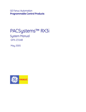
Ethernet PortsLAN1 connects to the uppermost RJ-45 connector. It is not switched. LAN2connects to the two lower RJ-45 connectors. They are switched internally.Record the IP Address of each LAN in the space provided (Figure 1).Each of the embedded Ethernet interfaces automatically senses the datarate (10 Mbps or 100 Mbps or 1 Gbps), communications mode (half-duplexor full-duplex), and cabling arrangement (straight-through or crossover) ofthe attached link.For improved performance, the two Ethernet LANs are serviced by adedicated microprocessor core. In addition, each Ethernet LAN is servicedby a dedicated Network Interface Controller (NIC). In this way, the servicingof the Ethernet ports is independent of the controller logic and I/Oscanning. This superior level of servicing is required at the highercommunications rates.Any of the embedded Ethernet ports may be used to communicate with thePME programming software using the Service Request Transport Protocol(SRTP, a proprietary Emerson protocol, used primarily for communicationwith the programmer).To establish Ethernet communications between PME and the CPE, Emersonrecommends inserting an ETM with a known IP address into the rack tostore a hardware configuration for the CPE330 with the desired IP address.10PACSystems RX3i 64 MB CPU w/Ethernet Quick Start GuideGFK-2941K
I P A ddress:S ubnetMas k:Gate way:C P E330 LAN1192.168.0.100255.255.255.0C P E330 LAN210.10.0.100255.255.255.00.0.0.00.0.0.0Figure 1: Typical Multi-Tier LAN ApplicationA typical application will take advantage of the two independent LANs. Thededicated LAN1 port will be used for communications with plant-level orsupervisory layers. The switched LAN2 will typically be used tocommunicate with devices within the manufacturing cell or process,including local HMI devices and micro-controllers.11PACSystems RX3i 64 MB CPU w/Ethernet Quick Start GuideGFK-2941K
Hardware InstallationInitial ChecksUpon receiving your RX3i equipment, carefully inspect all shippingcontainers for damage. If any part of the system is damaged, notify thecarrier immediately. The damaged shipping container should be saved asevidence for inspection by the carrier.As the consignee, it is your responsibility to register a claim with the carrierfor damage incurred during shipment. Emerson Automation Solutions willfully cooperate with you, however, should such action be necessary.After unpacking the RX3i equipment, record all serial numbers. Serialnumbers are required if you should need to contact Customer Care duringthe warranty period. All shipping containers and all packing material shouldbe saved should it be necessary to transport or ship any part of the system.Verify that all components of the system have been received and that theyagree with your order. If the system received does not agree with yourorder, contact Customer Care.Installation LocationThis product is intended for use with the RX3i system. Its components areconsidered open equipment (having live electrical parts that may be12PACSystems RX3i 64 MB CPU w/Ethernet Quick Start GuideGFK-2941K
accessible to users) and must be installed in an ultimate enclosure that ismanufactured to provide safety. At a minimum, the enclosure shall providea degree of protection against solid objects as small as 12mm (e.g. fingers).This equates to a NEMA/UL Type 1 enclosure or an IEC60529 IP20 ratingproviding at least a pollution degree 2 environment. For details aboutinstalling RX3i rack systems, refer to the PACSystems RX3i System Manual,GFK-2314.If you need technical help, contact Technical Support. For phone numbersand email addresses, refer to the back cover of this Guide.Installation in Hazardous AreasThe following information is for products bearing the UL marking forHazardous Areas or ATEX marking for explosive atmospheres:Class 1 Division 2 Groups ABCD 13This equipment is an open-type device and is meant to be installed inan enclosure suitable for the environment that is only accessible withthe use of a tool.Suitable for use in Class I, Division 2, Groups A, B, C and D HazardousLocations, or nonhazardous locations only.PACSystems RX3i 64 MB CPU w/Ethernet Quick Start GuideGFK-2941K
WA RNING - EXPLOSION HAZARD - SUBSTITUTION OF COMPONENTS MAYIMPAIR SUITABILITY FOR CLASS I, DIVISION 2. WA RNING - EXPLOSION HAZARD - WHEN IN HAZARDOUS AREAS, TURNOFF POWER BEFORE REPLACING OR WIRING MODULES.ATEX Zone 2This module must be mounted in an enclosure certified in accordance withEN60079-15 for use in Zone 2, Group IIC and rated IP54. The enclosure shallonly be able to be opened with the use of a tool.GroundingThe RX3i rack into which this product will be mounted must be groundedper the instructions provided in PACSystems RX3i System Manual, GFK-2314.Also, if an Energy Pack (IC695ACC402) is connected, its ground-strap mustbe grounded as described in PACSystems RX3i Energy Pack IC695ACC402Quick Start Guide, GFK-2939.14PACSystems RX3i 64 MB CPU w/Ethernet Quick Start GuideGFK-2941K
Module Start-upYou Will Need: 1An RX3i Universal Backplane: IC695CHS007, IC695CHS012 orIC695CHS016.This PACSystems RX3i CPU. This CPU occupies two backplane slots.An RX3i rack-mounted Power Supply Module and compatible powersource(AC1 or DC).A computer running PAC Machine Edition (PME) configuration andprogramming software. PME Version 9.70 SIM 16 or later supports allfeatures in this document.Ethernet cable for connecting the PME programmer computer to theRX3i CPU.Phillip’s head screwdriver.A very small slotted screwdriver (1.4 mm jeweler’s size).On lightly-loaded racks, use IC695PSA040H or later, or IC695PSA140D or later, otherwise powerup may be unsuccessful. Alternately, fill out the empty slots in the rack to draw more current.15PACSystems RX3i 64 MB CPU w/Ethernet Quick Start GuideGFK-2941K
Basic Installation StepsFor startup and configuration of the CPE330, complete the following steps.For full details on CPE330 operation, refer to the PACSystems RX3i & RSTi-EPCPU Reference Manual, GFK-2222 or later.1. Turn power off at the RX3i rack and install the CPE330 in a doubleslot which is CPU-compatible (refer to PACSystems RX3i SystemManual, GFK-2314 Chapter 3). Typically, the CPU is in the left-mostslot pair, or in the pair of slots to the right of the power supplymodule.2. If used, mount the compatible RX3i Energy Pack (IC695ACC402)within 3 feet of the CPU. The dedicated interconnect cable attachesto the underside of CPE330. Follow interconnect and groundinginstructions in PACSystems RX3i Energy Pack IC695ACC402 Quick StartGuide, GFK-2939. Secure the two retention flat-head screws with avery small slotted screwdriver.3. Set the pair of hook tabs at top rear of the CPU module into twoadjacent notches on the alignment rail of the RX3i rack backplane.This aligns the module with the intended slots in the main rack andwith the right-side connector of this pair.4. Swing the module down until the rear connector on the CPU moduleengages the mating backplane connector. Firmly engage theconnectors.5. Visually inspect the module to be sure it is properly seated.16PACSystems RX3i 64 MB CPU w/Ethernet Quick Start GuideGFK-2941K
6. Using a Phillip’s head screwdriver, secure the two captive M3 x 5 mmmachine screws into the matching threaded holes in the backplateof the RX3i I/O rack. The two screws are located at the bottom rearof the CPU module. Tighten.7. Apply power to the rack.Note: When the ACC402 Energy Pack is powered up, a period of time isrequired to charge it up to its operating level. During this time, theEnergy Pack will indicate this condition via its LEDs (refer toPACSystems RX3i Energy Pack IC695ACC402 Quick Start Guide, GFK2939).The CPE330 will begin its boot cycle once ACC402 is charged. Thistypically takes 90 seconds or less. In the event the ACC402 is faulty oris not communicating, CPE330 commences operation without theEnergy Pack.Redundancy ConfigurationPAC Machine Edition 8.60 SIM 8 or later may be used to create nativeCPE330 redundant applications when a rack-mounted IC695PNC001 is usedas the PROFINET Controller. If using the CPE330 Embedded PROFINETController, use PME 9.50 SIM 7 or later.17PACSystems RX3i 64 MB CPU w/Ethernet Quick Start GuideGFK-2941K
To enable redundancy in a CPE330 project, select the CPE330 target in thePME Navigator and use the Property Inspector to change the EnableRedundancy target property to True.PROFINET Controller ConfigurationPAC Machine Edition 8.60 SIM 13, PME 9.00 SIM 4 or later may be used toconfigure an Embedded PROFINET Controller in the CPE330 HardwareConfiguration on LAN 2.To enable the PROFINET Controller in a CPE330 project, select the CPE330 2target in the PME Navigator and open the Hardware Configuration. On theSettings tab, change the LAN 2 Mode to PROFINET. The PROFINET Controllernode description now displays that it is using LAN 2 as a submodule underthe CPE330.Compatibility with CPU320/CRU320/CPU315The CPE330 also serves as a drop-in replacement for the CPU320, CRU320,and CPU315 Controllers without the need to upgrade PME. To downloadprojects intended for the CPU320/CRU320 to a CPE330 with versions ofPME that do not support the CPE330, you must change the CPE330’scompatibility setting.2CPE330 release 8.90 or later is required for the embedded PNC feature.18PACSystems RX3i 64 MB CPU w/Ethernet Quick Start GuideGFK-2941K
To change the compatibility setting, perform the following operations:1.2.3.Power off the CPE330 and remove any USB stick that might be attached toits USB connector.Place the CPE330’s RUN/STOP switch in the STOP position.Hold down the RDSD UPLD button and turn power on to the CPE330.Continue to depress the RDSD UPLD button until the CPE330 powers upand displays one of the following patterns on the LEDs.CPU Status IndicatorsC P E330 LEDOnL ED StateC P U OKOn AmberFORC EOn AmberRUNOffRD S DOn RedOUT ENOffS YS FLTOn RedC P U OKOn AmberFORC EOn AmberRUNOn RedRD S DOffOUT ENOffS YS FLTOn Red19BlinkingOffOpe rating StateNormal mode. (Compatible with CPU320)CRU320 Compatibility mode.PACSystems RX3i 64 MB CPU w/Ethernet Quick Start GuideGFK-2941K
4.5.To toggle the compatibility setting, press the RDSD DNLD button. Thecompatibility indication will toggle between the Normal (CPU320) andCRU320 compatibility patterns each time the RDSD DNLD button ispressed.When the desired compatibility setting is displayed, press the RDSD UPLDbutton to save the setting and allow the CPE330 to continue its normalstartup procedures with the new setting. The setting is maintained over apower cycle and firmware upgrade.Note that with versions of PME that do not have native CPE330 support,only CPU320 projects can be stored to CPE330s that are in Normal(CPU320) compatibility mode and only CRU320 projects can be stored toCPE330s that are in CRU320 compatibility mode. Users of a CPE330 withPME version 8.60 SIM 8 or later do not need to change this compatibilitysetting if the project is converted to a CPE330 application. By factorydefault, the CPE330 is set to Normal (CPU320) compatibility mode.Migration of CPU315 applications to the CPE330 is possible with no upgradeto PME by converting them to a CPU320 application and storing the projectto the CPE330.Note that CPE330s with firmware versions 8.45 through 8.60 supportcompatibility with the CPU320 and CPU315 only. The compatibility settingusing the RDSD buttons is not supported for these firmware versions.Beginning with firmware version 8.70, CPE330s support compatibility withthe CPU320, CPU315, and CRU320 using the RDSD buttons to set thecompatibility mode.20PACSystems RX3i 64 MB CPU w/Ethernet Quick Start GuideGFK-2941K
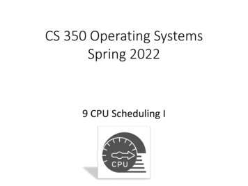
The compatibility setting may be viewed at any time using the CPE330’sfirmware update web page. When the compatibility setting is Normal(CPU320), the catalog number is listed as “IC695CPE330.” When thecompatibility setting is CRU320 compatibility mode, the catalog number islisted as “IC695CPE330 CRU320 Compatibility Mode.”Removable Data Storage Device (RDSD)The CPE330 user program and/or memory contents may be saved to a USBdevice via the RDSD UPLD pushbutton or loaded into the CPU from a USBdevice via the RDSD DNLD pushbutton. Similarly, data can be selected andsaved. In this way, an application may be cloned and copied from onedevice to another.Periodic MaintenanceReal-Time Clock BatteryThe CPE330 is shipped with a real time clock (RTC) battery installed (Figure2). Over time, this battery will need to be replaced. No action is r equiredduring initial installation.Should the RTC battery fail, the CPU date and time will be reset to 12:00AM, 01-01-2011 at start-up. The CPU operates normally with a failed or21PACSystems RX3i 64 MB CPU w/Ethernet Quick Start GuideGFK-2941K
missing RTC battery; however, the initial CPU time-of-day (TOD) clockinformation will be incorrect.Figure 2: RTC BatteryThere are no diagnostics or indicators to monitor RTC battery status. TheRTC battery has an estimated life of 5 years and must be replaced every 5years on a periodic maintenance schedule.For complete procedure, refer to Replacement of Real-Time Clock Batteryon CPE330 in PACSystems RX3i, & RSTi-EP CPU Reference Manual, GFK2222V or later.22PACSystems RX3i 64 MB CPU w/Ethernet Quick Start GuideGFK-2941K
Spare PartsIC690ACC001 Battery, Lithium BR2032-BA Coin Cell 3 V 190 mAh -40 Cto 85 CAdditional InformationPAC Logic Developer-PLC Getting StartedGFK-1918PACSystems RX3i & RSTi-EP CPU Reference ManualGFK-2222PACSystems RX3i & RSTi-EP TCP/IP Ethernet Communications User’sManualGFK-2224PACSystems TCP/IP Ethernet Communications Station Manager ManualGFK-2225PACSystems RX3i System ManualGFK-2314PACSystems RXi, RX3i & RSTi-EP Controller Secure Deployment GuideGFK-2830PACSystems RX3i Energy Pack IC695ACC402 Quick Start GuideGFK-2939PACSystems RX3i IC695CPE330 CPU Important Product InformationGFK-2942PACSystems RX3i & RSTi-EP CPU Programmer’s Reference ManualGFK-2950PACSystems HART Pass Through User ManualGFK-2929PACSystems Hot Standby CPU Redundancy User ManualGFK-2308PACSystems RX3i PROFINET IO Controller User ManualGFK-2571PROFINET I/O Devices Secure Deployment GuideGFK-2904PACSystems Memory Xchange Modules User’s ManualGFK-2300C Programmer’s Toolkit for PACSystems User’s ManualGFK-2259PACSystems RX3i Sequence of Events User ManualGFK-305023PACSystems RX3i 64 MB CPU w/Ethernet Quick Start GuideGFK-2941K
General Contact InformationPlease visit us for product support or updated product information:Online Technical Support and ditional mation-controlsAll Rights Reserved.We reserve the right to modify or improve the designs or specifications of theproducts mentioned in this manual at any time without notice. Emerson does notassume responsibility for the selection, use or maintenance of any product.Responsibility for proper selection, use and maintenance of any Emerson productremains solely with the purchaser. 2019 Emerson Electric Co.
Output scan is enabled. Off Output scan is disabled. FORCE On Amber Override is active on a bit reference. Off No Overrides active in I/O Reference Tables. RDSD On Green USB Device detected (No Activity) Blinking Green Port activity detected on USB Interface Off No port activity detected on USB Interface On Red RDSD Failure Blinking Red