Transcription
This Datasheet for theIC693ALG392High Density Analog Output (8 4576-ic693alg392.aspxProvides the wiring diagrams and installation guidelines for this GE Series 90-30module.For further information, please contact Cimtec Technical Support at1-866-599-6507sales@cimtecautomation.com
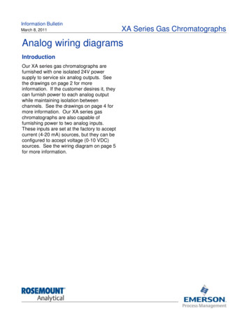
PACSystems RX3i and Series 90-30GFK-2557January 2009Series 90-30 Analog Output Module, Current/Voltage, 8 Channel, IC693ALG392RX3i Analog Output Module, Current/Voltage, 8 Channel, IC694ALG392MODULE 0KUSER SUPPLYIC694ALG392Q1Q2Q3Q4Q5Q6Q7Q8The 8–Channel Analog Current/Voltage Output module; IC69*ALG392, providesup to eight single-ended output channels with current loop outputs and/or voltageoutputs. Each output channel can be set up using the configuration software for anyof these ranges: 0 to 10 volts (unipolar)-10 to 10 volts (bipolar)0 to 20 milliamps4 to 20 milliampsEach channel is capable of converting 15 to 16 bits (depending on the rangeselected) of binary data to an analog output. All eight channels are updated every 8milliseconds.In current modes, the module reports an Open Wire fault to the CPU for eachchannel. The module can go to a known last state when system power isinterrupted. As long as external power is applied to the module, each outputwill maintain its last value or reset to zero, as configured.This module can be installed in any I/O slot of an RX3i system.Isolated 24 VDC PowerThe module must receive its 24 VDC power from an external source, which must beconnected directly to the module’s terminal block.
2Analog Output Modules, Current/Voltage, 8 Channel,IC693ALG392 and IC694ALG394GFK-2557Specifications: ALG392Number of Output ChannelsOutput Current RangeOutput Voltage RangeCalibrationUser Supply Voltage (nominal)External Supply Voltage RangePower Supply Rejection Ratio (PSRR)CurrentVoltageExternal Power Supply Voltage RippleInternal Supply VoltageUpdate RateResolution:1 to 8 selectable, single–ended4 to 20 mA and 0 to 20 mA0 to 10 V and –10 V to 10 VFactory calibrated to .625 µA for 0 to 20 mA; 0.5 µA for 4 to20 mA; and .3125 mV for voltage (per count) 24 VDC, from user supplied voltage source20 VDC to 30 VDC5 µA/V (typical), 10 µA/V (maximum)25 mV/V (typical), 50 mV/V (maximum)10% (maximum) 5 VDC from PLC backplane8 milliseconds (approximate, all eight channels)Determined by I/O scan time, application dependent.4 to 20mA: 0.5 µA (1 LSB 0.5 µA)0 to 20mA: 0.625 µA (1 LSB 0.625 µA)0 to 10V: 0.3125 mV (1 LSB 0.3125 mV)-10 to 10V: 0.3125 mV (1 LSB 0.3125 mV)Absolute Accuracy: *Current ModeVoltage ModeMaximum Compliance VoltageUser Load (current mode)Output Load Capacitance (current mode)Output Load Inductance (current mode)Output Loading (voltage mode)Output load CapacitanceIsolation, Field to Backplane (optical) and toframe groundPower Consumption /-0.1% of full scale @ 25 C (77 F), typical /-0.25% of full scale @ 25 C (77 F), maximum /-0.5% of full scale over operating temperature range(maximum) /-0.25% of full scale @ 25 C (77 F), typical /-0.5% of full scale @ 25 C (77 F), maximum /-1.0% of full scale over operating temperature range(maximum)VUSER –3 V (minimum) to VUSER (maximum)0 to 850 Ω (minimum at VUSER 20 V, maximum 1350 Ω atVUSER 30 V) (Load less than 800 Ω is temperaturedependent.)2000 pF (maximum)1H5 mA (2 K Ohms minimum resistance)(1 µF maximum capacitance)250 VAC continuous; 1500 VAC for 1 minute110 mA from 5 VDC PLC backplane supply315 mA from 24 VDC user supplyRefer to the PACSystems RX3i Systems Manual, GFK-2314, for product standards and generalspecifications. In order to meet the levels for RF Susceptibility specified in Appendix A of the PACSystemsRX3i System Manual, GFK-2314, when this module is present, the system must be mounted in a metalenclosure. In the presence of severe RF interference, accuracy may be degraded to 1% FS for current outputs and 3% FS for voltage outputs.
Analog Output Modules, Current/Voltage, 8 Channel,IC693ALG392 and IC694ALG3943GFK-2557CompatibilitySeries 90-30 PLC CPU: for CPU firmware versions 3.3 to 4.6, the module must be configured for 16 %I inputs or a Lossof Module Fault will occur. CPU firmware must be version 5.0 or later to configure the module for 8% I inputs.Hand-Held Programmer: Only Series 90-30 modules IC693ALG392 version C or earlier support the Series 90-30 Handheld Programmer. Series 90-30 modules IC693ALG392 version BD or later and RX3i modules IC694ALG392 (allversions) cannot be used with a Hand-held Programmer.Release G392-BBJanuary 2009Updated processor and D/A converter.IC693ALG392-BB or later is not compatible with a Series 90-30Hand-held Programmer.IC693ALG392-CFebruary 2005ATEX approval for Group 2, category 3 applications.IC694ALG392-AAJuly 2004Initial product releaseIC693ALG392-BOctober 1995CE certificationIC693ALG392-An/aInitial product releaseNew FeaturesWhen used in a PACSystems RX3i, modules IC693ALG392 version BD or later and IC694ALG392 version BB or latercan be field-upgraded using Winloader.Proficy Machine Edition displays the module firmware revision level for modules IC693ALG392 version BD or later andIC694ALG392 version BB or later in PACSystems RX3i targets.
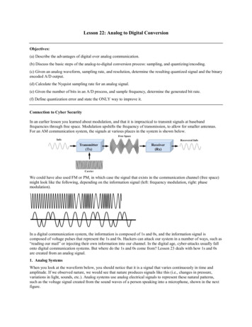
4Analog Output Modules, Current/Voltage, 8 Channel,IC693ALG392 and IC694ALG394GFK-2557Derating Curves: ALG392For maximum performance and module life, the module should be operated at maximum load resistance to offload heat.Module thermal deratings depend on the voltage level and the use of current and voltage outputs. The first two chartsbelow show the maximum ambient temperature for current-only modules at 30 VDC and at 26.5 VDC.Current Outputs OnlyAmbientTemperatureAmbientTemperature1200 ohm loads800 ohm loads601000 ohm loads6055500 ohm loads55250 ohm lo ads50250 ohm loadsShorted loads50shorted loads45500 ohm loads454040V USER 30V35V USER 26.5V35123456781Number of Active Channels2345678Number of Active ChannelsMixed Current and Voltage OutputsIn the example shown below, voltage channels have 2 K Ohm loads and current channels have shorted loads. Todetermine the maximum operating temperature for mixed current and voltage outputs, select the line in the chart belowthat corresponds to the number of voltage channels being used. For example, a module uses 2 voltage channels and 3current channels. The total channels are 5, and the maximum operating temperature is approximately 52.5 C:8 Channels VAmbient60Temperature ( C)6 Channels V554 Channels V502 Channels V4540VUSER 30V3512345678Active Channels Current and Voltage Mixed
Analog Output Modules, Current/Voltage, 8 Channel,IC693ALG392 and IC694ALG3945GFK-2557Current and Voltage Ranges and ResolutionIn the 4 to 20mA range, the module scans output data from the PLC so that 4mA corresponds to a count of 0, and 20mAcorresponds to a count of 32000. In the 0 to 20mA range, user data is scaled so that 0 mA corresponds to a count of 0and 20mA corresponds to 32000. In 0 to 20mA mode, a value up to 32767 provides a maximum output of approximately20.5mA. In current mode, the module also reports an open loop fault to the PLC.For voltage operation in the default unipolar mode (0 to 10 volts), data is scaled so that 0 volts corresponds to a countof 0 and 10 volts corresponds to a count of 32000. In this mode, a value up to 32767 creates an overrange output ofapproximately 10.24 volts.In the -10 to 10 volt range, data is scaled so that -10 volts corresponds to a count of -32000 and 10 volts correspondsto a count of 32000. In this range, output values from -32767 to 32767 result in an overrange of approximately -10.24volts to 10.24 volts.Scaling for both current and voltage ranges is shown below.320000 to 20mA RangeScaledoutputvalue4 to 20mA Range00204Current -32000 100Voltage (V), Unipolar ModeThe resolution per bit depends on the channel’s configured range:4 to 20 mA:0.5 µA0 to 20 mA:0.625 µA0 to 10 V:0.3125 mV-10 to 10 V:0.3125 mV-100Voltage (V), Bipolar Mode 10
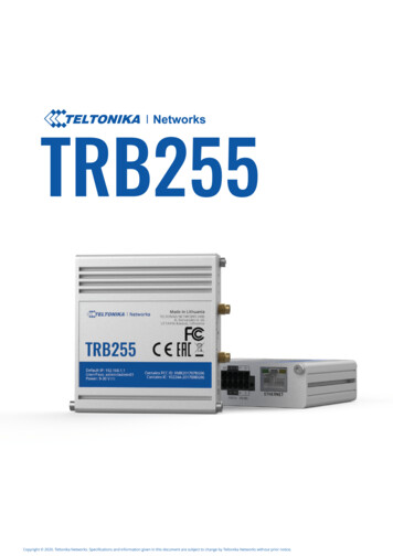
6Analog Output Modules, Current/Voltage, 8 Channel,IC693ALG392 and IC694ALG394GFK-2557Field Wiring: ALG392Field Wiring forCurrent Outputs24 VDC INTerminal1234567891011121314151617181920Signal DefinitionUser Supplied 24 VDC InputChannel 1 Voltage OutputChannel 1 Current OutputChannel 2 Voltage OutputChannel 2 Current outputChannel 3 Voltage OutputChannel 3 Current outputChannel 4 Voltage OutputChannel 4 Current outputChannel 5 Voltage OutputChannel 5 Current outputChannel 6 Voltage OutputChannel 6 Current outputChannel 7 Voltage OutputChannel 7 Current outputChannel 8 Voltage OutputChannel 8 Current outputVoltage CommonCurrent Common/User 24 VDC ReturnFrame ground connection for cable shields -(-)-)5-)-)7-)911IQ5(-)( )13IQ6(-)15IQ7(14( )-)16( )IQ8( )17181920(-)VQ2(-)VQ3(-)VQ4(-)VQ5( )12(-)VQ1( )10( )( )( )8( )Field Wiring forVoltage Outputs( )6( )IQ4(4( )IQ3(23IQ2(1( )IQ1(Terminals(-)VQ6( )(-)VQ7( )(-)VQ8VCOMFGNDOptional CableShield GroundThe diagram above shows connections for current and voltage outputs. Each channel can be configured to operate as avoltage output or a current output - not both simultaneously.LEDsThe Module OK LED indicates module status. The User Supply LED indicates whether the external 24 VDC powersupply is present and is above the minimum level. Both LEDs are powered from the 5 VDC backplane power bus.LEDOKIndicatesON:Module OK and configuredFlashing: Module OK but not configuredOFF:USER OKModule is defective or no 5V backplane power presentON:External power supply presentOFF:No user powerInstallation in Hazardous Locations EQUIPMENT LABELED WITH REFERENCE TO CLASS I, GROUPS A, B, C & D, DIV. 2 HAZARDOUSLOCATIONS IS SUITABLE FOR USE IN CLASS I, DIVISION 2, GROUPS A, B, C, D OR NON-HAZARDOUSLOCATIONS ONLY WARNING - EXPLOSION HAZARD - SUBSTITUTION OF COMPONENTS MAY IMPAIR SUITABILITY FORCLASS I, DIVISION 2; WARNING - EXPLOSION HAZARD - WHEN IN HAZARDOUS LOCATIONS, TURN OFF POWER BEFOREREPLACING OR WIRING MODULES; AND WARNING - EXPLOSION HAZARD - DO NOT DISCONNECT EQUIPMENT UNLESS POWER HAS BEENSWITCHED OFF OR THE AREA IS KNOWN TO BE NONHAZARDOUS
IC693ALG392-C February 2005 ATEX approval for Group 2, category 3 applications. IC694ALG392-AA July 2004 Initial product release IC693ALG392-B October 1995 CE certification IC693ALG392-A n/a Initial product release New Features When used in a PACSystems RX3i, modules IC693ALG392 version BD or later and IC694ALG392 version BB or later .