Transcription
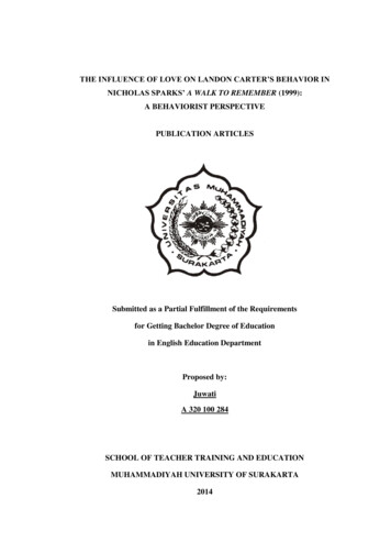
Carter ThermoQuad Information PageOverviewThe Carter ThermoQuad carburetor is an American designed and built carburetor, andwas original equipment on many American Chrysler V8 vehicles built during the 1970s.It was fitted to Australian manufactured Ford vehicles fitted with V8 gasoline enginesbuilt between 1977 and 1982. These years correspond to the Falcon models XC throughto XE.The Carter Thermo-Quad is a four-barrel carburetor with a spread bore throttle boreconfiguration. It was designed as an emissions capable carburetor that retained orsurpassed secondary throttle performance of earlier Carter carburetors, while deliveringsuperior primary fuel economy. The Thermo-Quad consists of three main sub-assemblies;an aluminum fuel bowl cover, a phenolic resin main body, and aluminum throttle baseassembly. The Thermo-Quad derives its name from the phenolic main body. Due to thematerial of the body, the carburetor bowl can stay 20 degrees cooler than an all-metalcarburetor in the same environment. Chrysler Corporation used the Thermo-Quad in carsand trucks 1971-1984. Carter also produced aftermarket versions.This guide is intended to provide information for identifying Thermo-Quad carburetorsand related items. It provides a basic history and basic descriptions of the carburetor andits subsystems. It is not intended as a full theory of operation manual or a repair manual.Service documentation should be consulted for repair procedures and service details. Thefactory service manuals provide good service procedures and theory for specific models.Other sources may be consulted for general repair and modification procedures as well astheory of operation. See the list of references for sources.This guide is written with carburetor 'swapping' in mind. Thus, certain items arediscussed with modification consideration (ie. emission subsystem disablement) with theintent for adapting a non-original carburetor and/or enhancing performance. Themodification and adaptation of the carburetors may present legal issues, so consider theinterest of any appropriate government(s).As fitted to Australian vehicles, the ThermoQuad is a two-stage four-barrel carburetorwith electrically activated automatic choke. It is a spread bore design, with secondarythroats twice the size of the primaries. See the picture below for an illustration of therelative size of the throttle bores. The secondary throttles are opened by a mechanicallinkage to the primary throttles, starting to open when the primary throttles are roughly3/4 open, with both primary and secondary throttles becoming fully open at the sametime. A spring loaded, vacuum operated air-door above the secondary throats preventsairflow through the secondaries until engine demands are sufficient to use the extra flow,thus aiding a smooth transition to wide-open throttle.
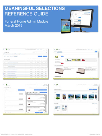
FeaturesThe Carter ThermoQuad features a plastic (phenolic resin, actually) main body (visible asthe dark center section in the above photographs). The main body contains the fuelreservoir, and the plastic construction is claimed to keep the fuel cooler than a metal bodywould, thus enabling more accurate fuel metering.The primary fuel metering system features mechanical and vacuum controlled meteringrods, which eliminate the need for a power valve circuit within the carburetor. Openingthe throttle mechanically raises the metering rods proportionally, thus richening themixture according to throttle position. Rod position, and hence mixture richness, isfurther controlled by engine vacuum, resulting in a fuel mixture that is always tailored toinstantaneous engine load.The carburetor is fully tunable. External idle mixture screws enable precise adjustment ofthe idle mixture. The primary circuit metering rods are adjustable and replaceable withoutdisassembly of the carb. The primary metering circuit also includes replaceable jets, andreplaceable metering rod step-up springs. Variation of step-up spring strength and preloadenables adjustment of the rate at which the mixture richens in relation to engine vacuumand hence load. The secondary metering circuit features replaceable jets. It is alsopossible to adjust the rate at which the secondary air-door opens, enabling activation ofthe secondary throats at higher or lower engine loads, depending on the needs of aparticular engine.The automatic choke mechanism features automatic choke activation, automatic chokepull-off, an initial throttle setting for starting, an automatically reducing throttle setting asthe engine warms up, and disabling of the carburetor secondary throats whilst the engineis cold. The choke activation temperature, pull-off rate, and cold-engine fast idle speedare all fully adjustable.Two timed-vacuum ports are provided on the front of the carburetor base.PERFORMANCE CONSIDERATIONS:Although not having a reputation locally as a performance carburetor, the CarterThermoQuad is nonetheless a sizeable four-barrel carburetor. The fully adjustable natureand spreadbore configuration enables tuning for maximum power at wide-open throttle,with excellent economy and emissions under cruise and idle conditions. AmericanThermoQuads are rated at between 800cfm and 1000cfm, which is more than enough foralmost any street driven engine, and these carburetors have been popular aftermarketfitments in that country. Hearsay has it that Australian ThermoQuads are rated at 600cfm,although I have not been able to confirm this. Even at 600cfm, this represents air-flow theequivalent of the most popular performance Holley four-barrel.
History and Description.General:The Thermo-Quad (TQ) was initially released for competition in 1969. Chryslerintroduced the TQ on the 1971 340. The first series of TQs including the 71 340 versionand the Competition Series TQs were air metered units unlike like the 72 and later TQswhich were solid (liquid) fuel metered. The Competition Series (CS) was available in 850cfm and 1000 cfm ratings. CS units use a manual choke and have a minimal amount ofexternal attachments compared to OEM production units. The CS was discontinued in themid-70s. Carter released the 9000 series in the latter 70s as replacement carburetors forChrysler and GM Quadrajet applications. The 9000 series was very similar to theproduction Chrysler Thermo-Quads.In 1972, the OEM Chrysler TQs changed to the solid fuel metering type. The TQcoverage was expanded to include the 400 engine. By 1973, all Chrysler 4-bblapplications were TQs (except some 413 truck models which continued to use a Holleycarburetor). As the years progressed, the TQ evolved to meet the continually tighteningemissions requirements. The changes were numerous. Many features were added ormodified externally and internally. The late 70s contained many variations for the variousgeographic regions, the various features included/excluded, and the range of applicationsand engines produced. Into the 80s, the TQ became more complex, but year-to-yearmajor variation lessened somewhat. In 1973, TQs received a port on the base for canisterpurge and a port on the main body to provide a venturi vacuum signal for EGRapplications. 1975 saw the introduction of the Idle Enrichment system, AltitudeCompensator on some models, and the Throttle Position Solenoid for the new catalyticconverter equipped cars.In 1976, Chrysler introduced Lean Burn ignition and the TQ was modified to produceand run on a very lean air/fuel mixture. An external idle stop switch and throttle positiontransducer were added. In 1978, the TQ bowl vent was modified with the addition of anelectric Bowl Vent solenoid. An additional rear base port for the vent hose replaced thebowl vent port. The fuel inlet moved to the rear center of the carburetor from the previousrear side location. Lean Burn became Electronic Spark Advance (ESA) in 1979. The verylean mixture idea was abandoned, but the electronic control of the ignition advance wasretained. Hidden mixture screws were a feature starting with some 1980 model TQs.1981 introduced a riveted cover for the choke pull-off linkage to prevent tampering andthe oxygen feedback solenoid on some models. Idle Enrichment and AltitudeCompensator was not used on feedback models. 82-84 did not change much more in amajor way. The canister purge was eliminated by 1984 in some applications and a powerbrake port was added to the rear base.
After 1984, Chrysler stopped using Thermo-Quads. Instead, the Rochester Quadrajet wasused through 1989 on cars and until 1988 in trucks when Electronic Fuel Injectionreplaced them. Carter continued to supply the fuel pumps for the Quadrajet equippedvehicles. Although Chrysler was the primary manufacturer to use the TQ, InternationalHarvester (IHC) used them in the late 70s and Ford used them in 1974.The Thermo-Quad was available with two primary throttle bore sizes, 1-3/8" and 1-1/2".Flow ratings (CFM) vary depending on the source, but the TQs with the 1-3/8" bores arelisted as 750-800 CFM and those with the 1-1/2" primary throttle bores are rated at 800850 CFM. All TQs have the 2-1/4" diameter secondary throttle plates. The primary boresize depended on application. In general, all 78 and later 318s and 360s and all 340s hadthe smaller bore. Earlier 360s varied depending on application, most 400s and all 440shad the large bore. The 9000 series have the small primary bore and were rated by Carterat 800 cfm. Later TQs (ie, Lean Burn and ESA applications, feedback systems) arequoted with less flow ratings, but this is due to the control of the carburetion system, notthe inherent flow capability of the basic carburetor. The internal metering is set for leanerrunning conditions for Lean Burn. Either bore size can be tuned to run well on mostengine combinations. The smaller bore offers a slight increase throttle response but lessoverall flow. The different bore sizing, ie. spreadbore, is an aspect that can lead toincreased fuel economy while delivering similar wide open throttle (WOT) performanceto an equivalent standard bore configuration. The adjustability of the TQ and thespreadbore configuration allows the use of a large CFM carburetor on a smalldisplacement engine.The TQ gets its name from the phenolic resin main body. This is "sandwiched" betweenthe aluminum bowl cover assembly and the lower throttle flange assembly. The plasticbody keeps the fuel 20 degrees cooler than an all metal carb in the same environment,leading to less percolation problems and increased performance due to a denser charge.The TQ is a metering rod based carburetor like other Carters (AFB, AVS, BBD). Theprimary jets are housed in the plastic body; the primary metering rods are suspended fromthe cover mounted step-up piston assembly into the jets (in the 71 TQ and the CS, theprimary jets are also housed in the cover). Engine vacuum (related to load) controls theposition of the metering rod in the jet, metering the fuel flow. The secondary jets aresuspended from the cover. Secondary flow is controlled by variable venturi effect in thesecondary bores. The TQ secondary throttle plates are controlled by direct mechanicallinkage, airflow is controlled by a secondary, spring tension resisted, air valve. The valveis further controlled and damped by the choke pull-off diaphragm.The OEM TQs have a divorced choke (73-up with electric assist in most applications),the 9000 series have an integral electric choke, and the CS was equipped with a manualchoke. All OEM TQs and later CS have screw-in jets. Early CS retained the jets via Orings.
Identification:To identify TQs, the model number is stamped on the lower left rear bolt flange. EarlierTQs also had a tag under one of the front bowl cover screws, later ones have a bar codesticker on the bowl cover with the Carter model and/or a Chrysler part number.International Harvester TQs also have a tag under a front bowl cover screw.Additional numbers will be found on the carburetor sections. These numbers are not usedfor TQ identification, but some can be used to relate one casting to the other (note thatparts with the same casting number may be machined differently). The upper bowl coverhas the casting number on the top, right of center rear: 6-XXXX (example: 6-2141, 62080, 6-2024). The bowl has the casting number molded on the bottom of the right bowlnear the front, it is difficult to see with the throttle base on the carb: 0-XXXX (example:0-2511A, 0-1823, 0-2709A). The throttle base has the casting number on the right upperside in a small recess: 1-XXXX (example: 1-2357, 1-2294, 1-2967. More numbers willbe found ink stamped, cast or stamped in various areas. Moreover, numbers are usuallystamped below the model number on the lower left rear bolt flange. The model numberconsists of four digits, usually followed by an 'S' (ie. 6318S). The model number is theprimary and documented identifier.The 71 OEM units can be identified externally by the mixture screws, which protrude atan angle from the base, in the same plane as the base, later units protrude perpendicular tothe base plane, but angle upwards from it. Note: some 1980 and later units have hiddenmixture screws. The Competition Series have raised pads on the upper bowl cover for alabel. Also, the CS have minimal external attachments, such as the lack of a PCV port.The mixture screws are similar to the 71 OEM TQs.The fuel inlet on the CS and the 78-84 OEM units was located in the rear center and the71-77 OEM and 9000 series have the fuel inlet on the right rear side. The aftermarket9000 series were available in 4 models: 9801, 9811, 9800, 9810. The 9801, 9811 haveChrysler linkage (9801/9811 is EGR capable). Note: later OEM TQs model numberstarted with a 9 as well, but are not to be confused with the aftermarket 9000 series.TQs with 1-3/8" primary throttle bore will have '2-315' stamped on the throttle plates. 11/2" units will have '2-314' stamped on the plates. All secondary plates are stamped with'2-312'.
Subsystems.This section briefly describes the primary Thermo-Quad subsystems that are readilyaccessible and the various attachments for emissions. For detailed theory of operation ofthe subsystems or general operating functions such as the low and high speed meteringcircuits, refer to the references listed in the References section, specifically the CarterThermo-Quad service manual. See the Service Parts Information section for details onparts and part numbers.Jets:jets are contained in the primary and secondary circuits, one for each barrel. EarlyCS units had press-in jets retained by o-rings. CS and 71 TQs have the primaryjets in the upper bowl cover. All other TQs have screw-in primary jets in the mainbody. All TQs have the secondary jets mounted in the upper bowl cover. All jetshave a part number prefix of 120-. 72 and later TQs usually have the part suffixstamped on the jet, primaries: 4XXX, secondaries: 5XXX (or 120-5XXX). TheXXX denotes the size, example: 4098 0.098", 5137 0.137". CS and 71 TQshave part number suffixes of 3XX or 3XXX.Metering rods and step-up:metering rods meter the fuel through the primary jets. They are essentiallycontrolled by engine vacuum and a mechanical link, step-up cam/lever, connectedto the primary throttle shaft. Many variations of metering rods were availablethrough the years. The depth of pre-76 models could be adjusted to tune, (primarily ), cruising condition flow via a screw adjustment. Some later modelsretained this feature, but starting in 1980 may have the adjustment locked via acollar. Metering rods have three steps for metering, economy, midrange, power.They are usually stamped with a part number, 75-XXXX or XXXX where theXXXX defines the step sizes. The CS and 71 TQs have numbers 16-XXX.Floats:TQs are a single fed, dual inlet, dual bowl carburetor. One bowl feeds each carbhalf, ie. one primary and one secondary. The dual bowl arrangement is containedin the phenolic main body. Dual floats and dual inlet valves are employed. EarlyTQs used brass floats. Later models (73-74 and later) use nitrophyl floats. AllOEM TQs are equipped with needle & seat number 25-1086 (0.0935" orifice).Accelerator pump:The accelerator pump is located on the left front and feeds from the left fuel bowl.The left side throttle bracket activates the pump. There is some strokeadjustability at the upper lever. The fuel is transferred via a plastic tube internallyto the squirter, which resides above the primary venturi. Later models have twoadjustment holes instead of three, and perform a two-stage pump that addsadditional fuel as the secondaries open. Three accelerator pump clusters(squirters) were available.
Secondary air valve:TQ secondary throttle plates are mechanically linked to the primary on the leftside. As the plates begin to open, the secondary air valve senses the opening andbegins to open to provide airflow, which starts fuel flow from the secondary jets.The initial opening and rate is determined by a counteracting tension spring insidethe cover. The opening is additionally regulated and dampened by the choke pulloff assembly. The air valve is contoured and the movement provides a variableventuri effect. A secondary fixed baffle is mounted below the air valve. Aprotruding tab limits total air valve movement. The counteracting spring tension isadjustable via a slot/lock screw on the left side to tune the rate. Carter designed aspecial tool to facilitate this adjustment. Some of the CS TQs used an adjustmentand lock screw arrangement similar to the AVS.Choke:OEM TQs use a divorced, manifold mounted choke. Exhaust crossover heatoperates the thermostatic spring contained in the choke well. Most 73-84 TQswere electrically assist heated. The electric control is via a small module mountedto the intake or right head. This unit times the assist based on temperature andtime and receives power from the ignition run circuit. 9000 series have an integralchoke assembly identified by the black, circular plastic thermostat housing. Thisunit is electrically controlled. CS units have a manual choke. Choke action isaccomplished via the choke plate in the top of the primary side.Mixture screws:Screws used through 11976 had a 20 degree taper at the seat. In 1977, this waschanged to 12 degrees to reduce adjustment sensitivity. Some 77-79 TQs alsocontained internal restrictors to limit adjustment. Plastic caps with tabs to limitadjustment were also installed on several models. Many 1980 and later TQs hadthe base redesigned to enclose the mixture screws so they could be 'capped' viaplugs after factory setting.Choke pull-off:On all TQ models. This performs the vacuum kick pull-off function for the chokeat initial cold engine start. It is also used to regulate and dampen secondary airvalve opening. Mounted on the right rear base under a mounting bolt and screw.Connects to the rear vacuum port, right, color code gold. The CS has thediaphragm for secondary air valve control only.Hot Idle Compensator:Some models are equipped with a compensator to allow extra air into the mixtureduring high heat conditions. If equipped, it is located on the bowl cover over thesecondary air valve. High temperatures can create an over-rich idle condition, andthis compensates for it, by allow extra airflow when it opens.Idle Stop Solenoid (ISS):71-76. Used to set the idle higher than the basic curb idle screw for emissionsreduction and to allow further closure of the throttle blades at engine shutdown toprevent 'dieseling' or 'run-on'. Mounts on a bracket retained by base mounting boltand screw on the right side for 72-76. 71 mounted to the left side of the intakeunder the carb linkage.
Exhaust Gas Recirculation (EGR) port:73-84, not used in some 76 81. Some located on the main phenolic body as a tapinto the venturi for vacuum signal. Venturi port is connected to a vacuumamplifier if used. Some models use a ported signal via a base port on the rightfront. Base ports color-coded black. Venturi ports are brass.Evaporative Control System (ECS) port:73-84. Used to purge the ECS charcoal canister of collected gas fumes from thebowl vent and fuel tank vent. Color-coded red.Idle Enrichment (IE) system:75-81. This is a drivability enhancement. It supplements the choke function byallowing an even richer mixture during the warm up period to improve drivability.This will appear as a small attachment on the front bowl cover that has a vacuumport that connects to a coolant temperature sensor (CCIE), then to manifoldvacuum with bleed. It will also be plumbed into the EGR delay timing system.Altitude Compensator or Alcomp (Alc):75-81. This is another drivability enhancement. It appeared on most Californiaand Federal high altitude cars. It appears as a small cylinder attached to the frontof the Idle Enrichment system at the front of the bowl cover. A small bellowsinside reacts to altitude changes and alters the airflow in the high speed meteringcircuit. This improves drivability and reduces emissions by maintaining a correctfuel/air mixture. Note: later vehicles may be equipped with a remote Alcompsensor (fender well) to signal the feedback solenoid controller to compensate.Bowl Vent (BV) solenoid:78-84. In an effort to completely capture all fuel bowl evaporative emissions, thestandard bowl vent was redesigned with a two way valve and holding solenoid atthe rear of the carburetor. When the engine starts, manifold vacuum pulls thevalve rubber 'puck' down, opening the bowl to the canister port. The solenoid isconnected to the ignition run circuit and holds the valve open during low vacuumperiods while running. When the engine is shutdown, the valve releases andreseals the float bowl. Connects to rear base port, color code gold.Ground Switch:76-84. This appeared with Lean Burn (LB). It signals the computer that thethrottle plates are at idle position. Later models with solenoid idle stop combinedthe functions. It is located on the bracket on the right front. A throttle shaftattachment contacts it.Throttle Position Transducer (TPT):776-81. This appeared with Lean Burn. It signals the position and movement rateof the throttle to the computer. It is attached via the same bracket as the GroundSwitch.Solenoid Idle Stop (SIS):81-84. Used to set the idle higher than the basic curb idle when additional heavyaccessory load (ie. rear window defogger, air conditioning) is placed on theengine. This mounts on a bracket on the right front.Dashpot:Some models, primarily trucks, may have a dashpot to slow throttle closing rate toreduce stalling. Mounted on a bracket on the left front.
Vacuum Pull-Off Choke:A few models may have an additional pull-off mounted on the left rear. Thisconnects to manifold vacuum via a control switch in the vacuum plumbing. Itprevents choke operation after engine warm up.Throttle Position Solenoid (TPS):75--later, some models. Mounts in the same place as the idle solenoids and is usedto delay full throttle closure at deceleration to prevent a momentary rich conditionthus protecting the catalytic converter(s).Vacuum Throttle Positioner (VTP):75--later, some models. Mounts in the same place and performs the same functionas the Throttle Position Solenoid. Also serves as a speed sensor.Pulse Solenoid, Oxygen Feedback Control (O2):81-84. Mounts on the front of the bowl cover (where the IE module mountedearlier). This solenoid is used to control the air/fuel mixture via varying dutycycle pulsing from the control computer based on feedback from exhaust, engine,and ambient sensors.Fuel bowl inserts:Some later models had an insert in the fuel bowls to reduce the bowl fuel volume.Choke pull-off cover:Many 81-84 models have a cover to prevent field adjustment of the pull-off.
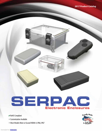
Port DiagramThis section contains a diagram and notes to identify the various hose port connections onthe Thermo-Quad. Different port configurations were used throughout the years. Thediagram is a representation of the throttle base, top view. It is drawn with all possibleports. The label notes identify the ports and their general usage. Some ports are containedin the bowl or bowl cover. These are also identified. The ports are labeled by(x).descriptions follow the diagram.FRONT-----(B) //(F) //------- ------- --- --- - ---- ----- O(A)(C)*(D)(E)O / / (G) / -------- --- / /\/\ / -- O O O O \/\/ -------- -------------------- /\/\ O O O O \/\/ -------------------- O (H) (I) (J) (K)(L)O --- -- --- - -- --- --- ----------------- \/ ----// //// (M)// -- --REAR----
(A) Distributor Vacuum Advance (black, 71-75, some 76-84), 5/32".(B) Idle Enrichment (IE) (gold, 75-81 some models), 5/32".(C) PCV (gold, 71-84), 11/32". * Note:: angled on 80-84 models.(D) Canister Purge (ECS) (red, 73-82),, 1/4".(E) EGR (gold) or Air Pump (blue), 5/332".(F) EGR venturi port (brass), 1/8", {located on phenolic float bowl}.(G) Bowl Vent (gold, 71-77), 11/32", (located on the upper bowl cover}.(H) Air Cleaner Heated Air Temp Sensor (black, 78-84), 5/32".(I) Power Brake Tube (gold, 81-84), 111/32".(J) Air Cleaner Heated Air Temp Sensor (black 71-77), 5/32", Bowl VentSolenoid Vacuum Tube (gold 78-84), 5/32".(K) Canister Bowl Vent Tube (gold, 78--84), 11/32".(L) Choke Pull-off (gold, 71-84), 5/322".(M) Choke Pull-off Diaphragm (natural,, 71-84), 5/32", {bolts to TQ base}Some other vacuum attachments were used, ie. Secondary pull-off and vacuumthrottle positioner.these (like item M) were external to the TQ.Choices and Adaptations:Choices:Chrysler used the TQ from 1971-1984. Ford used it in 1974 on some 460s andInternational Harvester used it in 74, 75, 79, 80 on 345/392 engines. The CS series wasavailable from 69- 73. The aftermarket 9000 series was available from 76- late 80s.The best OEM years to locate are 72-75. TQs from this period have the least emissioncontrol add-ons. The 71 OEM TQ performs well and have minimal emissionconsiderations. Due to its air-metered design, it is unlike the later TQs and few parts arestill available for it. The CS TQ was not intended for street use, thus it lacks provisionsfor many street engine items. Carter released the 9000 series in the latter 70s. It is a goodunit for most applications. It is the same design as the OEM TQ with minimal emissionsdevices. In 76, Chrysler introduced Lean Burn (ELB), which evolved into ElectronicSpark Advance (ESA). The 76-80 carburetors can be adapted for use in earlier vehicles.Many need idle screws and vacuum ports added. Most 78 and later TQs use a morecomplex bowl venting arrangement. The IHC carburetors are fairly simple like pre-76Chrysler TQs. 1980 TQs began receiving a pulsing solenoid as part of an oxygen sensorfeedback system to allow more computer control of the mixture. The TQs from thisperiod are the most complex and least desirable units.There were several internal metering and passage changes that occurred over the yearsfor emissions. Most TQs can be tuned to match most applications. The later carburetors,however, will need extra adaptation for earlier vehicles.
The Competition Series carbs should generally be avoided except for racing. Theaftermarket 9000 series were available in 4 models: 9801, 9811, 9800, and 9810. The9801, 9811 have Chrysler linkage (9811 is EGR capable). Note: later OEM TQs modelnumber started with 9 as well, not to be confused with the 9000 series. The 9801/9811 isthe preferred aftermarket TQ.Because TQs are out of production (since 1985), new parts are scarce except for commonservice items. Kits are available through Carter, Hygrade, KEM, etc. Floats, choke pulloffs, choke assemblies are also available. Tuning parts, ie. jets, rods, are no longeravailable new. Carter did make rod/jet kits ( Strip Kit ), but they are discontinued.Because replacement jets and rods are no longer available, tuning can be limited, unless asupply of used rods and jets is obtained. Many variations were used in the variousapplications over the years. Jets and rods can be modified. The carburetors are easy torebuild. TQs usually work well with just normal service adjustments.Adaptations:Note: for tuning basics and repair procedures see the References section for possibleinformation sources. This section considers basic and emission subsystem adaptationpossibilities.TQ on 'squarebore' intake:The TQ requires a spreadbore intake manifold. It can be adapted to a squareboretype via the use of an adaptor. Several companies make these (see Service Partssection). Some performance can be lost compared to a comparable spreadboreintake depending on the quality of the adaptor and the transition area. Vacuumleaks can be an issue too.1-3/8" vs. 1-1/2":The TQs have two different primary bore sizes. These units can be interchanged.The smaller bore will yield slightly better throttle response, but less overall flow.Jets/rods:The jets and metering rod’s can be changed on the TQ to tune its performance.Many sizes were available. See the Service Parts section for sizing information.Many later model TQs were lean on the primary side. Increasing primary jet sizeand/or reducing metering rod size will richen the primary side. Secondary jets canbe changed as well. If replacement units are not available, jets may be drilled toincrease size. Rods may be filed to reduce size. Solder and drilling/filing can beused to reverse this to some extent.Floats:Early TQs had brass floats. By 1975, all TQs used nitrophyl floats. Over time, thenitrophyl floats can absorb gas and sink, allowing fuel levels to be too high. Thefloats should weigh 7.4-8.0 grams. Carter no longer services brass floats, butseveral sources are available (see the Service Parts Information section).Accelerator pump clusters (squirters):The accelerator pump clusters were available in various sizes. Drilling may beused to increase the orifices to tune pump fuel delivery.
Mixture screws:The screws a
theory of operation. See the list of references for sources. This guide is written with carburetor 'swapping' in mind. Thus, certain items are discussed with modification consideration (ie. emission subsystem disablement) with the intent for adapting a non-original carburetor and/or enhancing performance. The modification and adaptation of the carburetors may present legal issues, so consider .