Transcription
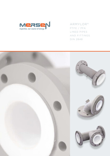
A R M Y LO R 2P T F E / P FALINED PIPESAND FITTINGSANSI B16.5
CONTENTEXPERTISE p.1MERSEN ANTICORROSION EQUIPMENT p.2PTFE / PFA POLYMERS p.3PTFE / PFA LINING p.4STEEL PARTS p.7LINED COMPONENTS p.9QUALITY CONTROL p.10INSTALLATION PROCEDURES p.11CODING SYSTEM AND REFERENCES p.13PRODUCTS p.14EXPERTISEMersen has an engineering team dedicatedto customer services.Our experts help study the best technical& economical solutions for your projects.This team can also assist our customers toproduce isometric drawings in order to create alist of fittings / components.The specification or data herein contained are only given for indication, withoutany undertakings whatsoever. Their publication does not suggest the matteris free of any rights whatsoever. Furthermore, due to constant evolution oftechniques and norms, we reserve the right to modify, at any time, thecharacteristics and specifications contained in this document.MERSEN refuses all and any responsibility concerning their use whateverthe purpose or application. Any copy, reproduction or information hereincontained, in whole or in part, made without MERSEN writtenconsent,is forbidden according to the laws of France and particularlythe lawnr. 92-597 of July 1st 1992 relating to the copyright.1
MERSEN ANTICORROSION EQUIPMENTThe Mersen AntiCorrosion Equipment activity is internationally recognized for its expertise in the designand manufacture of process equipment, manufactured from corrosion resistant materials (graphite, siliconcarbide, tantalum, zirconium, PTFE).Mersen also has an in-depth knowledge of the process technologies requiring our AntiCorrosion Equipmentand can provide offers from the basic equipment only, up to skid-mounted turn-key process packages.Since 1964, Mersen has been offering an exhaustive range of PTFE / PFA lined pipe and fittings especiallydesigned for conveying corrosive fluids in both the chemical and pharmaceutical industries.THE PRODUCT RANGE CONSISTS OF :PTFE / PFA lined pipe and fittingsPTFE bellows (expansion joints) and compensatorsPRESSUREVESSELS &COLUMNSHEAT UBECUBICANNULAR GROOVECOLUMNSILICONCARBIDEPTFEBLOCKSHELL & TUBEPLATE & FRAMEHCl, HBr AND H2SO4 SKID-MOUNTED UNITSTANTALUMSHELL & TUBECOILBAYONETCOLUMNZIRCONIUMTITANIUMNICKEL ALLOYSPRESSURE VESSELSERVICE CENTERSZIRCONIUM,TITANIUMAND NICKELALLOYSPTFE PIPING, COMPENSATORS, BURSTING DISCS,TANTALUM SMALL PARTSREPAIR, SPARE-PARTS, PREVENTIVE MAINTENANCE PTFE LINED PIPINGPTFE BELLOWTANTALUM SMALL PARTSGRAPHITE BURSTING DISC2
PTFE / PFA POLYMERSDEFINITIONAvailable lining materials for our product range are as follows :Virgin or anti-static* PTFE (Polytetrafluoroethylene), in accordancewith ASTM D4894 & 4895 standards.Virgin or anti-static* PFA (perfluoroalkoxy), according to ASTM D3307** standard.* Conductive black PTFE or PFA** Also on request according to DIN 53455 standardGENERAL CHARACTERISTICSValues indicated in the following table are given for virgin PTFE and PFA.These characteristics can vary depending on the material grades from the various suppliers,the transformation process and the batch.PROPERTIESUNITSPTFEPFAg/cm32.13 - 2.192.12 - 2.17% 0.010.03MPa20 - 4027 - 32%250 - 500300 - 500Modulus of elasticity under elongationMPa350 - 750650 - 700Modulus of elasticity under flexural stressMPa440 - 670590 - 70050 - 7260 - 65hardhardPhysicalDensityWater absorption : 24h thickness 3,2 mmMechanicalTensile strengthElongation at breakHardness shore D mandhodThermalFlame propagationMelting point C327 and 342300 to 310Other transitions C-90*, 123,* 27**-80*, 90*Maximum service temperature C-200/ 260-150/ 260Temp. of deflection under load (1.82 MPa) C50 - 6050Linear elongation coefficient105 / C10 - 2512Thermal conductivityW / m.K0.240.252.22.1ElectricalDielectric constant from 60 Hz to 107 HzVolume resistivityΩ.cm10181018Surface resistivityΩ10171017kV / mm.K36(1)80(2.3)Spark test (thick.mm)*amorphous phase, **crystal phaseRECEIVING INSPECTIONSMaterial certificates from the PTFE / PFA powder manufacturers are checked and identified with batch numbers. On request, FDA certificates (Food and Drug Administration) can be supplied.3
PTFE / PFA LININGMersen proposes 2 ranges of Armylor 2:Armylor 2 G to operate under pressureArmylor 2 V to operate under pressure and vacuumPTFE / PFA NOMINAL ,5The minimal thickness of the PTFE tube is equal to the nominal minus 10% - The thickness of the flare cannot be lower than the nominal thickness, minus 20%.TESTS ON PTFE / PFAPhysical and mechanical testsFor each manufacturing batch, Mersen checks the mechanical & physical properties.Values for elongation at break point and tensile strength, together with regularity of the graph confirmsthat the liner sintering has re-established the isotropy of PTFE, which guarantees a low level or permeability.Parallel directionPerpendicular directionStrain in %Strain in %4
PTFE / PFA LININGOptimal density ensures a balance between a low permeability level and a good distortion duringtemperature cycles.MECHANICAL PROPERTIESPHYSICAL PROPERTIESTensile strengthElongation at breakDensityPTFE ExtrudedVirginTest accordingto standard 21 N/mm2 (// Direction) 17 N/mm2 ( Direction)ASTM D4895 250% (// Direction) 200% ( Direction)ASTM D48952.14 - 2.19ASTM D7922.13 - 2.19DIN 53749AntistaticTest accordingto standard 21 N/mm2 (// Direction) 17 N/mm2 ( Direction)ASTM D4895 250% (// Direction) 200% ( Direction)ASTM D48952.13 - 2.19ASTM D7922.12 - 2.18DIN 53749PFAVirginTest accordingto standard 26 N/mm2ASTM D3307 300%ASTM D33072.12 - 2.17ASTM D7922.12 - 2.17DIN 53749AntistaticTest accordingto standard 26 N/mm2ASTM D3307 300%ASTM D33072.11 - 2.17ASTM D7922.11 - 2.16DIN 53749The results comply with the ASTM F1545 standardANTISTATIC PTFE / PFA ELECTRICAL PROPERTIESTransverse resistivity : 107 Ω based on the BS ISO 2878 : 2005 standardSurface resistivity : 108 Ω based on the BS ISO 14309 : 2011 standardVolume resistivity : 108 Ω based on the BS ISO 14309 : 2011 standard5
Thanks to Mersen’s expertise in lining technologies (PFA injection, extrusion of fine PTFE powders).Mersen has optimised its manufacturing processes and PTFE / PFA thicknesses in order to limit thepermeability rate.OPTIMIZING THE LINER THICKNESS - PERMEABILITYSEVERAL FACTORS HAVE AN INFLUENCE :Thickness of the liner is the most significant factor. The chart below shows the sharp decreaseof permeability versus thickness.Size of the ions or molecules : the Helium permeability curve shows the ability of a very smallmolecule such as helium to pass through the PTFE / PFA.Chemical nature of the product : any chemical similarity between the material passing through andthe material passed through increases permeability.Temperature and pressure: permeability increases with temperature and pressure.EXAMPLES OF PERMEABILITY CURVES :PTFE / PFA permeability curveLiner thickness (mm)Helium permeability PTFE / PFA curveTime (min.)6
STEEL PARTSCOMPONENTSThe table below shows the various steel components used for manufacturing our standard pieces.3.1 mill certificates in accordance with EN 10204 are available on request.ASTM compliant steel grades, low temperature or stainless steel grades can be supplied on request. Pleasecontact us for more information.PIPES / MENSIONALSTANDARDGRADEANSI B36.10ASTM 106 Gr BANSI B16.5ASTM A 105WELDEDCONSTRUCTIONELBOWSANSI B16.9/ANSIB16.28ASTM A 234 WPBANSI B16.5ASTM A 105WELDEDCONSTRUCTIONTEESANSI B16.10/ANSIB16.9ASTM A 106 Gr BASTM A 234 WPBANSI B16.5ASTM A 105ANSI B16.9ASTM A 234 WPBANSI B16.5ASTM A 105ANSI B16.5ASTM SA 516 Gr 60ASTM A 106 Gr BANSI B16.5ASTM SA 516 Gr 60ASTM A 106 Gr BANSI B16.5"ASTM A 105ASTM SA 516 Gr 60"SPOOLSCONCENTRIC&ECCENTRICREDUCERSREDUCING FLANGESPACERSWELDEDCONSTRUCTIONINSTRUMENT TEEANSI B36.107
WELDINGWelds are prepared by EN and ASME-qualified welders and processes such as GMAW, FCAW, GTAW andSAW. Quality of welds meets the requirements of the EN ISO 5817 level B standard.VENT HOLESTHE STEEL PARTS OF THE PTFE / PFA LINED FITTINGS ARE DRILLED WITH VENT HOLES IN ORDER TO :Prevent any back pressure between the metallic housing and the liner.Detect any leakage during pressure tests.Quickly detect any sign of corrosion.Spools with length below 500 mm have one 3 mm diameter vent hole in the middle of the piece. Those above 500 mm are fitted with two vent holes locatedabout 150 mm from each end. The fittings have at least one 3 mm diamander vent hole. Reducing flanges, blind flanges and spacers do not have any ventholes. In the case of particular specifications or thermal insulation piping, vent bosses can be welded to the vent holes.VENT BOSSESIf vent holes must be identified quickly or when the piping isthermal insulated, a coupling can be welded on tothe vent holes. In the case of different thermal insulationthicknesses, an extension stem can be screwed on to the coupling.ELECTRICAL CONTINUITYThe electrical continuity of lined piping can be ensured byconnecting each individual component together by usingconductors linked to earthing lugs.The latter are welded in the middle of the steel part for fittingsand spools below 500 mm long and at about 150 mm from theback side of each flange for spools above 500 mm long.Types A or B earthing lugs can be proposed on request.Standard materials are 304 or 316 stainless steel grades.Other materials can be supplied on request.PAINTINGThe standard coating is a 60 μm minimum thick zinc epoxy primer coating on sand blasted steel, inaccordance with the S.A 2.5 cleanliness level. Other surface preparations, undercoats or topcoats canbe applied on request.8
LINED COMPONENTSDIMENSIONAL TOLERANCESThe lined pieces and their dimensions are indicated in pages 15 to 30.All the lined pieces are built using the following tolerances NCE0 - 315 mm 0; -3 mm 0.5 315 - 1000 mm 0; -4 mm 0.5 1000 - 6000 mm 0; -5 mm 0.5 NB 1"-4" 0; -3 mm 0.5 NB 5"-8" 0; -4 mm 0.5 NB 10"-24" 0; -5 mm 0.5 DIAMETERSTolerance for PTFE / PFA : 5%TEMPERATURE CYCLE TESTSThe pieces tested undergo 100 alternate steam / cold water cycles, according to the ASTM F1545 standard.Steam is absorbed by the liner under the influence of both temperature and pressure.Vacuum resistance of the liner is then proved due to significant mechanical stresses causedby the sudden pressure drop combined with fast cooling.VACUUM "14"16" no vacuumARMYLOR GARMYLOR V4"Vacuum 2 Torr 200 C2 Torr100 CUnits : 760 Torrs 760 mmHg 1 bar 1 kg/cm2² 105 Pa 14.7 Psi9
QUALITY CONTROLINSPECTIONS AND TESTS PROGRAMMERSEN manufactures PTFE-lined piping and fittings compliant with the the European Pressure EquipmentDirective 2014/68/UE. Type agreements are awarded by Mersen’s Notified Body for the whole range ofARMYLOR products. In addition to assessments carried out by Third Parties and continuous internalaudits, a complete inspection and tests program is set during the entire manufacturing process :Raw material (fluoropolymers) : acceptance criteria at receiving inspections, physical properties ofthe liners monitored throughout the manufacturing process.Spark tests are performed on each PTFE and PFA-lined piece in the following conditions :voltage of 5000* E (E thickness of liner in mm) with a maximum of 25000 V.Dimensional and visual examination of the liners and steel parts :the weld aspect, the overall dimensions, the size of the collars, the liner thickness, the absence ofsurface defects and the painting thickness are checked.Non-destructive examinations are carried out when required by the applicable standardsor on request. RT and PT are performed by level II qualified personnel.Pressure tests : depending on the lining process, a hydrostatic or a pneumatic test is performed.A hydrostatic test is performed on pieces fitted with vent holes, injected or produced from tubes.TRACEABILITY AND MARKINGIN ADDITION TO THE INSPECTIONS AND TESTS PROGRAM, A FULL TRACEABILITY SYSTEM OFMATERIALS IS IMPLEMENTED :Steel parts : a coded marking system with unique traceability to the mill certificates is used. Markingtransfers by Mersen qualified personnel are approved by Mersen’s Notified Body.Finished product : in addition to the identification of label sticked on each item, the following information is stamped:the applicable standardthe lining materialthe manufacturing year and monththe CE mark and Notified Body Number (when applicable)the serial numberTraceability of documents : total traceability is ensured with the same method for both steel andlining materials.Serial numberOrder number Manufacturing numberCE symbol Notified Bodynumber (when applicable)10
INSTALLATION PROCEDUREInstallation and maintenance instructions are provided in the user’s manual delivered with the products.Specific items are highlighted here after.PRECAUTIONSThe lined steel components are delivered with wooden or plastic blanks installed to protect the PTFE / PFAflange faces. Remove these protective blanks when the components are about to be connected only : theyshall be refitted after each inspection and when the piece is withdrawn from the installation. Once the blankshave been removed, the greatest care is required : no contact with the ground, absence of any sharp objectthat could damage the liner. Never weld on lined parts.CLEANINGFlared surface must be carefully cleaned prior to connection.BOLT TIGHTENINGThe assembly of PTFE / PFA lined components does not require any gaskets except when materials of different natures are being coupled or during successive assembling and dismantling operations.TIGHTENING BOLTS :Insert the washers.Clean and grease the bolts.Tighten nuts by hands.Tighten each bolt using a torque wrench,keeping to the torque values specifiedin the table beside.Cross-tightening as with any flange connection.Tightening torque values are given for PTFE / PFA andmay vary depending on greasing and the condition ofthe nuts and bolts.Values are given for Ansi 150 lbs flanges. They are indicated for room temperature and must always bechecked in cold conditions, after 24 hours of operation,then checked periodically.THE TIGHTENING TORQUE VALUESINDICATED BESIDE APPLY TO :Class 8.8 steel nuts(resistant to 800 N/mm2 rupture,elasticity limit of 640 N/mm2).0.12. nut friction "1/237020''20x1"1/837024''20x1"1/4530
BOLT LENGTHSThe table below specifies the recommended lengths of threaded stems for the various assemblies.FIXED F. / FIXED F.LOOSE F. / LOOSE F.FIXED F. / LOOSE F.THE DIMENSIONS INDICATED REFER TO :A tightening torque equal equal to 1/3 the diameter of the threaded stems.A nut height equal to the diameter of the threaded stems.VENT HOLESVent holes must not be obstructed by thermalinsulation or painting. Where thermal insulationis fitted, vent extensions should be provided.When pipes are operated for the first time,air or water trapped inside at the momentof assembly may escape through the vent holes.It is recommended, during periodic inspection,to check that no trace of leakage is visiblearound the vent holes. The latter also act ascorrosion indicators.NBL1mmL2mmL3mmNB 1/2''759585NB 3/4''8010090NB 15NB 3''110140125NB 4''110140125NB 5"115145135NB 6''125165145NB 8''135175155NB 10''150195175NB 12''155205175NB 14''170220195NB 16''175225195NB 18''185235215NB 20''195245220NB 24''205260230NB 1NB 1NB 2''NB 2WEIGHTThe weight (kg) of each piece is indicatedon the corresponding tables. Due to the variousconstruction methods, the weights are typical valuesonly. The tolerance is /- 10%.SUPPORTSElements must be supported using collars that are notwelded on the lined piping. Never weld on lined parts.However, supporting elements may be welded prior tolining.121/2"
CODING SYSTEM AND REFERENCESEach element has its own unique reference which allows its identification.This reference is composed on 16 alphanumeric characters. In some cases, the character can be «-» if refersto standard. The references that are mentioned in the dimensional tables are the standard ones.DIMENSIONRANGEPIECES TYPENB LOOSEFLANGESSTEEL SHELLPARTICULARITYD DIN- G (PRESSURE)L PIPE LENGTH IN MM1, 2, 3, 4- STANDARD- STANDARDA ANSIV STANDARD(PRESSURE &VACUUM)C ELBOW ANGLER LOWTEMPERATURESTEELA SUPPORT LEGX STAINLESSSTEELB COUPLINGC SUPPORT LEG NLININGDNCONSTRUCTIONLINING PROCESS1 PN10- VIRGINSTANDARDSEE TABLEUNDER- STANDARD- PASTEEXTRUSION2 PN 20/150LBST TRANSFERMOLDINGA ANTISTATIC3 PN "M1" to eachproduct
PRODUCTS DATA SHEETSDIN FLANGES ANSI 150LBS AND PIPES p.15FLANGED SPOOLS p.16ELBOWS p.17EQUAL TEES p.18REDUCING TEES p.19-20CONCENTRIC & ECCENTRIC REDUCERS p.21REDUCING FLANGES p.22-24INSTRUMENT TEES p.25CROSSES p.26SPACERS p.28SPECTACLE BLINDS p.29BLIND FLANGES & LATERAL TEES p.3014
ANSI 150 LBS FLANGES AND TUBESDIMENSIONAL TOLERANCESEntire flanged products range can be equipped with loose or fixed flanges on request.DIAMETERSNBDdx*DRILLING ANSI150LBSTHICKNESSkb1b2b3b4mm mm mm mm mm mm mm1/2''Flange (front view)89313/4''991''1081''1/211.19.510holesSTEEL 269.0 12.711.1124x161/226.72.9476079.4 /248.33.72''1528792120.6 19.017.4144x205/860.33.93''191117127 152.4 23.8 22.2164x205/888.95.54''229150157 190.5 23.8 22.2168x205/8114.36.06''279203216 241.3 25.4 23.8188x233/4168.37.18''34325527028.6 27.0208x233/4219.18.210''406311324 361.9 30.2 28.62212x267/8273.09,312''485365381 431.8 32.731.12412x267/8323.89,514''53539341334.9 33.32512x291355.69,516''59745047036.5 34.92516x291406.49,518''635514533 577.8 39.738.12516x321 1/8457.29,520''69956558442.9 41.32520x321 1/8508.09.524''81366669247.6 46.02520x351 1/4609.89.5Welding neck type W (Fixed)* Tolerance 5%Slip-on Type P (Fixed)Collar slip-on type P (loose)15Collar slip-on type W
FLANGED SPOOLSLININGVIRGIN PTFE :NB 1/2’’ – NB 24’’ANTISTATIC PTFE, C4 A :NB 1/2’’ – NB 16’’Standard construction: 1 fixed flange, 1 loose flangeNBPairflangeskg/m weightREFERENCEL min. L max. For vacuum thickness, L max 4500 and xxx length in mm.Type P constructionType W construction16
ELBOWSLININGVIRGIN PTFE : NB 1/2’’ – NB 24’’ANTISTATIC PTFE, C4 A : NB 1/2’’ – NB 16’’Standard construction :1 fixed flange 1 loose flange up to NB 6’’2 fixed flanges from NB 8’’ up to NB 24’’L (mm)NBREFERENCEWeight (kg)α 90 α 45 α 60 α 30 90 45 60 30 9402320550212A2--C?--B* 2 parts or 3 parts construction? : Angle in degree : 90, 45, 60 or 30The 30 and 60 elbows are notincluded in theANSI B 16.5 standard171314151516Special angle available on request
EQUAL TEESLININGVIRGIN PFA : NB 1/2’’ – NB 4’’ANTISTATIC PFA : NB 1/2’’ – NB 4’’, C4 AVIRGIN PTFE : NB 5’’ – NB 24’’ANTISTATIC PTFE : NB 5’’ – NB 16’’, C4 AStandard construction :1 fixed flange on nozzle 2 loose flanges on body up to NB 6’’3 fixed flanges from NB 8’’ up to NB 24’’L1mmWeightkg1/2''653/4''NBConstruction in 1 partConstruction in 2 partsREFERENCE123456789101112 13 14 15 W16''*381266A2--TE---X18''*419308A2--TE---Y*2 parts construction18
REDUCING TEESLININGVIRGIN PFA : NB 3/4’’ – NB 4’’ANTISTATIC PFA : NB 3/4’’ – NB 4’’, C4 AVIRGIN PTFE : NB 5’’ – NB 24’’ANTISTATIC PTFE : NB 5’’ – NB 24’’, C4 ANB1Standardconstruction :1 fixed flange onnozzle 2 looseflanges on body upto NB 6’’3 fixed flangesfrom NB 8’’ up toNB 24’’3/4''1''1''1/22''3''4''Construction in 1 part6''*Construction in 2 789 10 11 12 13 14 15 162.0A 2V-TR---892.9A 2V-TR--- K H 23/4''893.1A 2V-TR--- K1/2''1024.6A 2V-TR--- M H 23/4''1024.8A 2V-TR--- M J1''1025.2A 2V-TR--- M K 21/2''1146.8A 2V-TR--- N H 23/4''1147.0A 2V-TR--- N1''1147.4A 2V-TR--- N K 211/2 ''1148.2A 2V-TR--- N M 21''14013.5A 2V-TR---P K11/2 ''14014.3A 2V-TR---P M 22''14015.4A 2V-TR---P N 21''16519.3A 2V-TR--- Q K11/2 ''16520.2A 2V-TR--- Q M 22''16521.2A 2V-TR--- Q N 23''16523.9A 2V-TR--- Q P21''20330.8A 2V-TR---S211/2 ''20331.7A 2V-TR---S M 22''20332.8A 2V-TR---S N 23''20335.6A 2V-TR---S4''20337.9A 2V-TR---S Q 21''22950.7A 2V-TR---T11/2 ''22951.6A 2V-TR---T M2''22952.7A 2V-TR---T N3''22955.5A 2V-TR---T4’’22957.8A 2V-TR---T Q6''22961.7A 2 V-TR---TJH 2JJKP222222KPS*2 parts construction19
LININGREDUCING TEESNB1Standardconstruction :1 fixed flange onnozzle 2 looseflanges on body upto NB 6’’10''*12''*3 fixed flangesfrom NB 8’’ – NB24’’14''*16''*Construction in 2 parts18''*20''*24''*VIRGIN PTFE : NB 6’’ – NB 24’’ANTISTATIC PTFE, C4 A : NB 6’’ – NB 16’’Weightkg123456REFERENCE7 8 9 10 VU4''356145A2--TR---W TR---BY12 13 14 15 16*2 parts construction20
CONCENTRIC & EXCENTRIC REDUCERS11/2"LININGVIRGIN PTFE/PFA :NB 3/4’’ – NB 24’’ANTISTATIC PTFE/PFAC4 A : NB 3/4’’ – NB 16’’Standard construction :Fixed flange/ 1 loose flange2''3''4''6''8''10"Concentric reducer12''14"16"Eccentric K111/2 ''1275.74.6A2V-R?---NM111/2 ''152207.2A2V-R?---PM12''152148.2A2V-R?---PM111/2 --R?---ZY20''61051226A2--R?---BZ2113 14 1516? E : Eccentric Reducer1L1mmNB2( ) Dimension non available in eccentric reducer ? C : C : Concentric ReducerNB1
LININGREDUCING FLANGESNB13/4''11''1/22''3''4’’NB2ØDmmbVIRGIN PTFE / PFA : NB 3/4’’ – NB 3’’ANTISTATIC PTFE/PFA, C4 A : NB 3/4’’ – NB 3’’NB1NB2Holes boltHoles boltØ k1mmnbØUNCØ k2mmnbUNCREFERENCETypeWeightkg123456789 10 11 12 13 14 15 *12735 98.44x1/2''60.34x1/2''B4.1A2V-BR--- M H3/4''*12735 98.44x1/2''69.84x1/2''B4.0A2V-BR--- M1''12735 98.44x1/2''79.44x1/2''B3.9A2V-BR--- M K1/2''15235 120.64x5/8''60.34x1/2''B4.8A2V-BR---NH3/4''15235 120.64x5/8''69.84x1/2''B4.8A2V-BR---NJ1''15235 120.64x5/8''79.44x1/2''B4.7A2V-BR---NK11/2 ''*15235 120.64x5/8''98.44x1/2''C4.5A2V-BR---N M1/2''19035 152.44x19M1660.34x1/2''A6.7A2V-BR---PH3/4''19035 152.44x19M1669.84x1/2''A6.6A2V-BR---PJ1''19035 152.44x5/8''79.44x1/2''B6.5A2V-BR---PK11/2 ''19035 152.44x5/8''98.44x1/2''B6.2A2V-BR---PM2''19035 152.44x5/8'' 120.64x5/8''C6.0A2V-BR--- P N1/2''229 45 190.58x19M1660.34x1/2''A11A2V-BR---Q H3/4''229 45 190.58x19M1669.84x1/2''A20A2V-BR---Q1''229 45 190.58x19M1679.44x1/2''A11A2V-BR---Q K11/2 ''229 45 190.58x19M1698.44x1/2''A11A2V-BR---Q M2''229 45 190.58x5/8'' 120.64x5/8''B10A2V-BR---Q N3''*229 45 190.58x5/8''4x5/8''B10A2V-BR---QTapped hole / through holetype A152.4Tapped holetype B22JJPTapped holes on center-line/off center-line type C
LININGVIRGIN PTFE/PFA : NB 4’’ – NB 10’’ANTI STATIC PTFE/PFA, , C4 A :NB 4’’ – NB 10’’NB1NB16''8''10''12''NB2ØDmmbmm Ø k1mmNB2HolesnbØTapped hole / throughhole type AREDUCING FLANGESUNCØ k2mmREFERENCEHolesnbUNCTypeWeightkg123456789 10 11 12 13 14 15 161''27945 241.3 8 x2279.4 4 x1/2''A17A 2 V- B R--- S K1'' 1/227945 241.3 8 x2298.4 4 x1/2''A17A 2 V- B R--- S M2''27945 241.3 8 x224x5/8''A17A 2 V- B R--- S N3''27945 241.3 8 x3/4''4x5/8''B16A 2 V- B R--- S4''27945 241.3 8 x3/4''8x5/8''C15A 2 V- B R--- S Q1''343458x2279.4 4 x1/2''A25A 2 V- B R--- T K1'' 1/2343458x2298.4 4 x1/2''A25A 2 V- B R--- T M2''343458x224x5/8''A25A 2 V- B R--- T N3''343458x224x5/8''A24A 2 V- B R--- T4''343458x228x5/8''A23A 2 V- B R--- T Q6''343458x241.3 8 x3/4''B20A 2 V- B R--- T1'' 1/24064512 x 25.598.4 4 x1/2''A34A 2 V- B R--- U M2''4064512 x 25.54x1/2''A34A 2 V- B R--- U N3''4064512 x 25.54x1/2''A33A 2 V- B R--- U P4''4064512 x 25.58x5/8''A33A 2 V- B R--- U Q6''4064512 x 25.5241.3 8 x3/4''A30A 2 V- B R--- U S*8''4064512 x8x3/4''B27A 2 V- B R--- U T2''4835012 x 25.54x1/2''A55A 2 V- B R--- V N3''4835012 x 25.54x1/2''A54A 2 V- B R--- V P4''4835012 x 25.58x5/8''A54A 2 V- B R--- V Q6''4835012 x 25.5241.3 8 x3/4''A49A 2 V- B R--- V S8''4835012 x 25.58x3/4''A44A 2 V- B R--- V T*10''4835012 x12 x7/8''B43A 2 V- B R--- V U3/4''7/8''7/8' '23PPS
LININGREDUCING FLANGESNB114''16''18''20''24''ANTISTATIC PTFE/PFA, C4 A : NB 10’’ – NB 24’’NB1ØDmmØ k1bmm mm nb6''533508''53310''NB2VIRGIN PTFE/PFA : NB 10’’ – NB 24’’NB2Holes boltØUNCØ k2mmHolesWeightTypekg1nbUNC12 x241.3 8 x3/4''A5012 x8x3/4''5335012 x361.9 12 x12''5335012 x8''5975010''59712''REFERENCE2346789 10 11 12 13 14 15 1660A 2-- B R--- W SA56A 2-- B R--- W T7/8''A53A 2-- B R--- W U431.8 12 x7/8''B50A 2-- B R--- W V16 x8x3/4''A75A 2-- B R--- X T5016 x361.9 12 x7/8''A71A 2-- B R--- X U5975016 x431.8 12 x7/8''A67A 2-- B R--- X V14''5975016 x1''B64A 2-- B R--- X W10''63550 577.8 16 x 31.7361.9 12 x7/8''A78A 2-- B R--- Y U12''63550 577.8 16 x 31.7431.8 12 x7/8''A75A 2-- B R--- Y V14''63550 577.8 16 x12 x1''A73A 2-- B R--- Y W16''63550 577.8 16 x16 x1''B71A 2-- B R--- Y X*6''6985020 x 31.7241.3 8 x7/8''A124A 2-- B R--- Z S*8''6985020 x 31.78x7/8''A114A 2-- B R--- Z T10''6985020 x361.9 12 x7/8''A207A 2-- B R--- Z U12''6985020 x 31.7431.8 12 x7/8''A98A 2-- B R--- Z V14''6985020 x 31.712 x1''A93A 2-- B R--- Z W16''6985020 x 31.716 x1''A88A 2-- B R--- Z X18''6985020 x1''1/8 577.8 16 x1''1/8B83A 2-- B R--- Z Y18''8135020 x 35577.8 16 x1''1/8A80A 2-- B R--- B Y20''8135020 x 3520 x 1''1/8A78A 2-- B R--- B Z1''1''1''1/212 xTapped holes type B5Tapped holes on center-line/off center-line type C24
INSTRUMENT TEES1''1''1/2LINING2''VIRGIN PFA :NB 1/2’’ – NB 20’’3''ANTISTATIC PFA,C4 A : NB 1/2’’ – NB 16’’VIRGIN PTFE :NB 24’’4''6''NB2LH Weightmm mmkg1/2''50893/4''501''5012''14''2345678910 '' PI---QJ1''501657.0A2V-PI---QK1'' 1/27516512A2V-PI---QM1/2''50 2038.9A2V-PI---SH3/4''50 2039.0A2V-PI---SJ1''50 20310A2V-PI---SK7520315A2V-PI---SM2''90 20316A2V-PI---SN1/2''50 22910A2V-PI---TH3/4''50 22910A2V-PI---TJ1''50 22910A2V-PI---TK7522916A2V-PI---TM2''90 22917A2V-PI---TN1''50 27924A2V-PI---UK7526A2V-PI---UMN1'' 1/22792''90 27927A2V-PI---U1''50 30526A2V-PI---VK7530529A2V-PI---VM2''90 30530A2V-PI---VN1''50 35641A2--PI---WK7544A2--PI---W M1'' 1/21'' 1/23562''90 35645A2--PI---W1''5038146A2--PI---XK1'' 51A2--PI---YK1'' 1/27541954A2--PI---YM2''9041955A2--PI---YN1''50 45760A2--PI---ZK7545763A2--PI---ZM2''90 45764A2--PI---ZN1''100 55969A2--PI---BK*24'' 1'' 1/2 150 55972A2--PI---BM73A2--PI---BN16''18''*20'' 1'' 1/22''150 559Fixed flanges2512 13 14 15 16H1/2''1''1/210''11.93/4''1'' 1/28''REFERENCEN* Assembly only possible using 4 bolts ** In 2 partsNB1
CROSSESLININGVIRGIN PFA : NB 1/2’’ – NB 4’’ANTISTATIC PFA : NB 1/
THE STEEL PARTS OF THE PTFE / PFA LINED FITTINGS ARE DRILLED WITH VENT HOLES IN ORDER TO : Prevent any back pressure between the metallic housing and the liner. Detect any leakage during pressure tests. Quickly detect any sign of corrosion. Spools with length below 500 mm have one 3 mm diameter vent hole in the middle of the piece.

