Transcription
Smart Park:A Senior Design Project For the Wireless CommunicationsCapstoneBy:Patrick OliveroChris CherinJoluis Castellanos
Table of Contents:1. Motivation2. Existing Solutions3. Goals and System Requirements4. Hardware5. Networking6. Software7. Testing8. What’s Next?
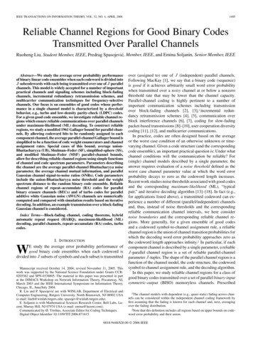
1. MotivationA parking deck is a symbol of efficient use of limited space to provide the most parking spots in agiven area. As you add more and more spots, however, it becomes increasingly difficult for a driver tofind the closest spot. This heightened difficulty necessitates driving in circles around the parking deckand looking for a spot all while decreasing our focus on safely driving in order to race in hopes of beatingsomeone else. In today’s world, the word “smart” is used to describe everything from cellphones tohomes which all feature more communication and interactivity between the user and the product. If ahome can be “smart” why can’t a parking garage? This is the question our group has posed and it is aquestion we feel we have solved with a system we call “Smart Park”.2. Existing SolutionsOur group is not alone in our quest to create a more interactive parking experience and thereexist systems already out there that attempt to tackle in many ways, each with pros and cons. One suchsystem would be the robotic garage. The concept of the robot garage is to fully automate the placementof a car in an efficient manner without the aid of the driver. All that is required of the driver is that theydrive up to the elevator or robotic stand at the entrance to the facility and then exit the vehicle. Sensorsare used to confirm that there are no passengers left in the vehicle and then machines move the vehicleinto a storage area.Fig. 1. Computer generated model of a robotic parking structure (left) and a real world example of onesuch system (right)
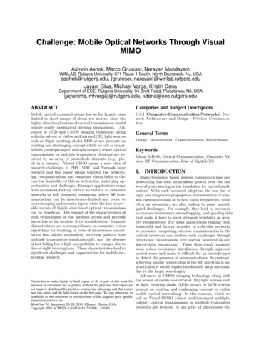
This system has its merits, including being able to use less space to store vehicles, as well asisolating vehicles from potential break-ins and theft. That isolation can also be a major issue. What ifonce out and the vehicle is stowed away, the driver remembers they may have left something in the caritself? Would the garage waste energy getting the car back for the driver to retrieve the item in questionthen return it back once more to its holding area? Also these robotic garages require large, complicated,and expensive machines in order to operate. This point is made clear when comparing the cost per spotof a conventional garage (about 15,000) with that of a spot in a typical automated garage (around 30,000). While machines like the ones used by the company, Robotic Parking System, use componentsrated with L10 lifetimes of 40,000 hours, this number can easily decrease with heavy usage as well assimply fail altogether as was the case several times with the nation’s first automated garage in Hoboken,NJ. There are many documented instances from 2002 thru 2007 of cars being trapped when the systemcould not retrieve them as well as incidents where vehicles were actually dropped by the machinery.Overall this system, while a promising idea, is costly both in the initial capital required to build thegarage and in the upkeep of having staff on hand at all times to maintain the machines that are criticalto the workings of the system itself.Another example of a similar system would be systems that use embedded sensors or wires to detectthe status of a parking spot. These systems look at their embedded nature as a means of integration intothe parking garage while avoiding exposure to the outdoor environment. Most of these systems rely onscreens that show the number of spots left on a given floor or a light board where each light representsthe status of a spot, red for closed green for available. While the initial data gathering is done similar tothe way we chose to, the display of this data to drivers is far different. Signs that display the number ofopen spots per floor are far too general and light boards showing all available spots too complicated fora driver to navigate in the moments they have to look at it before they begin to hold up other driverswaiting to enter the same parking garage. They leave much of the stress and guesswork of finding a spot
still in place since the driver either has to stop to frantically look at a big light board to determine whichspot they want with no guarantees that when they get to said spot that it is still available. The sameinconvenience can be said of the displays that show the number of spots on each floor. While lesscluttering or confusing as the giant light board idea, it too has its limitations. Drivers still aren’t givenspecifics and so still have to drive around finding a spot of their choice. Our system hopes to eliminatethis issue.Fig. 2. Example of display showing number of spots available on a specific parking garage floor3. Goals and System RequirementsThe system our team has created aims to improve on the communication of data to the driver inan efficient and helpful manner as well as manage the costs of upgrading to a “smart” parking deck. Amain issue with many of the options for creating a more convenient solution for parking management isthe upfront installation cost. As stated before the price per parking spot of a conventional parking deckis around 15,000. To create a compelling system, one must minimize the increase to this ratio of costper spot. To this end after careful consideration of both the level of complexity, timeframe, andinvasiveness of the kind of system we wished to make, a general consensus was reached. Our system
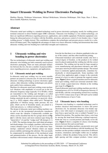
would start by using a device equipped with an ultrasonic detector to detect the presence of a vehicle ina parking space. We then decided that we wanted to implement a Wireless Sensor Network (WSN),forgoing using wired connections in order to reduce the material cost of the system as well as to test thecapabilities of a WSN within a parking deck structure. We also knew that in order to differentiate oursystem design from others already out there, that we would need to take a new approach tocommunication with patrons of the parking deck to better inform them about the locations of potentialavailable spots that would be of interest to the driver. To achieve this we would need to design andwrite our own program to not only interface with our WSN but that would also allow for the level ofclear and precise communication between the parking structure and the driver. With the main goals ofour system in place we divided the work into three parts: Hardware, Networking, and Software andbegan to create.The system that our group has developed is relatively simple yet coupled with our softwarecreates a whole new level of interactivity between drivers and the parking deck, effectively creating the“smart” parking experience. Our system has three steps to it: Detection, Transmission, and Suggestion.The first step is detection, where our sensor, using ultrasonics, measures the distance between theceiling, where it is attached to, and the floor. This data is fed to our microcontroller, which takes theoutput signal of the ultrasonic detector and translates it into actual distance measurements. It thentakes this measurement and compares them to the known distance from ceiling to floor to determine ifa vehicle is occupying the spot. If the distance has decreased the sensor then waits and checks thedistance measurement again to see if the spot is still taken or if instead an object, such as a person,simply was walking under it. These sensors would be grouped together in clusters with sensorstransmitting their ID and spot state to clusterheads. These clusterheads would aggregate data andtransmit it to a main “hub” which would collect the data and use it to suggest the nearest available spotto drivers coming in. Suggestion is a key word here. When our group polled with the following question:
“For my senior design project, my group and I are planning on creating a system for privateparking decks that allows for the detection of whether a parking spot is available or full. Thiswould allow drivers to be more informed as to where there are open spots and whether or notthe parking deck is even full or not thus making parking more swift, less stressful, and moreefficient overall.If you were paying to park in a garage outfitted with the system described above, would you bewilling to be told where to park according to parking spot availability regardless of location?”Of the 149 people who responded 80% said yes while 20% said no. In order to account for the 20% wedecided to allow our system to put parking spots that were detected into a temporary array where aftera few minutes the state of the suggested spot would be checked to see if the spot was indeed taken ornot. If the spot was then it is deleted from the temporary array, however if the spot was not taken, thenthe spot is simply returned to the array of spots currently open. Implementing this has allowed oursystem to be much more lenient while simultaneously maintaining the precise spot locating we set as arequirement for our system.Fig. 3. Block diagrams for the programming of the space sensor (left) and the suggestion program (right)
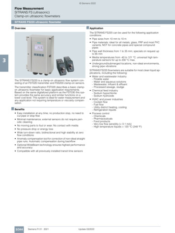
4. HardwareCreating the sensor itself for our system was, as it was with every part of this project, aniterative process. When first brainstorming the ideas that would lead to our system, we knew amicrocontroller would be a necessity. It would give our sensor the processing power needed to controlthe ultrasonic detectors as well as power the XBee wireless modules. Being that this was going to be awireless sensor we also wanted a microcontroller that was optimized for said tasks and would be able tohandle them in an efficient manner. After more research, however, a compatibility issue was found andour focus had to shift to another more compatible version. The microcontroller we ended up with wasthe Arduino Uno.Fig. 4. Image of Arduino Uno microcontrollerSmall enough in size yet still able to handle the calculations and logic we needed with ease, the Unoproved to be a simple and reliable piece of hardware to code for. The tradeoff came in the form of largersize than the first considered and wireless optimized Arduino Fio as well as larger power consumption at
234mW as the Uno was designed more for being plugged into a wall than into a battery. Moreinformation on battery life can be found in the testing section of this report.Along with our chose of microcontroller, a choice of which ultrasonic detect to use needed to bemade. Many of the ultrasonic detectors came in the form of having five connectors (5V, TRIG, SIG, GND,and a connector that was not usually supposed to be connected) and reliability as well as energy useoften were issues. The decision was made to go with the Parallax PING))) sensor. This ultrasonic detectorused a more “user-friendly” three-prong connector layout (5V, SIG, GND) and had power consumptionthat made it stand out from the rest at 100mW.Fig. 5. Parallax PING))) ultrasonic detector (left) and a basic circuit schematic for interfacing with ArduinoControlling the PING sensor was done using the Uno microcontroller, which would trigger the sensor viaa “LOW, HIGH, LOW” pulse to the SIG connector. The sensor would then send out three short pulses ofsound at a frequency of 40kHz and time how long the echo took to return in microseconds. The soundemitted has a spread of 15o from center. If the average parking deck is approximately 114 inches thisworks to a circular detection area of diameter 61.1”. The microcontroller then receives that data fromthe SIG connector and changes that time into a distance. It does this by dividing the time first by 74because on average it takes sound waves 74 microseconds to travel an inch. This gives the total traveldistance from the PING sensor to the object and back so it is necessary to divide this value in half to get
the distance to the object. The Uno then makes a quick logic comparison between the newly founddistance and the known distance from floor to ceiling to determine if the spot is taken and changes itstate as outlined earlier.From the beginning we knew we would need to build a wireless sensor network (WSN) in orderto connect all these sensors. The Xbee modules were an obvious choice for our group considering theywere built around the Zigbee standard and thus has its own protocol already in place. To go along withthis was an Xbee shield designed to create the circuitry necessary for the Arduino and XBee tocommunicate. The Xbee itself was designed to draw 35mA while transmitting at 3.3V. More informationon the Xbees and the Zigbee standard can be found in our networking section of this report.Fig. 6. Xbee Series 2.5 module (right) and Xbee shield (left)When all of these pieces were brought together our sensor was created. All that was neededwas a power source and our “hub”. With a sensor ping cost of 115.5mW 100mW 234mW 449.5mW.The Duracell 9V battery provides on average around 500mWh and for the purposes of making a proof of
concept worked out perfectly fine. We were even able to use the regular wall adapter plug built into theUno so that we could use the built in voltage regulator circuit.Fig. 7. A completed ceiling sensor for our networkOur “hub” needed to be nothing more than another Xbee, which acted as our receiver connected to acomputer, which aggregated all the data being sent from the sensors.Fig. 8. The receiver for our “hub”
5. NetworkingIn terms of networking, the “Smart Park” system implements a unique and highly efficientnetworking scheme in order to avoid the seemingly obvious troubles within a concrete parking garagestructure. In fact, the first major hurdle with the design concept was the issue of transmitter to receivercommunication (router to central HUB). In order to bypass the need for long range communication andavoid the various complications of environmental blockades, we examined the United States Military’scurrent use of “Wireless Mesh Networks”.A Wireless Mesh Network is a network composed of various radio nodes which have the abilityto communicate from one node to another in a rather quick and simple fashion. The information will‘bounce’ from router to router until the data is finally received by the primary coordinator which thendelivers the data to the user. In theory, a full implemented multi story parking garage system wouldinclude approximately one or two coordinators on each garage floor. The coordinator would then gatherall the data from the parking space routers and would relay the total data to the floor below. Thistopology will continue to snake its way down until it reaches the central processing HUB in the lobby.For demonstrative purposes our final hardware setup is composed of five routers which send theparking status data directly to a main coordinator. Smart Park’s final topology is called a “Star” typetopology because the coordinator radio sits at the center of the network while being circled bysurrounding router node.Fig. 9. Visualization of Network Design
The FCC certified mode of enabling such a network is called IEEE 802.15.4, which is also knownas “ZigBee”. IEEE 802.15.4 radios operate in unlicensed bands including 2.4 GHz, 900 MHz and 868 MHz.The most compatible and documented modern hardware utilizing this ZigBee standard is Digi’s line of‘Xbee’ communication modules. Operating at 2.4 GHz operating frequency with an output of 2mW, theXbees have to ability to communicate within a range of about 120 meters. Communications betweenXbee modules vary in two primary command sets, and programming of the modules allows for 128-bitencryption. For our system “Xbee ZNet 2.5 Antenna (XB24-B)” modules are used. Each device includes asmall omnidirectional antenna which allows for physical space minimization and the ability to avoidpotentially bulky antennas. Omnidirectional meaning that when the wire is fixed upwardsperpendicularly the max transmission distance will be the same in all directions.Fig. 10. Image of XBee Series 2.5 moduleIn order to fine tune the module for the system’s particular needs, a program called “X-CTU” isused to manually program individual features of the Xbee’s firmware. Programming involves the use of asingle USB board which includes the proper pins for easy hardware reading; this USB board avoidsbreakout boards and messing wiring techniques for managing the device’s firmware. Xbee firmwareincludes seven primary categories of options including: Networking, RF interlacing, Serial interlacing,sleep modes, IO settings, diagnostic commands, and AT command settings. In this particular system themost important elements of the Xbee’s firmware is the PAN address (a universal address for every
device in the entire network which creates an appropriate channel for node communication), the 16bit/64-bit destination address (how the parking spot detector devices will know to specificallycommunicate with its required end device), and baud rate (the rate of pulses per second sent orreceived by the module). Each Xbee is read and modified by properly setting the COM port assigned tothe module by a PC and by choosing the appropriate “baud rate” of the Xbee (which is almost always9600 pulses per second by default). For our design, Xbees used for reading parking spaces will be syncedwith Arduino microcontrollers, so this requires the baud rate for every Xbee (including the coordinator)to be set at 57600 pulses per second. When X-CTU software verifies that the module can be read, the “XB24-B - ZNET 2.5 Router/End Device AT” firmware can be uploaded to the device. This gives one theability to set the device to specifically send “AT commands” to the specified coordinator HUB Xbee. Thecoordinator will be programmed to explicitly receive AT commands from these surrounding Xbee routernodes. AT commands refer to an interactive setup descending from the classic Hayes command set. InAT mode the device can only transmit AT data packets to one other device, as each device will shareeach other’s destination addresses, enabling directed one to one communication.Fig. 11. Screencap of setting up COM port
In the “Smart Park” system, Xbees programmed as “Routers” serve to specifically create awireless COM channel which transmits spot availability data directly to its programmed “Coordinator”destination address. Each Xbee module is hardwired with a predetermined Address LOW and AddressHIGH, and these addresses can be discovered by either reading the firmware using X-CTU, or bymanually reading the printed address on the backside of the module. Because the coordinator in ourstar configured system is required to read from ALL router nodes in the network, it must beprogrammed in another command set called “API mode”. ‘API’ stands for application programminginterface and is a set of standard interfaces which allows the device to read from more than onemodule. The coordinator Xbee programmed in API mode (XB24-B - ZNET 2.5 Coordinator API) does notinclude destination addresses for it is designed to receive data from all devices with the same PAN ID inthe network. Each router node however MUST be required to be programmed with the coordinatorsaddress HIGH and LOW.Fig. 12. Screencap of configuration screen for coordinator(left) and router/end device (right)
So overall, Xbees connected to adruino microcontrollers via specialized hardware interfaceshields (Routers/End Devices) communicate in AT command sets sent directly to an API configuredcoordinator HUB, which is physically connected to a PC via USB. The API configured coordinator knowsto receive data from any router node which has its same programmed PAN ID and that data is then readfrom the appropriate COM port. For testing purposes a program called Tera-Term was used to verifyreceived data.Fig. 13. Screencap of setting up Tera-Term6. SoftwareSoftware DesignOur software has to be able to interpret the data stream incoming from the CommPort. Theincoming data may have some other information and errors that we need to process and ignore becausewe are only interested in the information about each spot in the parking lot. After the information isprocessed the useful data will be store in the backend which will contain all the information about theparking spots. This backend is updated continuously as soon as useful data is in the CommPort. Theprogram reads the data from the CommPort as long as it is ready. It has a listener waiting for data to be
ready and that triggers the software to read the datastream and update the array if necessary. For thematter of testing we have the basic command prompt design and two interfaces which use GUI.Programming LanguageJava Programming Language is the one selected to handle the information incoming from theCommPort and to display the results.Why Java Language?-Java Language is simple-It is object-orientated which gives us a lot of flexibility in how to implement and solve the problem.-It is also secure, the information can be private and protected from third parties.-Java is reliable. A lot of testing can be performed. Debugging is easy and this allows us to attack themain source of any problem.-Platform-Independent, this is one of the best advantages that java brings. We can basically “WriteOnce, Run Anywhere”.Fig. 14. Steps to convert source code into machine code
The source code in java can be written in any type of Operating System and be compiled inanother one besides the first one used. The ‘java source’ is converted into ‘byte code’ through thecompiler. Then this bytecode is translated into Machine code using the Java Virtual Machine (JVM). Thisis the key step because the JVM is independent from the Operating System where it is. Instead of usingthe CPU to obtain the Machine code the JVM generates the machine code for a specific Operatingsystem using as a source the same bytecode that would be generated in other Operating Systems.Software ArchitectureSince engineering and life changes daily we would like to look for an architecture that allows usto modify our software without doing too many changes in the user interface. This project hascommercial purposes, which means that any update in the software should not bother the customer byinstalling a new version. That is why the user interface most of the time should be the same and allupdates and changes should happen in the back.Model-View-Controller (MVC) ArchitectureThe MVC architecture is independent and allows our program to be flexible. Since all parts areindependent they can be updated easily and errors can be found in a fast way. We basically organize thesoftware in three parts and each one has its own objective and functionality.
Fig. 15. MVC architecture graphical representationModel: The representation and management of the system’s dataView: The user's interface to the systemControl: The algorithmic logic, decision-making and data manipulation processesFig. 16. Independency of the MVCThe MVC software architecture gives us extensibility, robustness and code irredundancy. Theview will only access the backend to read and write data. All other functions have to go through theControl Part which will be the bridge for almost everything between the View and Backend part.
In our case Fig#4 represents our final design. As we may notice the backend contains the Data,which implements the data structure where the spots are going to be store. The class Spot will containall the information about each spot, such as name, availability, location, etc. In the Control part we havethe ControlTodo class which will handle all the methods and connect the View and backend using theComControl class which reads the information from the CommPort. Theutil package is a common package that can be used by any component toread and display information in the console. The View Part contains allthe classes that conform the GUIViews and the test class is thesimpleView.Data Stream ProcessingFig. 17. Our MVC designWe first need to create a virtual ComPort from where to read the information coming from theXbees. After the port is initialized and open we are able to read any incoming information in bytes.As we agreed every sensor located above each parking spot will send the information about theavailability of its spot. The format chosen is “SIDXXX Y”, where ‘XXX’ represents the spot number and ifY 1 the spot is available otherwise if Y 0 the spot is currently taken. As the information reaches the portour program will read it and remove it from the buffer of the CommPort.Other Data Incoming (Garbage)Since there is noise and other factors in the environment that will affect the data streamincoming we have create methods to eliminate the extra information. Our program will grab each byte
of information and only when the exact sequence “SID XXX Y” is found it will update the specific spotstatus.Incomplete Data StreamWhen there is information in the CommPort ready to be read the programs grabs it and processes it.Often the data stream may cut the expected format “SIDXXX Y” in two pieces since there are a lot ofother bytes (garbage) also in the buffer. In order to avoid missing this format at this time our softwarewill be sensing the data stream and once it finds the letter “S” a counter will begin in order to hold thefirst part of the format. Then when the second data stream is ready in the buffer the program checks ifthe counter was initialized before and it appends at the beginning of the new data stream the last fewbytes from the first one. This way we will not lose the any possible right format incoming if it is shop atthe buffer. In order to update the spots status the format has to be exactly SIDXXX Y.Data Stream AnalyzerThe first approach implemented was to read byte per byte from the buffer and pass each one tothe method that is looking for the right incoming format. This approach failed since when we have morethan one sensor the amount of information increases and the programs cannot catch up with the actualstatus of the spots.As a second and more effective approach we have read all the information from the port andstore it into an array of bytes. So now we have access to more bytes in a faster way and we processes itquickly since the array allows us to access to each byte at O(1 ) times in terms of Big O.Multi-Threads
Our software is basically two programs in one that share the same information about the spots,stored either in an array or another type of data structure.Both threads are totally independent except when one of them stops which causes the otherone to stop as well. One thread will be constantly listening the CommPort waiting for information toarrive. When the information is ready it triggers this thread to process the incoming data stream. Then ifit is the case, the data structure holding the spots information is updated. It may be updated with thesame status that it was before. It would be a waste of time to just update the information in those thatchange the status because that will introduce an-if statement. It is faster just to replace the status of thespot with the incoming value without looking at the previous value. The user never interacts with thisthread. It runs in the back and it stops when the second thread stops, which is the user interface.The second thread will contain the friendly information about the spots that the user will see.When the user enters the garage the second thread generates a GUI interface in a screen which tells theuser the nearest or all the spots available in the building. Different set ups and version of the GUIViewcan be used without changing the Control and Model part. This is the great advantage that the MVCarchitecture offers to us.Model, View and ControlSimpleViewFig. 18. SimpleView, command prompt
We first implemented a command prompt view, Fig. 18, where we created randomly the data structurecontaining the spots statuses. The spots were generated randomly and the options were limited. Yet,this helped us to start building the MVC architecture.GUIViewsSince we are using the MVC architecture it is easy for us to replace the previous simpleView with anyother View. For this project we created a more sophisticated GUIView which will be able to display thestatus of all the spots available, the ones taken, the nearest spot and a small description of the locationof them.Fig. 19. GUIView with all the options.As a second approached since we had 5 sensors we created a specific view for those five which turnedred if the spot was taken otherwise green. This was the first time we had tested the program with morethan 2 sensors and it worked well. The reaction was almost instantaneous and the program had no
problem at all when reading a higher amount of data from the port.Fig. 20. GUIView of 5 spotsEach GUIView replaced and the SimpleView and they were reading the status of the spots from thebackend. Then the next step was to update the backend with the real information. So far the Controlpart was generating the spots randomly which updated the backend with these random values.CommPort Reading, ControlReading from the CommPort was the key part of the programming part of the project. Java doesnot have a built in library for this. An external library was added ‘comm.jar’ which allowed us to openthe port and read the data stream. This is the main stone of the Control part which will interact with thebackend updating each spot’s status.The View part accesses the data structure and gets the spot status while this data is beingupdated by the Control part using the information at the CommPort.7. TestingTesting of the hardware of the system was an ongoing process. It began with simply testing tosee if the original Arduino units found were in working order or not. This led to testing of a simplyrangefinder which was simply an Arduino with a PING sensor int
main issue with many of the options for creating a more convenient solution for parking management is the upfront installation cost. As stated before the price per parking spot of a conventional parking deck is around 15,000. To create a compelling system, one must minimize the increase to this ratio of cost per spot.