Transcription
CAUTIONWARNING – EXPLOSION HAZARD – SUBSTITUTION OF COMPONENTS MAY IMPAIRSUITABILITY FOR CLASS I, DIVISION 1, OR EQUIVALENT AS STATED IN USER MANUALAVERTISSEMENT – RISQUE D’EXPLOSION-LA SUBSTITUTION DE COMPOSANTS PEUTRENDURE CE MATERIEL INACCEPTABLE POUR LES EMPLACEMENTS DE CLASSE I,DIVISIONCAUTION: FOR SAFETY REASONS, THIS EQUIPMENT MUST BE OPERATED ANDSERVICED BY QUALIFIED PERSONNEL ONLY. READ AND UNDERSTAND THEINSTRUCTION MANUAL COMPLETELY BEFORE OPERATING OR SERVICING.ATTENTION: POUR DES RAISONS DE SECURITE, CET ÉQUIPEMENT DOIT ETREUTILISE ENTRETENU ET REPARER UNIQUEMENT PAR UN PERSONNEL QUALIFIE.ETUDIER LE MANUEL D' INSTRUCTIONS EN ENTIER AVANT D' UTILISER, D'ENTERETENIR OU DE RÉPARER L' ÉQUIPEMENT.CAUTION: THIS AREA MUST BE FREE OF FLAMMABLE GASES DURING CALIBRATION.ATTENTION : CETTE ZONE DOlT ETRE EXEMPTE DE GAZ INFLAMMABLES PENDANTL'ETALONNAGE.CAUTION:TO PREVENT IGNITION OF EXPLOSIVE ATMOSPHERES, REMOVE FROMEXPLOSIVE ATMOSPHERE BEFORE SERVICINGDANGERDANGER: OTIS INSTRUMENTS INC. OI-6900-LEL IS AN AMBIENT AIR COMBUSTIBLEGAS SENSOR ASSEMBLY AND ONLY MONITORS IN THE IMMEDIATE VICINITY OF THESENSOR HOUSING. A SITE SURVEY IS REQUIRED IN ORDER TO DETERMINE THE BESTPLACEMENT AND QUANTITY OF SENSOR ASSEMBLIES. IMPROPER INSTALLATIONCAN LEAD TO AN UNDETECTABLE GAS LEAK WHICH COULD RESULT IN PERSONALINJURY OR LOSS OF LIFE.
TABLE OF CONTENTSTABLE OF CONTENTS11.11.21.31.3.11.3.21.3.3PRODUCT OVERVIEWINTRODUCTION . 1PRODUCT SPECIFICATIONS . 2SYSTEM DIAGRAMS . 3EXTERNAL SYSTEM DIAGRAM . 3INTERNAL SYSTEM DIAGRAM. 4ASSEMBLY DIAGRAM . 522.12.22.32.3.12.3.22.3.32.42.5INSTALLATION AND START-UPPRODUCT PLACEMENT . 6PRODUCT MOUNTING . 7WIRING CONFIGURATIONS . 8OPENING THE ENCLOSURE . 9CONNECTING THE BATTERIES. 9CLOSING THE ENCLOSURE . 10SYSTEM START-UP . 10NORMAL OPERATING MODE. 1133.13.1.13.23.33.43.53.63.73.8PRODUCT SETTINGS AND CONFIGURATIONRELAY TEST . 13PERFORMING THE RELAY TEST . 14NETWORK ID . 14SYSTEM INFORMATION . 15NULL/CALIBRATION TIMER INFORMATION . 15UNIT INFORMATION . 16BACKGROUND SETTING. 16DISPLAY SCREEN CONTRAST SETTING . 17RETURN TO FACTORY DEFAULT SETTINGS . 1844.14.1.14.1.24.24.2.14.2.24.3OPERATION SETTINGSPOWERING THE DEVICE . 20POWERING ON . 20POWERING OFF. 20SENSOR CALIBRATION . 21NULLING THE SENSOR . 21CALIBRATING THE SENSOR. 23SENSOR RADIO ADDRESS . 2555.15.25.35.45.5PRODUCT MAINTENANCESCHEDULED MAINTENANCE. 26SENSOR REPLACEMENT . 27BATTERY REPLACEMENT . 28PRODUCT TROUBLESHOOTING . 30PRODUCT REPLACEMENT PARTS AND ACCESSORIES . 32OI-6900-LEL OPS GUIDE REV 3.0i
TABLE OF CONTENTSAPPENDICESAPPENDIX A: PRODUCT WARRANTY STATEMENT . 34APPENDIX B: INFORMATION ABOUT RMA SERVICE REPAIRS . 37APPENDIX C: INFORMATION ABOUT RMA RETURNS FOR CREDIT . 39iiOI-6900-LEL-X-O-2B OPS GUIDE REV 3.0
PRODUCT OVERVIEW1 PRODUCT OVERVIEW1.1 INTRODUCTIONThe Otis Instruments, Inc. (Otis) GEN II Model OI-6900-LEL-X-O-2B (OI-6900-LEL) Explosion-Proof Ambient AirCombustible Gas Detector is designed to detect a wide range of hydrocarbon gases in potentially hazardousenvironments. This product’s enclosure is CSA certified as Class I, Division 1, Groups C and D. The OI-6900-LELfeatures non-intrusive magnetic switches that allow for complete system configuration, regular calibration, andproduct maintenance to be performed in the field, without opening the enclosure and breaking the seal, therebycompromising the explosion-proof rating. Non-intrusive interface with the OI-6900-LEL is made possible by use ofthe Otis Magnetic Tool included in the purchase of the device.The OI-6900-LEL continuously monitors the gas level of the surrounding environment and reports once every minute,the reporting rate will increase to once every five seconds when the detected gas is above the Background Gas setpoint. This set-point is adjustable to account for sites that may have a constant low level of gas always presentallowing the OI-6900-LEL to maintain a long battery life. When the gas level drops below the set-point the reportingrate will return to once every minute. The OI-6900-LEL display screen will always show the present concentration ofgas being detected by the sensor assembly. More information about the Background Gas Set-point is found later inthis manual.This document is an operation manual containing diagrams and step-by-step instructions for the proper and safeinstallation, start-up, configuration and settings, normal operation, and product maintenance of the OI-6900-LEL.In this manual, the instructions reference the use of push-buttons, located on the front panel of the device. Inpotentially hazardous environments, the activation of the non-intrusive magnetic switches, through the use of theOtis Magnetic Tool, will replace the directive of the button-press actions. To apply the Otis Magnetic Tool, hold thetool to the side of the device enclosure adjacent to the push-button that you wish to activate. When the magneticswitch is toggled, an on-screen indicator will appear on the display screen, signifying that a connection was made.NOTICEThis document should be read in its entirety before the initial operation of the product.Should a question arise during the use of the product, this document will serve as a first reference for the end-user.For inquiries beyond the information and instructions provided within this manual, contact the sales representativeof this product for assistance.OI-6900-LEL-X-O-2B OPS GUIDE REV 3.01
PRODUCT OVERVIEW1.2 PRODUCT SPECIFICATIONSSystem SpecificationsOperating VoltageBattery LifeOperating Temperature RangeHumidity RangeMeasurement RangeResponse TimeWireFree Radio OptionRF ConnectionDisplayInterfaceMechanical SpecificationsEnclosure MaterialsSensor Housing MaterialsProduct DimensionsProduct Weight2 batteries, 3.6 VDC 19Ah each, 38 Ah total, Lithium-Thionyl (Li-SOCl2)Expected Battery Life of Up to 1 year-40⁰C to 54⁰C0% to 98% Relative Humidity, Noncondensing0% to 100% LELT90 50 secondsGEN II 900 MHz – 52 Networks, 255 Sensors per NetworkGEN II 2.4 GHz – 78 Networks, 255 Sensors per NetworkN-Female Radio Frequency (RF) ConnectorTransflective (sunlight-readable)102x64 LCD ScreenLED Back-Light3 Push-Buttons (MENU, ADD, SUB)3 Magnetic Switches for Non-Intrusive CalibrationAluminum Device Enclosure303 Stainless Steel Sensor Housing5.42 " L x 6.03" W x 17.03" H (Maximum w/ Attachments)5.75 lbs. (Maximum w/ Attachments)Safety ApprovalsMain EnclosureExplosion/Flame-ProofMain EnclosureClass I, Division 1, Groups C & DHazardous Location CertificationExd IIBZone 1, Aex d IIBTamb -40⁰C to 60⁰CSensor EnclosureExplosion/Flame-ProofSensor EnclosureClass I, Division 1, Groups C & DHazardous Location CertificationTamb -40⁰C to 60⁰C2OI-6900-LEL-X-O-2B OPS GUIDE REV 3.0
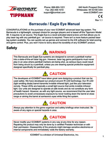
PRODUCT OVERVIEW1.3 SYSTEM DIAGRAMSRefer to the following diagrams for identification of the external and internal system components that may be referredto in this manual.1.3.1EXTERNAL SYSTEM DIAGRAM12345678910111213141516MENU ButtonFront Panel ThumbscrewEnclosureAntenna FittingAntennaMounting HoleSUB ButtonSensor HousingRain GuardADD ButtonEnclosure GroundSet ScrewLCD Display ScreenEnclosure LidOtis Magnetic ToolCalibration Cup Kit(Sold Separately)⑭⑯OI-6900-LEL-X-O-2B OPS GUIDE REV 3.0⑮3
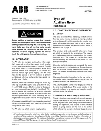
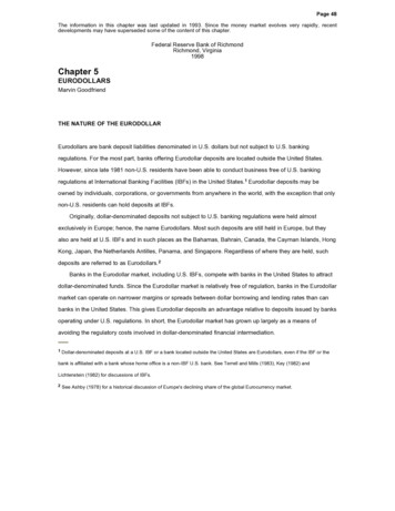
PRODUCT OVERVIEW1.3.2INTERNAL SYSTEM DIAGRAM⑦12345674Sensor Housing ConnectorSensor Housing PlugBatteriesRadio ModuleBattery ConnectorsAntenna Fitting ConnectorBattery Spring ClipsOI-6900-LEL-X-O-2B OPS GUIDE REV 3.0
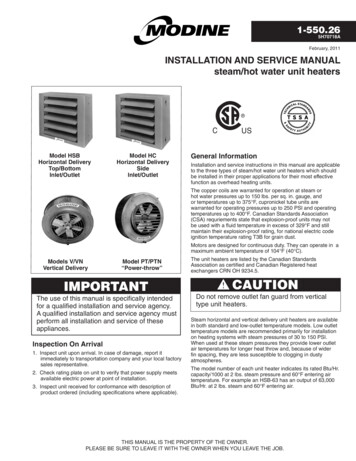
PRODUCT OVERVIEW1.3.3ASSEMBLY DIAGRAM12345678910111213OI-6900-LEL-X-O-2B OPS GUIDE REV 3.0Enclosure LidInternal SystemAntenna Fitting ConnectorEnclosureAntenna Fitting900 MHz AntennaOR2.4 GHz AntennaSensor Housing BaseSensor Adapter BoardSensor ElementSensor Housing CapWith Flame ArrestorSensor Rain GuardSensor Housing Plug5
INSTALLATION AND STARTUP2 INSTALLATION AND START-UP2.1 PRODUCT PLACEMENTThe installation instructions, and any other information supplied by Otis, provide only basic guidelines relating to theproperties of combustible gas and the effects of environmental conditions on the OI-6900-LEL device. Sensorplacement should be determined in consultation with the site safety personnel, as well as those knowledgeable of:(1) the site/facility where the equipment is being installed and (2) the potentially present gas types and theirdispersion. Otis strongly recommends that the end-user consults with the appropriate third party Health, Safety andEnvironmental (HSE) and Industrial Hygiene (IH) professionals to determine the final quantity and placement of yourgas detection devices.The primary purpose of the OI-6900-LEL is to provide an early warning of the accumulation of flammable gas, inorder to minimize hazards to people and property. Proper placement of the device is paramount to achieving thisgoal.The following general guidelines should be considered when determining the placement of the OI-6900-LEL: The unit shall be placed such that the position of the rain guard is pointing downward to the ground. Avoid installing the unit in a location where airborne particles could cover or coat the sensor head. The unit should be placed in an area that will produce the highest gas concentration. Enclosed corners andstopping points of moving devices are two areas susceptible to a buil
The Otis Instruments, Inc. (Otis) GEN II Model OI-6900-LEL-X-O-2B (OI-6900-LEL) Explosion-Proof Ambient Air Combustible Gas Detector is designed to detect a wide range of hydrocarbon gases in potentially hazardous environments. This product’s enclosure is CSA certified as Class I, Division 1, Groups C and D. The OI-6900-LEL