Transcription
34th Annual Precise Time and Time Interval (PTTI) MeetingTIMEKEEPING AND TIME DISSEMINATION IN ADISTRIBUTED SPACE-BASED CLOCK ENSEMBLES. FrancisZeta Associates IncorporatedB. Ramsey and S. SteinTiming Solutions CorporationJ. Leitner, M. Moreau, and R. BurnsNASA Goddard Space Flight CenterR. A. NelsonSatellite Engineering Research CorporationT. R. BartholomewNorthrop Grumman TASCA. GiffordNational Institute of Standards and TechnologyAbstractThis paper examines the timekeeping environments of several orbital and aircraft flightscenarios for application to the next generation architecture of positioning, navigation, timing,and communications. The model for timekeeping and time dissemination is illustrated byclocks onboard the International Space Station, a Molniya satellite, and a geostationarysatellite. A mathematical simulator has been formulated to model aircraft flight test andsatellite scenarios. In addition, a time transfer simulator integrated into the Formation FlyingTestbed at the NASA Goddard Space Flight Center is being developed. Real-time hardwareperformance parameters, environmental factors, orbital perturbations, and the effects of specialand general relativity are modeled in this simulator for the testing and evaluation oftimekeeping and time dissemination algorithms.1. INTRODUCTIONTimekeeping and time dissemination among laboratories is routinely achieved at a level of a fewnanoseconds at the present time and may be achievable with a precision of a few picoseconds within thenext decade. The techniques for the comparison of clocks in laboratory environments have been wellestablished. However, the extension of these techniques to mobile platforms and clocks in space willrequire more complex considerations.A central theme of this paper – and one that we think should receive the attention of the PTTIcommunity – is the fact that normal, everyday platform dynamics can have a measurable effect on clocksthat fly or ride on those platforms. It is generally appreciated that clocks moving on satellites with a highspeed and at a high altitude are subject to relativistic effects. The principal example is the Global201
Form ApprovedOMB No. 0704-0188Report Documentation PagePublic reporting burden for the collection of information is estimated to average 1 hour per response, including the time for reviewing instructions, searching existing data sources, gathering andmaintaining the data needed, and completing and reviewing the collection of information. Send comments regarding this burden estimate or any other aspect of this collection of information,including suggestions for reducing this burden, to Washington Headquarters Services, Directorate for Information Operations and Reports, 1215 Jefferson Davis Highway, Suite 1204, ArlingtonVA 22202-4302. Respondents should be aware that notwithstanding any other provision of law, no person shall be subject to a penalty for failing to comply with a collection of information if itdoes not display a currently valid OMB control number.1. REPORT DATE3. DATES COVERED2. REPORT TYPEDEC 200200-00-2002 to 00-00-20024. TITLE AND SUBTITLE5a. CONTRACT NUMBERTimekeeping and Time Dissemination in a Distributed Space-BasedClock Ensemble5b. GRANT NUMBER5c. PROGRAM ELEMENT NUMBER6. AUTHOR(S)5d. PROJECT NUMBER5e. TASK NUMBER5f. WORK UNIT NUMBER7. PERFORMING ORGANIZATION NAME(S) AND ADDRESS(ES)8. PERFORMING ORGANIZATIONREPORT NUMBERZeta Associates Incorporated,10302 Eaton Place, Suite 500,Fairfax,VA,220309. SPONSORING/MONITORING AGENCY NAME(S) AND ADDRESS(ES)10. SPONSOR/MONITOR’S ACRONYM(S)11. SPONSOR/MONITOR’S REPORTNUMBER(S)12. DISTRIBUTION/AVAILABILITY STATEMENTApproved for public release; distribution unlimited13. SUPPLEMENTARY NOTESSee also ADM001507. 34th Annual Precise Time and Time Interval (PTTI) Planning Meeting, 3-5December 2002, Reston, VA14. ABSTRACTThis paper examines the timekeeping environments of several orbital and aircraft flight scenarios forapplication to the next generation architecture of positioning, navigation, timing, and communications. Themodel for timekeeping and time dissemination is illustrated by clocks onboard the International SpaceStation, a Molniya satellite, and a geostationary satellite. A mathematical simulator has been formulated tomodel aircraft flight test and satellite scenarios. In addition, a time transfer simulator integrated into theFormation Flying Testbed at the NASA Goddard Space Flight Center is being developed. Real-timehardware performance parameters, environmental factors, orbital perturbations, and the effects of specialand general relativity are modeled in this simulator for the testing and evaluation of timekeeping and timedissemination algorithms.15. SUBJECT TERMS16. SECURITY CLASSIFICATION OF:a. REPORTb. ABSTRACTc. THIS PAGEunclassifiedunclassifiedunclassified17. LIMITATION OFABSTRACT18. NUMBEROF PAGESSame asReport (SAR)1419a. NAME OFRESPONSIBLE PERSONStandard Form 298 (Rev. 8-98)Prescribed by ANSI Std Z39-18
34th Annual Precise Time and Time Interval (PTTI) MeetingPositioning System (GPS), where there is a net secular effect of 38 µs per day, a periodic effect with anamplitude of up to 46 ns, and a Sagnac effect of typically 100 ns for a stationary receiver on the geoid.What is not so commonly known is that motion associated with, for example, aircraft can also result inmeasurable relativistic effects. We have measured such effects on recent flight tests and have modeledthem via simulation. It is a surprise to many people that airborne platforms move fast enough, fly highenough, or cover enough distance to cause large enough effects to care about. In fact, atomic clocks canpotentially exhibit relativistic effects even by their transport in a moving ground vehicle. For example, ata velocity of 65 km/h over a distance of 100 km, the time dilation correction is 10 ps.This fact is one of the motivating factors for developing Two-Way Time Transfer (TWTT) technologyadapted to moving platforms. Hence, it underlies much of our research program. This paper will coverbackground on clocks, timescales, and time dissemination, and will discuss some of the theoretical andexperimental studies that we are doing in this area. In addition, we will provide a representative set ofinteresting simulation results specific to ground/space time-transfer.2. TIME MEASUREMENTThe measurement and dissemination of time involves three distinct aspects: (1) the creation of a networkof clocks, (2) the formation of a timescale, and (3) the development of algorithms for time transfer withina conventional spacetime coordinate system.2.1 CLOCKSA clock consists of a device capable of counting the periods of a repeatable phenomenon, whose motionor change of state is observable and obeys a definite law. Cesium or rubidium clocks of the type carriedonboard GPS satellites have a precision on the order of a few parts in 1014, or about 10 ns over a fewhours. Hydrogen maser clocks in the laboratory offer a precision of a few parts in 1015 or 1016.Technologies under development, such as those involving cesium fountain clocks, will improve theseprecisions.The definition of the second describes a perfect clock, which is one that runs at the hyperfine frequency ofthe ground state of the cesium-133 atom at rest at a thermodynamic temperature of 0 K. This definitionimplies an isolated atom with no perturbations, which would make the clock unobservable. On the otherhand, a real-world cesium clock permits the observation of the near ground-state hyperfine transition inmany cesium atoms. Precision clocks have two types of imperfections: variations in period due to noiseand those due to environmental influences.There are two types of noise associated with the observation process – variations in the number of atomsthat make a hyperfine transition due to the quantum nature of the transition process, and counting or shotnoise of the detector. Both noise sources cause the phase of the clock to execute a random walk. Thetime of the clock diverges, but the frequency of the clock does not change. This type of noise is calledwhite frequency noise. The clock signal is delivered to users through a system of synthesizers and outputamplifiers that dominate the noise outside the bandwidth of the clock’s control loop. Thermal noise inthis signal processing circuitry causes the phase to change without diverging. This type of noise is calledwhite phase noise and dominates the high frequency part of the clock’s spectrum. The clock’s noiseperturbations are unavoidable, since they originate in the laws of quantum mechanics andthermodynamics.202
34th Annual Precise Time and Time Interval (PTTI) MeetingIn addition, there are environmental perturbations. These perturbations come from many sources. Forexample, the electromagnetic fields used to interrogate or confine the atoms and atom-atom collisions dueto confinement both shift the energy levels away from their ground-state values. The sizes of the shiftsare dependent on the operating conditions of the clock, such as temperature and pressure. As a result,environmental changes result in frequency changes of the clock. In principle, environmentalperturbations can be made arbitrarily small and, thus, can be avoided.2.2 TIMESCALESHistorically, timescales have been based on the rotation of the Earth on its axis (Universal Time), therevolution of the Earth around the Sun (Ephemeris Time), and the quantum mechanics of the atom(Atomic Time).Atomic Time has been maintained continuously in various laboratories since 1955. Coordination of theatomic timescales was entrusted to the Bureau International de l’Heure (BIH) in 1961 at the ParisObservatory (OP). The 14th General Conference on Weights and Measures (CGPM) in 1971 approvedthe establishment of International Atomic Time (TAI) as the coordinate timescale whose unit interval isthe second of the International System of Units (SI) as realized on the rotating geoid. In 1988,responsibility for TAI was transferred from the BIH to the International Bureau of Weights and Measures(BIPM). Approximately 250 cesium-beam standards and hydrogen masers located at observatories andnational metrology laboratories around the globe contribute to the formation of TAI.Coordinated Universal Time (UTC) is an atomic timescale that agrees in rate with TAI, but differs by anintegral number of seconds. Presently, UTC is behind TAI by 32 seconds. UTC is maintained within 0.9s of Universal Time (UT1), the astronomical timescale based on the rotation of the Earth, through theoccasional addition of a leap second step. The decision to insert a leap second is made by theInternational Earth Rotation Service (IERS). Initially, UTC was kept close to UT1 by both frequencyoffsets and fractional step adjustments in order to aid celestial navigation by matching the broadcastatomic time signal with the Earth’s rotation. The present UTC system of integral leap second stepswithout frequency offsets was adopted in 1972 so that an approximation to the epoch of UT1 and theinterval of the SI second would be provided in the same emission [1].2.3 RELATIVISTIC ALGORITHMSIn parallel to the development of clocks and timescales, there must be a corresponding theoreticaldevelopment of methods of time dissemination within an adopted spacetime coordinate system. Thesemethods involve considerations of hardware properties, propagation effects, and relativity physics.For relativistic time transfer, the distinction between coordinate time and proper time must be recognized.Coordinate time is a global coordinate that has the same value throughout all of space for a given event.In contrast, proper time is the time indicated by a clock in its own frame of reference and depends on thevelocity of the clock and the gravitational potential at the location of the clock.Relativity has become an important practical engineering consideration for modern precise timekeepingsystems. Thus, far from being simply a textbook problem or merely of theoretical scientific interest, theanalysis of both special and general relativistic effects on time measurement is an essential practicalconsideration. Neglect of these effects in satellite navigation systems would result in position errors onthe order of tens of meters. For measurements with a precision at the nanosecond level, there are threerelativistic effects that must be considered [2, 3].203
34th Annual Precise Time and Time Interval (PTTI) MeetingFirst, there is the effect of time dilation. The velocity of a moving clock causes it to appear to run slowrelative to a clock on the Earth. GPS satellites revolve around the Earth with an orbital period of 11.967hours and a velocity of 3.874 km/s. Thus on account of its velocity, a GPS satellite clock appears to runslow by 7 µs per day.Second, there is the effect of the gravitational redshift, a frequency shift caused by the difference ingravitational potential. (The term “redshift” is generic regardless of sign, but for a satellite clock thefrequency shift is actually a blueshift.) The difference in gravitational potential between the altitude ofthe orbit and the surface of the Earth causes the satellite clock to appear to run fast. At an altitude of20,184 km, the clock appears to run fast by 45 µs per day.The net effect of time dilation and gravitational redshift is that the satellite clock appears to run fast byapproximately 38 µs per day when compared to a similar clock at rest on the geoid, including the effectsof the velocity of rotation and the gravitational potential at the Earth’s surface. This is an enormous ratedifference for a clock with a precision of a few nanoseconds. To compensate for this large secular effect,the clock is given a fractional rate offset prior to launch of 4.465 10 10 from its nominal frequency ofexactly 10.23 MHz, so that on average it appears to run at the same rate as a clock on the ground. Theactual frequency of the satellite clock prior to launch is thus 10.229 999 995 43 MHz.Although the GPS orbits are nominally circular, there is always some residual eccentricity. Theeccentricity causes the orbit to be slightly elliptical. Thus, the velocity and gravitational potential varyslightly over one revolution and, although the principal secular effect is compensated by a rate offset,there remains a small residual variation that is proportional to the eccentricity. For example, with anorbital eccentricity of 0.02, there is a relativistic sinusoidal variation in the apparent clock time having anamplitude of 46 ns at the orbital period. This correction must be calculated and taken into account in theuser's receiver.The third relativistic effect is the Sagnac effect. The Sagnac correction in an Earth-Centered Earth-Fixed(ECEF) frame of reference is equivalent to a light-time correction for the receiver motion in anEarth-Centered Inertial (ECI) frame. For a stationary terrestrial receiver on the geoid, the Sagnaccorrection can be as large as 133 ns (corresponding to a GPS signal propagation time of 86 ms and avelocity of 465 m/s at the equator in the ECI frame). This correction is also applied in the receiver.The analysis of signals used in cross-link ranging, time transfer among satellites and ground stations, andinteroperability across constellations involves three steps: (1) a relativistic transformation from theproper time reading of the clock at the transmitter to the coordinate time of transmission in the adoptedcoordinate system; (2) calculation of the coordinate time of signal propagation, including both relativisticand nonrelativistic effects; (3) a relativistic transformation from the coordinate time of reception to theproper time reading of the clock at the receiver. In addition, all proper times must be corrected for“hardware” effects, such as signal noise and clock environment.For cross-link ranging, the secular corrections must be modeled, especially for satellite systems thatoperate at different orbital altitudes. In addition, the relativistic eccentricity correction must be applied byreceivers onboard the satellites themselves. Like those applied by ground receivers, these corrections willtypically be on the order of tens of nanoseconds.Analogous relativistic corrections will be needed in the European satellite navigation system, Galileo.Corrections beyond those already implemented in GPS will also be required if interoperability betweenthe two systems is to be achieved, especially if signals from the two systems are combined in the receiver.204
34th Annual Precise Time and Time Interval (PTTI) MeetingThe GPS has served as a laboratory for doing physics at the 1-to-10 nanosecond level. The consistentapplication of relativity to GPS time and position measurements has been demonstrated by the operationalprecision of the system and by numerous experiments designed to test these individual effects over a widerange of conditions. GPS thus represents a model for the application of similar corrections across a broadspectrum of timekeeping systems. Relativistic effects on satellite clocks and signal propagation for avariety of orbits are compared in Table 1 [2].Table 1. Relativistic Effects on Satellite Clocks and Signal Propagation.ConstantsVelocity of lightGravitational constant of EarthRadius of Earthm/s2997924583km /s2km6378.137J2 oblateness coefficient0.0010826Angular velocity of Earth rotationrad/sGeopotential on geoid U0m /sU0/c398600.442227.292E-056.264E 07-6.969E-10Satellite orbital propertiesSatelliteSemimajor 056.063.40.163.4InclinationdegArgument of perigeedeg000002500270Apogee igee nding node 320.1550.1460.1220.1460.07290.0729Period of revolutionMean 83.9533.8743.6453.8743.0753.075Secular time ular redshiftµs/d3.510.445.145.747.345.751.051.0Net secular effectAmplitude of periodic effect due toeccentricityPeak-to-peak periodic effect due r oblateness contribution to redshiftAmplitude of periodic effect due tooblatenessPeak-to-peak periodic effect due 7503833167027ps528573997665334054Amplitude of periodic tidal effect of Moonps0.00.01.01.21.81.26.16.1Amplitude of periodic tidal effect of Sunps0.00.00.50.50.80.52.72.7Mean velocityClock effectsSignal propagationMaximum Sagnac effectns1323131136155234218275Gravitational propagation delay along 6.75.9241.12.156.5Amplitude of periodic fractional Doppler shift10-12205
34th Annual Precise Time and Time Interval (PTTI) Meeting3. TIME DISSEMINATION VIA GPSThe GPS program evolved from earlier systems and was formally chartered in 1973. The system wasdeclared fully operational in 1995. The current GPS constellation consists of 28 Block II/IIA/IIRsatellites. Each Block II/IIA satellite carries two cesium and two rubidium atomic clocks, while eachBlock IIR satellite carries three rubidium clocks. The fundamental clock frequency is 10.23 MHz. Thesatellite clocks and monitor station clocks contribute to the statistical formation of a continuous systemtime known as GPS Time, which is specified to be within 1 µs of UTC, except leap seconds are notinserted. After corrections for ionospheric and tropospheric propagation delays, relativity, and hardwareeffects are taken into account, GPS can provide an absolute time reference with a nominal precision of 25 ns. However, in practice the precision can be 10 ns or better.The epoch of GPS Time is midnight of 5/6 January 1980. Therefore, GPS Time is behind TAI by aconstant value of 19 s. Presently, GPS Time is also ahead of UTC by 13 s. This difference changes everytime a leap second is inserted into UTC. GPS Time, TAI, and UTC are all realizations of the coordinatetime in either the ECEF or ECI frame of reference (which by convention is the same in both frames).GPS provides two types of global time service. The GPS satellites are considered to be a primary meansof time transfer among clocks operating in widely separated National Metrology Institutions and otherlaboratories via common-view techniques with an uncertainty of a few nanoseconds [4]. In addition, GPSbroadcasts a real-time prediction of UTC as maintained by the U.S. Naval Observatory (USNO).The precision and universal availability of time as disseminated by GPS has produced a paradigm shift,with GPS evolving from a secondary source of time to a major time reference in itself. For example, GPSis the primary source of UTC for the Greenwich Time Signal service of the British BroadcastingCorporation (BBC) [5].4. SATELLITE CLOCK SIMULATIONSTo study the theoretical importance of various hardware-related biases, environmental factors,propagation delays, orbital perturbations, and relativistic effects on satellite clocks, a Two-Way TimeTransfer Simulator has been developed as a MATLAB -based tool that simulates a series of measuredclock differences between moving platforms. Exchanges directly between two platforms or via a relayare supported. Noise contributions from a typical set of hardware components have been modeled,including special modules for clocks and modems. The platforms may have an arbitrary relative motion.The simulation conducts a series of signal exchanges between the two platforms. Each platform transmitsa timing signal according to a local clock’s on-time marker (OTM). The simulator performs thecalculations necessary to transform this local “hardware” proper time to an “ideal” proper time bycorrecting for the hardware biases. Then the coordinate time in an ECI reference frame is computed usinga relativistic transformation. Based on this coordinate time of transmission, the simulator searches for asolution to the time of fight between the platforms. At the receiving platform, the calculations areinverted to compute the ideal proper time and the hardware proper time of reception. Finally, theplatforms exchange their respective measurements of the difference between the local OTM and thereceived OTM, which are combined to determine the proper time difference between the clocks.The key features of the simulation are its inclusion of relativistic effects, hardware noise, and arbitraryplatform motion during the exchange. Relativistic effects are accounted for by the transformationbetween proper time and coordinate time in an ECI coordinate system. The simulator includes the time206
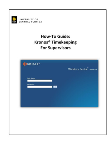
34th Annual Precise Time and Time Interval (PTTI) Meetingof-flight correction in the ECI reference frame, corresponding to the Sagnac effect in an ECEF referenceframe.Models for clock, modem, and measurement noise are implemented directly in the code. The simulatorsupports future modules to include variations in propagation delay. The clock noise is generated from athird-order model that includes noise densities for white phase noise, white frequency noise, frequencyaging, and random-walk frequency aging. Noise densities for a high-performance cesium standard areused in the simulations presented in this paper. Additionally, the algorithm itself can accept clocksteering inputs during the simulation. Modem noise is generated from a model that represents theperformance of a commercially available satellite modem with special modifications to transmit lowlatency OTM signals. Noise associated with the timer is based on the performance of a high-qualitytwo-channel timer. Platform motion may be specified in several ways: directly via a set of waypointsthat are time-stamped in hardware proper time, by a set of orbital elements, or generated algorithmicallyby a user-specified function.(a)(b)Figures 1(a) and 1(b). Error between actual clock offsets and measured offsets fortransfers between NIST and the ISS with (a) modem noise included and (b) modemnoise not included.Figures 1a and 1b show the simulation results for a fixed platform located at the National Institute forStandards and Technology (NIST) laboratories in Boulder, Colorado, USA and a moving platform in anorbit corresponding the International Space Station (ISS). Figure 1(a) includes the effects of modemnoise, while Figure 1(b) shows the results when the modem noise is not included. The simulation timecoincides with the portion of the orbit that is line-of-sight visible to NIST. Since the relative driftbetween the clocks themselves is removed from these plots, the resulting data show only the relativisticeffects associated with the platform kinematics and gravitational potential and the noise introduced by themeasurement and signal generation hardware. Analogous simulations were performed for an elliptical,highly inclined Molniya orbit and a geostationary orbit. Table 2 summarizes the range of errors for thesesimulations.207
34th Annual Precise Time and Time Interval (PTTI) MeetingTable 2. Error Ranges for Three Orbits.OrbitISSMolniyaGeostationary (GE-4 at 101 W)Error Range-55 to 53 ns-96 to 270 ns 2.8 to 3.3 ns5. FLIGHT TESTSGeotemporal Sciences (GTS) group personnel have conducted two series of flight tests to investigaterelativistic effects on clocks in subsonic airborne environments and to study and develop two-way timetransfer technology for these flight regimes.5.1 AT3 FLIGHT TESTSThree flights were staged from Edwards AFB in the timeframe of March and April 2001 in support of theDARPA-funded Advanced Tactical Targeting Technology (AT3) program. The focus of this programwas to develop and test a prototype system that will demonstrate that tactical (fighter and ground attack)aircraft can simultaneously accomplish their primary missions while satisfying SEAD/ESM requirementsif each is equipped with an ESM sensor and processor interconnected by a single, real-time network [6].A related requirement is that each participating aircraft must have sufficient knowledge of time and itsown position to support the ultimate target geolocation accuracy requirement of 50 meters CEP.The AT3 time recovery requirement was determined by Raytheon, the AT3 prime contractor, to be 8 nspeak relative time offset between participating aircraft. Because the time recovery mechanism waschosen to be passive via a GPS receiver (i.e., no GPS common view or active time transfer betweenplatforms), the absolute time recovery requirement was 4 ns peak error relative to a selected timescale,such as UTC or GPS Time. The GTS group was asked to provide metrology support for these flights byusing an atomic clock time reference onboard the T-39 test aircraft for comparison with the recoveredGPS Time. Our approach was simply to fly a high-performance cesium clock and measure the GPS Timeaccording to the GPS receiver relative to the atomic clock time throughout each flight using a timeinterval analyzer.The recorded time intervals were corrected for the relativistic effects on the clock due to the motion of theaircraft. The relativity corrections T (flying clock – reference clock) for gravitational potential(redshift), velocity (time dilation), and Sagnac effect were accumulated over time increments t by therelations T g gc2N ( h h ) tii 10i, Tv 12c2N vi 12i t i , Ts ωc2N Ri2cos 2 φ i λi ,i 1respectively, where c is the speed of light, g is the acceleration of gravity, ω is the angular velocity ofrotation of the Earth, h – h0 is the relative height above the geoid, v is the velocity, R is the distance fromthe center of the Earth, φ is the latitude, and λ is the longitude over the path taken.208
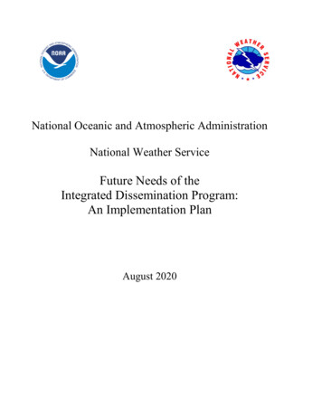
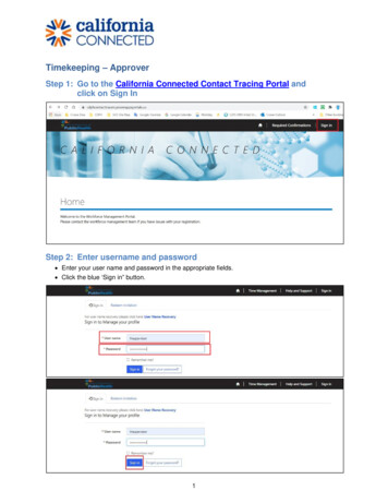
34th Annual Precise Time and Time Interval (PTTI) MeetingAircraft Speed Profile450400350300KTAS250200150100500Figure 2. Vertical flight profile.02000400060008000Time (sec)100001200014000Figure 3. Speed profile.The results of the first flight test are representative of many tactical military missions. The flight lasted3.62 hours, during which the aircraft flew a “right triangle” profile at latitude 36 (of approximatedimensions 4 5 in the sequence east, north, and southwest) at an altitude of about 8,200 m (27,000 ft),as shown in Figure 2, and at a typical speed of about 560 km/h (300 knots), as shown in Figure 3.Figure 4. Gravitational potential correction (redshift).Figure 5. Velocity correction (time dilation).From the recorded platform state vectors throughout the flight, the relativistic effects on the clock weredetermined analytically and were used to correct the time interval measurements between the GPS Timerecovered from a GPS receiver (equivalent to coordinate time in the ECEF and ECI reference frames),and the cesium clock proper time. Figure 4 illustrates the effect due to the difference in gravitationalpotentials between the flight clock and ground clock. This effect, which caused the flight clock to run fastby 9.40 ns relative to the ground clock, was the dominant relativistic effect. Figure 5 illustrates the effectdue to velocity, which caused the flight clock to run slow by 1.63 ns relative to the ground clock. Finally,Figure 6 illustrates the Sagnac effect, whose cumulative value of –0.10 ns is small because the flightcovered a closed path bounding a small area. The total relativistic effect on the flight clock is illustrated209
34th Annual Precise Time and Time Interval (PTTI) Meetingin Figure 7. As shown, when the flight was completed the flight clock was theoretically ahead of theclock on the ground by 7.67 ns. The actual flight clock data, when compared to the ground clock beforeand after the flight, was ahead by 7.3 1.7 ns. The uncertainty represents the one-sigma variation in thepre-flight clock com
model for timekeeping and time dissemination is illustrated by clocks onboard the International Space Station, a Molniya satellite, and a geostationary satellite. A mathematical simulator has been formulated to model aircraft flight test and satellite scenarios. In addition, a time transfer simulator integrated into the