Transcription
RAPID PROTOTYPING: A PARADIGM SHIFT IN INVESTMENTCASTING*Clinton L. AtwoodMichael C. MaguireMichael D. BaldwinBrian T. PardoFASTCAST Project TeamSandia National LaboratoriesPO Box 5800, Mail Stop 0958Albuquerque, NM, USA 87185-O958The quest for fabricating complex metal parts rapidly and with minimal cost has brought rapidprototyping (l2P) processes to the forefront of the investment casting industry. Relatively recentadvances in DTM Corporation's selective laser sintering (SLS) and 3D Systems stereolithography(SL) processes have had a significant impact on the overall quality of patterns produced using theserapid prototyping processes. Sandia National Laboratories uses patterns generat6 from rapidprototyping processes to reduce the cycle time and cost of fabricating prototype and small lotproduction parts in support of a program called FASTCAST. The SLS process is used to fabricatepatterns from materials such as investment casting wax, polycarbcmate, and a new material calledTrueFomi PMTF. With the timely introduction of each of these materials, the quality of patternsfabricated has improved. The development and implementation of SL QuickCastTh*software hasenabled this process to produce highly accurate patterns for use in investment casting. This paperwill focus on our successes with these new pattern materials and the infrastructure required to castrapid prototyping patterns successfully. In addition, a brief overview of other applications of rapidprototyping at Sandia will be discussed.BACKGROUNDSandia National Laboratories is a multi-program laboratory operated by the Lockheed MartinCorporation for the U.S. Department of Energy. As an engineering laboratory responsible for thedesign and manufacture of a vaxiety of electrical and electromechanical prototype devices, a needcontinually exists for production in a timely and more efficient manner. Over the years, Sandia'smanufacturing processes have evolved from labor-intensive, manually operated machine tools tocomputer-aided machining centers and wire-feed elecmcal discharge machines. Despite theseadvances in computer numerically controlled (CNC) machining, many components at Sandia stillrequired extensive and time-consuming fabrication and assembly.Sandia began producing investment cast prototypes in 1985. Cast primarily from aluminum orstainless steel, the prototype castings were produced months after the design had been finalizeddueto the time required to procure wax injection tools. Once the tool was available, further time wasused to determine proper methods of gating the part to produce a defect-free casting. often this* This work was supported by the Unitedunder contract DE-ACa4-94ALXWXI-
DISCLAIMERPortions of this document may be illegiblein electronic image products. Images areproduced from the best available originaldocument.\
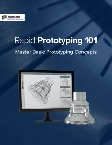
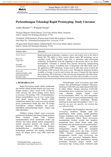
fRAPID PROTOTYPING A PARADIGM SHIFT IN INVESTMENT CASTING'2required several gating and rigging design iterations (see Overview of Investment CastingProcess). In an effort to speed the design and fabrication process of producing prototype castingsand eliminate the need to procure wax injection tools, several processes were used. The firstmethod used patterns that were fabricated by hand using sheet wax formed to closely resemble thecomponent. While crude in appearance and lacking the dimensional accuracy required,, these itemsusually served to evaluate mechanical behavior (vibration, shock and crush tests), but little else.The next method used CNC machining to produce patterns from blocks of wax. While moreaccurate, the time and cost associated with machining wax patterns was similar to'that ofmachining the metal part from wrought stock.The Rapid Prototyping Laboratory (RPL)at Sandia was established in 1990 with the acquisition ofa 3D Systems Stereolithography SLA-250. This machine was initially used only for production ofpolymer-based parts used for design validation. In March 1992 a Sinterstation 2000 .Beta machinewas installed in the RPL and was used exclusively to fabricate wax patterns for investment casting.This began the era of RP casting at Sandia. Advances in SL and SLS'have had a significant impacton the overall quality of parts produced using these rapid prototyping processes.The development and implementation of .3DSystem's QuickCastTM build style for fabricatinginvestment casting patterns have proven to be major steps toward fabricating highly accuratepatterns with very good surface finishes. As participants in the Beta testing for QuickCastTM, wewere able to build accurate parts in a short period of time. It is .now possible, using thistechnology, to produce highly accurate prototype parts as well as acceptable-fmtarticle and smalllot size production parts.Initially, the Selective Laser Sintering (SLS) process was used to fabricate prototype wax patternsfor investment casting. With the development of polycarbonate and TrueFormTM, the SLS processis now capable of producing highly accurate patterns with good surface finish. As opposed towax, polycarbonate material is processed significantly faster, with improved strength, dimensionalstability, and without a support structure during the build.process. After successfully casting partsfrom polycarbonate, Sandia quit processing investment casting wax. With the recent introductionof TrueForm PWM,we are now using both polycarbonate and TrueFormTMmaterial for patternfabrication.OVERVIEW OF THE INVESTMENT CASTING PROCESSInvestment casting, often called lost wax casting, is regarded as a precision casting process tofabricate metal parts from almost any alloy. Although its history lies to a large extent in theproduction of art, the most common use of investment casting in more recent history has been theproduction of components requiring complex, highly accurate, often thin-section castings. While acomplete description is beyond the scope of the discussion here, salient features of the investmentcasting process will be briefly described, with emphasis on casting from rapid prototypingpatterns.The investment casting process begins with the fabrication of a sacrificial pattern with basically thesame geometrical shape as the finished cast part (Fig. 1). Patterns are traditionally made ofinvestment casting wax that is injected into a metal wax injection die. The cost for fabricating theinjection die can often exceed 50,000 and require 30 to 50 weeks of lead time. Once a waxpattern is produced, it is assembled with other wax components to form a metal delivery system(Fig. 2), called the gate and runner system. The entire wax assembly is then subsequently dippedin a ceramic slurry, covered with a sand stucco (Fig. 3), and allowed to dry. This dipping andstuccoing process is repeated until a shell of approximately 6 to 8 mm (1/4" to 3/8") is achieved.Once the ceramic has dried, the entire assembly is placed in a steam autoclave to remove most of.
IRAPID PROTOTYPING: A PARADIGM SHZFT IN INVESTMENT CASTING3the wax (Fig. 4). After autoclaving, the remaining amount of wax that soaked into the ceramicshell is burned out in an air furnace (Fig. 5). At this point, all of the residual pattern and gatingmaterial is removed, and the ceramic mold is left. The mold is then preheated to a specifictemperature and filled with molten metal (Fig. 6). Once the casting has cooled sufficiently, themold shell is chipped away from the casting. Next, the gates and runners axt cut fiom the castingand final postprocessing (sandblasting, machining) is done to finish the casting (Fig. 7).The major impact rapid prototyping processes have had on investment casting is the ability to makegood quality patterns (Fig. 9) without the cost and lead times associated with fabricating injectionmold dies. In addition, a pattern can be fabricated directly from a design engineer's ComputerAided Design (CAD) solid model. It is now possible to fabricate a complex pattern in a matter ofhours and provide a casting in a matter of days. Another advantage of rapid prototyping casting isthe low cost of producing castings in small-lot sizes.INVESTMENT CASTING PROCESS DESCRIPTIONIFigures 1, 2 and 3
14s-E- 0!k-acaav,wenv)E.aVJQ)L.3tD.IVJ21.IR
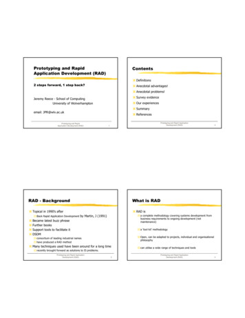
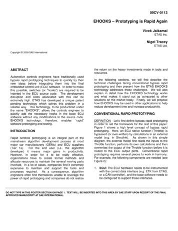
W I D PROTOTYPING: A PARADIGM SHIFT IN INVESTMENT CASTINGpattern (left),.Po1lymb n a t e5
RAPID PROTOWING: A PARADIGM SHIFI' IN INVES"CkX'ING6INVESTMENT CASTING RAPID PROTOTYPING PATTERNSQuickCastm Patterns in the Investment Casting ProcessAdvances in process development and the implementation of QuickCastTM software have had asignificant impact on applications for the SL process. Using the QuickCastTM build style andepoxy resin, it is now possible to,build semi-hollow patterns for investment casting (Figure 10).The combination of build style and epoxy resin material reduces the problem of thermal expansionduring bum-out by reducing the amount of resin in the pattern. With proper treatment, the semihollow patterns generate much less stress on the cel-dmic shell. As with any new manufacturingprocess, there are many variables associated with using QuickCastTM patterns as a replacement forqaditional wax patterns in investment casting. Our experience indicates that modifications totraditional lost-wax processing techniques such as pattern preparation, dipping, burn-out cycles,'and mold venting must be made to produce quality castings from QuickCastTM patterns. Whilethese recogmendations are not meant to be construed as the only successful methods for usingQuickCastTM patterns, our experiences have shown that our greatest successes have been with thefollowing procedures.The use of semi-hollow QuickCastTM patterns can be characterized by f i s t examining the steps intheir handling, then in how the mold is dewaxed and burned out. Most patterns require some handwork to prepare them for use as patterns. Sanding of stepped surfaces and removal of supportstructures are typically part of the process stream whether the SL parts are used as patterns or not.Being constructed from interlocking hollow cells allows the pattern to be drained; but all holes inthe pattern must be sealed prior to dipping, because any holes in the pattern will allow ceramicslurry to flow into the interior of the pattern resulting in extensive inclusions in the casting. Inaddition, any holes that resulted from sanding through the surface skin must be also be patched.Identification of holes is most easily made by pressure or vacuum testing the pattern.Once the pattern has been prepared, it is attached to a gating system. Whereas traditionalinvestment casters design the wax runners and gates to facilitate draining the melted wax out of themold in the autoclave (usually in a steam autoclave), the use of QuickCastTMpatterns places anadditional requirement on the wax distribution system. The dewax and bum-out step creates highpressures inside the pattern. While the polymer in the pattern interior has been removed, thepresence of air in the sealed pattern can be sufficient to cause a ballooning effect that is sufficient tocrack the shell. Venting of the pattern can be accomplished several ways. Hollow gates andrunners can be constructed and used to provide an unintempted gas path back up to the pouringcup. The hollow runner can also be vented to atmosphere at a location prior to attaching to thepouring cup. Individual vents, placed directly on the pattern can also be used. Regardless of howthe pattern is vented, it is critical to perforate the pattern at the location of the gate or vent, and thenseal the wax gate or stub directly over the hole. While it may seem contrary to previous advice thatdemanded that all holes in the pattern be sealed, if the pattern is not vented directly at specificlocations, then shell cracking via the ballooning effect is likely. The holes used to drain excessresin from the pattern have to be sealed, because generally they are not where the gates or ventswill be located. Unless all drain holes are sealed, smaller pinholes cannot be located by vacuum orpressure testing. By perforating the outer skin of the pattern and then sealing a wax gate or ventover the hole, the penetration of the pattern by ceramic slurry is precluded.After the ceramic mold is complete, it is necessary to remove the pattern and gating system fromthe mold. Using traditional dewaxing with a steam autoclave can be problematic for RP patterns.Autoclaving is designed to remove the majority of the wax from the mold, and subsequent bumout is then employed to eliminate the residual wax. Even after adding vents, our experience withautoclaving has yielded no consistent method to eliminate shell cracking. For this reason, theconsensus at Sandia, and indeed in industry, is that flash-fire dewaxing is the method of choice forc.
RAPID PROTOTYPING: A PARADIGM SHIFT IN INVESTMENT CASTING7RP pattern burnout. Special flash-fire furnaces designed specifically for burning out RP patternsare now available commercially.After the pattern is burned out, the mold will generally need to be patched. Any vents introducedearlier will need to be sealed with ceramic mortar. If the hollow gates and runners were vented upthrough the pour cup, then it would be possible to go directly to the casting operation from bumout. However, our experience with direct pouring is limited, since it is necessary to cool our moldsafter burn-out for inspection and patching. Individual choices for each foundry may depend on thetype of shell system being used and its tolerance for repeated thermal cycling as to whether or notseparate burn-out and casting pre-heat cycles can be used. Bum-out cycles for the patterns tend tobe higher than traditional processing. For example, bum-out of traditional autoclaved molds atSandia was conducted at 700OC ( 1 3 O O O F ) for 4 hours, but for SL patterns the bum-out temperatureis usually 930OC (17OoOF) or higher for periods extending to 8 hours or more. Experience withtemperatures as high as 1150OC ( 2 1 0 0 O F ) indicates that patterns can be fully combusted with littleor no ash residue in as little as 2 hours.Once the mold has been filled with metal, there is virtually no difference from the traditionalprocessing with maybe one exception. If the shell has been reinforced with fiber or is thicker thannormal, its removal may be slightly more difficult than normal.QTMPattern,SLS Patterns in the Investment Casting ProcessInvestment Casting WaxWhile SLS wax patterns could be processed identically to traditional injection molded waxpatterns, the reality of handling and finishing these fragile parts made their use difficult. Thisproblem was compounded in thin section parts. Eventually, the introduction of polycarbonate to
RAPID PROTOTYPING A PARADIGM SHIFI' IN INVESTMENT CASTING8SLS made the handling and finishing problems much less difficult. The discussion here will befocused on the use of polycarbonate patterns.PolycarbonatePolycarbonate patterns constructed in the Sinterstation are quite porous. Exact levels of porosityfor the patterns vary ,with build parameters, but this is generally not a critical factor in using thepatterns for investment casting. Since the patterns are porous, they must be sealed prior to dippingin ceramic slurry. Although the slurry-will not seep into the polycarbonate as it would through ahole in a QuickCastTMpattern, the colloidal silica binder in the facecoat seeps into the pattern,weakening the primary coats of the ceramic shell, resulting in a rough surface finish. -Hence, thestandard procedure for using these patterns is to soak the pattern in seal wax (an investment waxused for dipping gating systems to create a smooth surface) for enough time to allow the wax tothoroughly penetrate the polycarbonate. Although the wax is molten and the pattern heats to thetemperature of the wax (typically 19OoF), negligible distortion has been observed in the patterns.Upon removing the patterns from the wax dip tank, the excess wax is removed. The patterns arecooled back to room temperature and any excess wax is scraped from the surface. A heat gun isthen used to lightly melt the wax on the surface ofthe pattern. This melting "sweats" the wax up tothe surface and tends to smooth low areas between the polycarbonate particles. Extensive use ofthe heat gun will bring up too much wax to the surface, reducing dimensional accuracy of thepattern. Finally, the patterns are sanded or finished with an abrasive pad.,As with SL patterns, autoclaving tends to produce shell cracking; so its use is not recommended.Dkect bum-out is again the dewaxing method of choice. Since the patterns are not hollow,placement of gates and care in sealing holes is not an issue with polycarbonate SLS patterns, but . placement of vents is again important, Vents are routinely placed on patterns similarly to thatshown in Figure 11. The vents serve to provide air access to the pattern as it combusts to minimizethe amount of ash or carbonaceous residue in the mold. Unlike resin based SL patterns,polycarbonate is a thermoplastic and will tend to run out of the mold in a manner similar to wax. Itis substantially more viscous than wax and is not removed as quickly as wax. In most of thepatterns burned out at Sandia, about half of the polycarbonate runs out of the mold, with theremainder subject to combustion in the mold. The material that remains in the mold, especially inareas where it may collect or puddle, has been shown to attack shells. While the exact mechanismis uncertain, it is suspected that, like wax, the polycarbonate may to some extent soak into theshell, causing delamination of facecoat layers. The resulting surface of the casting has anappearance of a cracked desert lake-bed. Depending on orientation of the pattern, additional ventsin these re-entrant areas to assist with drainage are encouraged. Burn-out times with polycarbonatepatterns tend to be longer than with SL QuickCastTMpatterns. A typical bum-out cycle of soakingat 1600-180O0F until the primary combustion is complete, followed by 2-4 hours at 21OOOFgenerally removes all ash residue from the mold. If possible, excess air during the burn-out willhelp with removal of the ash residue in the mold.TrueForm PMmUnlike polycarbonate, TrueForm PM does not need to be dipped in wax to seal the surface prior toshelling. However, much Iike polycarbonate, TrueForm PMTMpatterns are approximately 70%dense. The reduced density is good for bum-out but may allow some very thin face coats to seepinto the surface of the part, causing a rough surface finish. Therefore, to improve the surfacefinish it may be necessary to apply a surface coating. DTM has developed a proprietarypolyurethane emulsion which can be used to fill surface porosity. This is done by dipping thepattern in the emulsion, then allowing it to dry. This surface treatment does not add measurablematerial to the surface but only fills in the pores. Other methods of sealing can also be used aslong as they are compatible with the TrueForm PMTMmaterial and the shelling process. The rest ofthe casting procedure for TrueForm PMTMpatterns is similar to that of polycarbonate. Patternsmade from this material have excellent feature definition, surface finish, and are significantly more
RAPID PROTOTYPING: A PARADIGM SHIFT IN INVESTMENT CASTING9accurate than patterns made frompolycarbonate. 'The increase in accuracy is pharily due to thelow shrink rate of the TrueForm PM material during the build process.;em attached
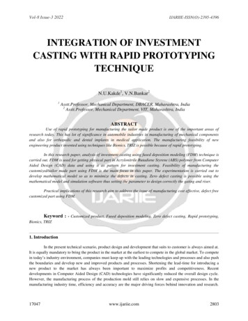
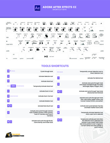
RAPID PROTO'IYPING: A PARADIGM Sm IN INVESTMENT CASTING10castingP& CAD file courtesy of Eastman Kodak Compaiy and is used as their bmchmark partDIMENSIONAL ACCURACY OF SL AND SLS PATTERNSInvestment castings can be only as accurate as the patterns from which they are produced. Patternsmade from SL and SLS machines continue to improve in both dimensional accuracy and surfacefinish. This improvement is directly related to process enhancements in software, hardware, andmaterials, as well as post processing techniques. For nearly three years, Sandia has used only SLand SLS processes to fabricate patterns to manufacture investment cast parts.In an effort to establish expected accuracy of patterns fabricated using SL and SLS processes,measurements of several patterns are documented from a benchmark part. The benchmark part is abicycle crank arm,Fig. 13, fabricated as part of a technology transfer program to support a smallmanufacturer of bicycle components. This part was first fabricated on the Sinterstation 2000 Betamachine in September 1992. Since then, it has been our de facto accuracy part. The geometricshape of the crank arm is representative of a part of average complexity. It has been fabricatedfrom a variety of materials including: investment casting wax, polycarbonate, True Form PMTM,acrylic polymer, epoxy (Aces), and epoxy (QuickCasFM).The measurement results of the SL acrylic, epoxy, Quickest 1.0, and QuickCast 1.1, (Fig. 14)and the SLS wax, polycarbonate, and TrueForm PMTMpatterns (Fig. 15) were taken after normalpost-processing techniques were used to remove support structures and other excess material afterthe parts were removed from the machine. These parts were measured in the metrology lab using aZeiss Coordinate Measuring Machine (CMM). A total of 21 diameters, twenty-one X-axis and Yaxis locations, 30 radius points, and 38 Z-axis measurements were taken from each part.This measurement data has been compiled over a four year period and is an update of previouslyreported data.
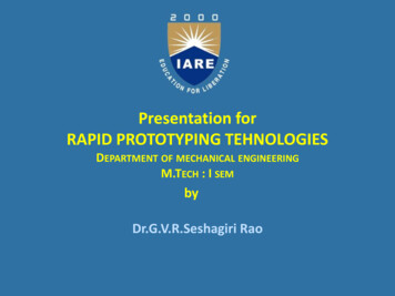
RAPID PROTOTYPING A PARADIGM Sm IN INVESTMENT CASTING11olluwlllsbnu aullu I l I v u G l atu, LLUIILIGU, 3 a u y i i model, SLQuickCast 1.1 pattern, SL ACES model, SLS wax pattern, and SLS polycarbonate pattern, SLSTrueForm patternA .VbV61UpII 1I;:I 1O.O2O0.0200.0160.010SLA ModeIs Average Deviation from NominalUIAMUL'EK0-0200.01 100.0000.000Manufacture Dak:A 2/8/93, B 3/22/93, C 3/24/93, E 6/27/93, F 6/29/93, g 3/1/94, H l1/27/94, J l1/29/94Acry Acrylic, QCl.O QuickCast 1.0, QCl.l QuickCast 1.1, ACES ACES Build Style, SL5180 ResinFigure 14 Measurement accuracy reported as deviation from nominal dimension forstereolithography patterns. Error bars represent 3s deviation.SLS Patterns Average Deviation from Nominal
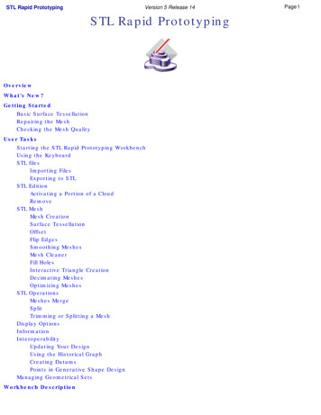
RAPID PROTOTYPING: A PARADIGM S0.0200.015T b.0100.00s0.0000'020 0.011DIAMETERO.O2O,,,12m IN INVESTMENT CASTING0.01s0.010Tf1. ,LINEARI II0.0100.000danufacture Date: A 9/4/92, B 9/14/92, C l1/15/92,1TF 5/31/96. *Fabricated on Sintcrstation Beta Machine, Wax Invesfment Casting Wax, Poly Polycarbonatc, TFTrueFonn PMFigure 15 Measurement accuracy reported as deviation from nominal dimension for selectivelaser sintered patterns. Error bars represent k s deviation.CONCLUSIONSThe development and implementation of 3D System's QuickCastTM build style and DTM'sTrueFormTMmaterial has had a significant impact on the overall quality of RP patterns used forinvestment casting. QuickCastTM has put to rest the debate over whether SL models could be usedas patterns for traditional investment casting. The accuracy and surface finish on patternsfabricated using this process have had (and will continue to have) a significant impact on theinvestment casting industry. Prototype and small-lot production parts are easily attainable withoutfabricating hard tooling.Sandia has been using the SLS process to fabricate patterns for investment casting since receivingthe SinterstationTM 2000 Beta machine in April, 1992. Beginning with wax and progressing topolycarbonate and TrueForm, the SLS process can now produce accurate patterns with very goodsurface finish. Requiring very little hands-on postprocessing further reduces both fabrication timeand the cost of pattern fabrication.Improvements and technological advances in Stereolithography, Selective Laser Sintering, andother rapid prototyping processes continue to be the driver for increasing the use of RP pattern bythe investment casting industry, not only for prototypes but for small-lot production parts. Now,any company that owns a Stereolithography apparatus or SinterstationTM2000 can make highquality patterns for investment casting metal parts.REFERENCES
aRAPID PROTOTYPING A PARADIGM SHIFT IN INVESTMENT CASTING131. “Integration of Rapid Prototyping Into Investment Casting,” Paper No. 23; C. L. Atwood, G .D. McCarty, B. T. Pardo; Sandia National Laboratories, presented at the 40th AnnualTechnical Meeting of the Investment Casting Institute (1992).2. “Integration of Rapid Prototyping Into Design and Manufacturing,” C. L. Atwood, G. D.Mccarty, B. T. Pardo, E. A. Bryce; Sandia National Laboratories, presented at the SME RapidPrototyping and Manufacturing ‘93 Conference.3. “Integration of Rapid Prototyping Into Product Development,” C. L. Atwood, G. D. McCarty,B. T. Pardo, E. A. Bryce, Sandia National Laboratories, presented at the Towards WorldClass Manufacturing 1993 Conference and subsequently published by IFIP North-Holland, M.J. Wozny, G. Olling, Editors, Copyright 1994.4. “Sandia National Laboratory - Accuracy Comparison,” Geoff Smith-Moritz, Editor,Prototyyin p Renort, September 1993.5 . “FASTCAST,” F. Zanner, C. Atwood, M. Maguire, R. Sikorski, D. Gartling, SandiaNational Laboratories, Sandia Technolopv EnTineering and Science Accomplishmenff, 1993.6 . “Implementing Rapid Prototyping at Sandia,” by C. L. Atwood, G. D. McCarty, B. T. Pardo,Edwin A. Bryce, Rapid Prototvnin? Svstems Fast Track to Product Realizatioq, Published bySociety of Manufacturing Engineers in cooperation with the Rapid Prototyping Association ofSME, Copyright 1994.7. “Rapid Prototyping Applications For Manufacturing,” by C. L. Atwood, M. C. Maguire, B. T.Pardo, E. A. Bryce, presented at 27th International SAMPE Technical Conference (1995).8. “RP&M Applications at Sandia National Laboratories,” by C. L. Atwood, M. C. Maguire, M.D. Baldwin, stereolithopraphy and other RP&M Technologie ,Principal author P. F. Jacobs,Published by Society of Manufacturing Engineers in cooperation with the Rapid PrototypingAssociation of SME, Copyright 1996.9 “Rapid Prototyping Technologies and Their Application to Metalcasting” by M. C. Maguire, M.D. Baldwin, C. L. Atwood, B. T. Pardo, American Metalcastin? Consom‘um, 1996.#
f RAPID PROTOTYPING A PARADIGM SHIFT IN INVESTMENT CASTING '2 required several gating and rigging design iterations (see Overview of Investment Casting Process). In an effort to speed the design and fabrication process of producing prototype castings and eliminate the need to procure wax injection tools, several processes were used.