Transcription
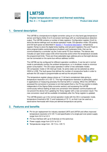
LM75BDigital temperature sensor and thermal watchdogRev. 6 — 11 August 2014Product data sheet1. General descriptionThe LM75B is a temperature-to-digital converter using an on-chip band gap temperaturesensor and Sigma-Delta A-to-D conversion technique with an overtemperature detectionoutput. The LM75B contains a number of data registers: Configuration register (Conf) tostore the device settings such as device operation mode, OS operation mode, OS polarityand OS fault queue as described in Section 7 “Functional description”; temperatureregister (Temp) to store the digital temp reading, and set-point registers (Tos and Thyst) tostore programmable overtemperature shutdown and hysteresis limits, that can becommunicated by a controller via the 2-wire serial I2C-bus interface. The device alsoincludes an open-drain output (OS) which becomes active when the temperature exceedsthe programmed limits. There are three selectable logic address pins so that eight devicescan be connected on the same bus without address conflict.The LM75B can be configured for different operation conditions. It can be set in normalmode to periodically monitor the ambient temperature, or in shutdown mode to minimizepower consumption. The OS output operates in either of two selectable modes:OS comparator mode or OS interrupt mode. Its active state can be selected as eitherHIGH or LOW. The fault queue that defines the number of consecutive faults in order toactivate the OS output is programmable as well as the set-point limits.The temperature register always stores an 11-bit two’s complement data giving atemperature resolution of 0.125 C. This high temperature resolution is particularly usefulin applications of measuring precisely the thermal drift or runaway. When the LM75B isaccessed the conversion in process is not interrupted (that is, the I2C-bus section is totallyindependent of the Sigma-Delta converter section) and accessing the LM75Bcontinuously without waiting at least one conversion time between communications willnot prevent the device from updating the Temp register with a new conversion result. Thenew conversion result will be available immediately after the Temp register is updated.The LM75B powers up in the normal operation mode with the OS in comparator mode,temperature threshold of 80 C and hysteresis of 75 C, so that it can be used as astand-alone thermostat with those pre-defined temperature set points.2. Features and benefits Pin-for-pin replacement for industry standard LM75 and LM75A and offers improvedtemperature resolution of 0.125 C and specification of a single part over power supplyrange from 2.8 V to 5.5 V I2C-bus interface with up to 8 devices on the same bus Power supply range from 2.8 V to 5.5 V Temperatures range from 55 C to 125 C
LM75BNXP SemiconductorsDigital temperature sensor and thermal watchdog Frequency range 20 Hz to 400 kHz with bus fault time-out to prevent hanging up thebus 11-bit ADC that offers a temperature resolution of 0.125 C Temperature accuracy of: 2 C from 25 C to 100 C 3 C from 55 C to 125 C Programmable temperature threshold and hysteresis set points Supply current of 1.0 A in shutdown mode for power conservation Stand-alone operation as thermostat at power-up ESD protection exceeds 4500 V HBM per JESD22-A114 and 1000 V CDM perJESD22-C101 Latch-up testing is done to JEDEC Standard JESD78 which exceeds 100 mA Small 8-pin package types: SO8, TSSOP8, 3 mm 2 mm XSON8U, and2 mm 3 mm HWSON83. Applications LM75BProduct data sheetSystem thermal managementPersonal computersElectronics equipmentIndustrial controllersAll information provided in this document is subject to legal disclaimers.Rev. 6 — 11 August 2014 NXP B.V. 2014. All rights reserved.2 of 37
LM75BNXP SemiconductorsDigital temperature sensor and thermal watchdog4. Ordering informationTable 1.Ordering tionVersionLM75BDLM75BDSO8plastic small outline package; 8 leads; body width 3.9 mmSOT96-1LM75BDPLM75BTSSOP8plastic thin shrink small outline package; 8 leads; body width 3 mmSOT505-1LM75BGD[1]75BXSON8Uplastic extremely thin small outline package; no leads; 8 terminals;UTLP based; body 3 2 0.5 mmSOT996-2LM75BTPM75HWSON8 plastic thermal enhanced very very thin small outline package;no leads; 8 terminals, 2 3 0.8 mm[1]SOT1069-2LM75BGD cannot be production cold temperature tested because of manufacturing process constraints. Although no LM75BGDcomplaints have been noted, NXP recommends consideration/use of the LM75BTP instead of the LM75BGD in operating environmentsof less than 0 C.4.1 Ordering optionsTable 2.Ordering optionsType numberOrderablepart numberPackagePacking 112SO8Standard marking * IC’s tube DSC bulk pack2000Tamb 55 C to 125 CLM75BD,118SO8Reel 13” Q1/T1*Standard mark SMD2500Tamb 55 C to 125 CLM75BDPLM75BDP,118TSSOP8Reel 13” Q1/T1*Standard mark SMD2500Tamb 55 C to 125 CLM75BGDLM75BGD,125XSON8UReel 7” Q3/T4 *Standard mark3000Tamb 55 C to 125 CLM75BTPLM75BTP,147HWSON8Reel 7” Q2/T3 *Standard mark4000Tamb 55 C to 125 CLM75BProduct data sheetAll information provided in this document is subject to legal disclaimers.Rev. 6 — 11 August 2014 NXP B.V. 2014. All rights reserved.3 of 37
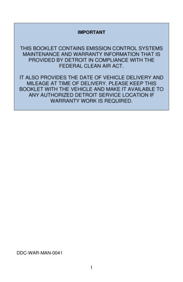
LM75BNXP SemiconductorsDigital temperature sensor and thermal watchdog5. Block diagramVCCLM75BBIASREFERENCEBAND GAPTEMP SCILLATORPOWER-ONRESETOSLOGIC CONTROL AND INTERFACE002aad453A2Fig 1.A1A0SCL SDAGNDBlock diagram of LM75B6. Pinning information6.1 2GND45A2LM75BDGND54002aad455002aad454Fig 2.LM75BDPPin configuration for SO8Fig 3.SDA18VCCSCL27A0OS36A1GND45A2Pin configuration for TSSOP8terminal 1index areaLM75BGDSDA1SCL2LM75BProduct data sheetA0OS36A1GND45A2002aag155Fig 5.All information provided in this document is subject to legal disclaimers.Rev. 6 — 11 August 20147Transparent top viewTransparent top viewPin configuration for XSON8UVCCLM75BTP002aae234Fig 4.8Pin configuration for HWSON8 NXP B.V. 2014. All rights reserved.4 of 37
LM75BNXP SemiconductorsDigital temperature sensor and thermal watchdog6.2 Pin descriptionTable 3.Pin descriptionSymbolPinDescriptionSDA1Digital I/O. I2C-bus serial bidirectional data line; open-drain.SCL2Digital input. I2C-bus serial clock input.OS3Overtemperature Shutdown output; open-drain.GND4Ground. To be connected to the system ground.A25Digital input. User-defined address bit 2.A16Digital input. User-defined address bit 1.A07Digital input. User-defined address bit 0.VCC8Power supply.7. Functional description7.1 General operationThe LM75B uses the on-chip band gap sensor to measure the device temperature withthe resolution of 0.125 C and stores the 11-bit two’s complement digital data, resultedfrom 11-bit A-to-D conversion, into the device Temp register. This Temp register can beread at any time by a controller on the I2C-bus. Reading temperature data does not affectthe conversion in progress during the read operation.The device can be set to operate in either mode: normal or shutdown. In normal operationmode, the temp-to-digital conversion is executed every 100 ms and the Temp register isupdated at the end of each conversion. During each ‘conversion period’ (Tconv) of about100 ms the device takes only about 10 ms, called ‘temperature conversion time’ (tconv(T)),to complete a temperature-to-data conversion and then becomes idle for the timeremaining in the period. This feature is implemented to significantly reduce the devicepower dissipation. In shutdown mode, the device becomes idle, data conversion isdisabled and the Temp register holds the latest result; however, the device I2C-businterface is still active and register write/read operation can be performed. The deviceoperation mode is controllable by programming bit B0 of the configuration register. Thetemperature conversion is initiated when the device is powered-up or put back into normalmode from shutdown.In addition, at the end of each conversion in normal mode, the temperature data (or Temp)in the Temp register is automatically compared with the overtemperature shutdownthreshold data (or Tth(ots)) stored in the Tos register, and the hysteresis data (or Thys)stored in the Thyst register, in order to set the state of the device OS output accordingly.The device Tos and Thyst registers are write/read capable, and both operate with 9-bittwo’s complement digital data. To match with this 9-bit operation, the Temp register usesonly the 9 MSB bits of its 11-bit data for the comparison.The way that the OS output responds to the comparison operation depends upon the OSoperation mode selected by configuration bit B1, and the user-defined fault queue definedby configuration bits B3 and B4.LM75BProduct data sheetAll information provided in this document is subject to legal disclaimers.Rev. 6 — 11 August 2014 NXP B.V. 2014. All rights reserved.5 of 37
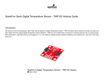
LM75BNXP SemiconductorsDigital temperature sensor and thermal watchdogIn OS comparator mode, the OS output behaves like a thermostat. It becomes activewhen the Temp exceeds the Tth(ots), and is reset when the Temp drops below the Thys.Reading the device registers or putting the device into shutdown does not change thestate of the OS output. The OS output in this case can be used to control cooling fans orthermal switches.In OS interrupt mode, the OS output is used for thermal interruption. When the device ispowered-up, the OS output is first activated only when the Temp exceeds the Tth(ots); thenit remains active indefinitely until being reset by a read of any register. Once the OS outputhas been activated by crossing Tth(ots) and then reset, it can be activated again only whenthe Temp drops below the Thys; then again, it remains active indefinitely until being resetby a read of any register. The OS interrupt operation would be continued in this sequence:Tth(ots) trip, Reset, Thys trip, Reset, Tth(ots) trip, Reset, Thys trip, Reset, etc. Putting thedevice into the shutdown mode by setting the bit 0 of the configuration register also resetsthe OS output.In both cases, comparator mode and interrupt mode, the OS output is activated only if anumber of consecutive faults, defined by the device fault queue, has been met. The faultqueue is programmable and stored in the two bits, B3 and B4, of the Configurationregister. Also, the OS output active state is selectable as HIGH or LOW by settingaccordingly the configuration register bit B2.At power-up, the device is put into normal operation mode, the Tth(ots) is set to 80 C, theThys is set to 75 C, the OS active state is selected LOW and the fault queue is equal to 1.The temp reading data is not available until the first conversion is completed in about100 ms.The OS response to the temperature is illustrated in Figure 6.Tth(ots)Thysreading temperature limitsOS resetOS activeOS output in comparator modeOS reset(1)(1)(1)OS activeOS output in interrupt mode002aae334(1) OS is reset by either reading register or putting the device in shutdown mode. It is assumed thatthe fault queue is met at each Tth(ots) and Thys crossing point.Fig 6.LM75BProduct data sheetOS response to temperatureAll information provided in this document is subject to legal disclaimers.Rev. 6 — 11 August 2014 NXP B.V. 2014. All rights reserved.6 of 37
LM75BNXP SemiconductorsDigital temperature sensor and thermal watchdog7.2 I2C-bus serial interfaceThe LM75B can be connected to a compatible 2-wire serial interface I2C-bus as a slavedevice under the control of a controller or master device, using two device terminals, SCLand SDA. The controller must provide the SCL clock signal and write/read data to/from thedevice through the SDA terminal. Notice that if the I2C-bus common pull-up resistors havenot been installed as required for I2C-bus, then an external pull-up resistor, about 10 k ,is needed for each of these two terminals. The bus communication protocols aredescribed in Section 7.10.7.2.1 Bus fault time-outIf the SDA line is held LOW for longer than tto (75 ms minimum / 13.3 Hz; guaranteed at50 ms minimum / 20 Hz), the LM75B will reset to the idle state (SDA released) and waitfor a new START condition. This ensures that the LM75B will never hang up the busshould there be conflict in the transmission sequence.7.3 Slave addressThe LM75B slave address on the I2C-bus is partially defined by the logic applied to thedevice address pins A2, A1 and A0. Each of them is typically connected either to GND forlogic 0, or to VCC for logic 1. These pins represent the three LSB bits of the device 7-bitaddress. The other four MSB bits of the address data are preset to ‘1001’ by hard wiringinside the LM75B. Table 4 shows the device’s complete address and indicates that up to8 devices can be connected to the same bus without address conflict. Because the inputpins, SCL, SDA and A2 to A0, are not internally biased, it is important that they should notbe left floating in any application.Table 4.Address table1 HIGH; 0 LOW.MSB1LSB001A2A1A07.4 Register listThe LM75B contains four data registers beside the pointer register as listed in Table 5.The pointer value, read/write capability and default content at power-up of the registersare also shown in Table 5.LM75BProduct data sheetTable 5.Register nConf01hR/W00hConfiguration register: contains a single 8-bit databyte; to set the device operating condition; default 0.Temp00hread onlyn/aTemperature register: contains two 8-bit data bytes;to store the measured Temp data.Tos03hR/W5000hOvertemperature shutdown threshold register:contains two 8-bit data bytes; to store theovertemperature shutdown Tth(ots) limit;default 80 C.Thyst02hR/W4B00hHysteresis register: contains two 8-bit data bytes;to store the hysteresis Thys limit; default 75 C.All information provided in this document is subject to legal disclaimers.Rev. 6 — 11 August 2014 NXP B.V. 2014. All rights reserved.7 of 37
LM75BNXP SemiconductorsDigital temperature sensor and thermal watchdog7.4.1 Pointer registerThe Pointer register contains an 8-bit data byte, of which the two LSB bits represent thepointer value of the other four registers, and the other 6 MSB bits are equal to 0, as shownin Table 6 and Table 7. The Pointer register is not accessible to the user, but is used toselect the data register for write/read operation by including the pointer data byte in thebus command.Table 6.Pointer registerB7B6B5B4B3B2B[1:0]000000pointer valueTable 7.Pointer valueB1B0Selected register00Temperature register (Temp)01Configuration register (Conf)10Hysteresis register (Thyst)11Overtemperature shutdown register (Tos)Because the Pointer value is latched into the Pointer register when the bus command(which includes the pointer byte) is executed, a read from the LM75B may or may notinclude the pointer byte in the statement. To read again a register that has been recentlyread and the pointer has been preset, the pointer byte does not have to be included. Toread a register that is different from the one that has been recently read, the pointer bytemust be included. However, a write to the LM75B must always include the pointer byte inthe statement. The bus communication protocols are described in Section 7.10.At power-up, the Pointer value is equal to 00 and the Temp register is selected; users canthen read the Temp data without specifying the pointer byte.7.4.2 Configuration registerThe Configuration register (Conf) is a write/read register and contains an 8-bitnon-complement data byte that is used to configure the device for different operationconditions. Table 8 shows the bit assignments of this register.Table 8.Conf registerLegend: * default value.BitSymbolAccess Value DescriptionB[7:5]reservedR/WB[4:3]OS F QUE[1:0] R/WB2LM75BProduct data sheetOS POL000*reserved for manufacturer’s use; should be kept aszeroes for normal operationOS fault queue programming00*queue value 101queue value 210queue value 411queue value 6R/WOS polarity selection0*OS active LOW1OS active HIGHAll information provided in this document is subject to legal disclaimers.Rev. 6 — 11 August 2014 NXP B.V. 2014. All rights reserved.8 of 37
LM75BNXP SemiconductorsDigital temperature sensor and thermal watchdogTable 8.Conf register continuedLegend: * default value.BitSymbolAccess Value DescriptionB1OS COMP INT R/WOS operation mode selection0*OS comparator1B0SHUTDOWNOS interruptR/Wdevice operation mode selection0*normal1shutdown7.4.3 Temperature registerThe Temperature register (Temp) holds the digital result of temperature measurement ormonitor at the end of each analog-to-digital conversion. This register is read-only andcontains two 8-bit data bytes consisting of one Most Significant Byte (MSByte) and oneLeast Significant Byte (LSByte). However, only 11 bits of those two bytes are used to storethe Temp data in two’s complement format with the resolution of 0.125 C. Table 9 showsthe bit arrangement of the Temp data in the data bytes.Table 9.Temp 4D3D2D1D0XXXXXWhen reading register Temp, all 16 bits of the two data bytes (MSByte and LSByte) areprovided to the bus and must be all collected by the controller to complete the busoperation. However, only the 11 most significant bits should be used, and the 5 leastsignificant bits of the LSByte are zero and should be ignored. One of the ways to calculatethe Temp value in C from the 11-bit Temp data is:1. If the Temp data MSByte bit D10 0, then the temperature is positive and Temp value( C) (Temp data) 0.125 C.2. If the Temp data MSByte bit D10 1, then the temperature is negative andTemp value ( C) (two’s complement of Temp data) 0.125 C.Examples of the Temp data and value are shown in Table 10.Table 10.LM75BProduct data sheetTemp register value11-bit binary(two’s complement)Hexadecimal valueDecimal valueValue011 1111 10003F81016 127.000 C011 1111 01113F71015 126.875 C011 1111 00013F11009 126.125 C011 1110 10003E81000 125.000 C000 1100 10000C8200 25.000 C000 0000 00010011 0.125 C000 0000 000000000.000 C111 1111 11117FF 1 0.125 CAll information provided in this document is subject to legal disclaimers.Rev. 6 — 11 August 2014 NXP B.V. 2014. All rights reserved.9 of 37
LM75BNXP SemiconductorsDigital temperature sensor and thermal watchdogTable 10.Temp register value continued11-bit binary(two’s complement)Hexadecimal valueDecimal valueValue111 0011 1000738 200 25.000 C110 0100 1001649 439 54.875 C110 0100 1000648 440 55.000 CFor 9-bit Temp data application in replacing the industry standard LM75, just use only9 MSB bits of the two bytes and disregard 7 LSB of the LSByte. The 9-bit Temp data with0.5 C resolution of the LM75B is defined exactly in the same way as for the standardLM75 and it is here similar to the Tos and Thyst registers.The only MSByte of the temperature can also be read with the use of a one-byte readingcommand. Then the temperature resolution will be 1.00 C instead.7.4.4 Overtemperature shutdown threshold (Tos) and hysteresis (Thyst) registersThese two registers, are write/read registers, and also called set-point registers. They areused to store the user-defined temperature limits, called overtemperature shutdownthreshold (Tth(ots)) and hysteresis temperature (Thys), for the device watchdog operation.At the end of each conversion the Temp data will be compared with the data stored inthese two registers in order to set the state of the device OS output; see Section 7.1.Each of the set-point registers contains two 8-bit data bytes consisting of one MSByte andone LSByte the same as register Temp. However, only 9 bits of the two bytes are used tostore the set-point data in two’s complement format with the resolution of 0.5 C. Table 11and Table 12 show the bit arrangement of the Tos data and Thyst data in the data bytes.Notice that because only 9-bit data are used in the set-point registers, the device usesonly the 9 MSB of the Temp data for data comparison.Table 11.Tos D1D0XXXXXXXTable 12.Thyst D1D0XXXXXXXWhen a set-point register is read, all 16 bits are provided to the bus and must be collectedby the controller to complete the bus operation. However, only the 9 most significant bitsshould be used and the 7 LSB of the LSByte are equal to zero and should be ignored.Table 13 shows examples of the limit data and value.LM75BProduct data sheetAll information provided in this document is subject to legal disclaimers.Rev. 6 — 11 August 2014 NXP B.V. 2014. All rights reserved.10 of 37
LM75BNXP SemiconductorsDigital temperature sensor and thermal watchdogTable 13.Tos and Thyst limit data and value11-bit binary(two’s complement)Hexadecimal valueDecimal valueValue0 1111 10100FA250 125.0 C0 0011 001003250 25.0 C0 0000 00010011 0.5 C0 0000 000000000.0 C1 1111 11111FF 1 0.5 C1 1100 11101CE 50 25.0 C1 1001 0010192 110 55.0 C7.5 OS output and polarityThe OS output is an open-drain output and its state represents results of the devicewatchdog operation as described in Section 7.1. In order to observe this output state, anexternal pull-up resistor is needed. The resistor should be as large as possible, up to200 k , to minimize the Temp reading error due to internal heating by the high OS sinkingcurrent.The OS output active state can be selected as HIGH or LOW by programming bit B2(OS POL) of register Conf: setting bit OS POL to logic 1 selects OS active HIGH andsetting bit B2 to logic 0 sets OS active LOW. At power-up, bit OS POL is equal to logic 0and the OS active state is LOW.7.6 OS comparator and interrupt modesAs described in Section 7.1, the device OS output responds to the result of thecomparison between register Temp data and the programmed limits, in registers Tos andThyst, in different ways depending on the selected OS mode: OS comparator orOS interrupt. The OS mode is selected by programming bit B1 (OS COMP INT) ofregister Conf: setting bit OS COMP INT to logic 1 selects the OS interrupt mode, andsetting to logic 0 selects the OS comparator mode. At power-up, bit OS COMP INT isequal to logic 0 and the OS comparator is selected.The main difference between the two modes is that in OS comparator mode, the OSoutput becomes active when Temp has exceeded Tth(ots) and reset when Temp hasdropped below Thys, reading a register or putting the device into shutdown mode does notchange the state of the OS output; while in OS interrupt mode, once it has been activatedeither by exceeding Tth(ots) or dropping below Thys, the OS output will remain activeindefinitely until reading a register, then the OS output is reset.Temperature limits Tth(ots) and Thys must be selected so that Tth(ots) Thys. Otherwise, theOS output state will be undefined.LM75BProduct data sheetAll information provided in this document is subject to legal disclaimers.Rev. 6 — 11 August 2014 NXP B.V. 2014. All rights reserved.11 of 37
LM75BNXP SemiconductorsDigital temperature sensor and thermal watchdog7.7 OS fault queueFault queue is defined as the number of faults that must occur consecutively to activatethe OS output. It is provided to avoid false tripping due to noise. Because faults aredetermined at the end of data conversions, fault queue is also defined as the number ofconsecutive conversions returning a temperature trip. The value of fault queue isselectable by programming the two bits B4 and B3 (OS F QUE[1:0]) in register Conf.Notice that the programmed data and the fault queue value are not the same. Table 14shows the one-to-one relationship between them. At power-up, fault queue data 0 andfault queue value 1.Table 14.Fault queue tableFault queue dataFault queue valueOS F QUE[1]OS F QUE[0]Decimal0010121041167.8 Shutdown modeThe device operation mode is selected by programming bit B0 (SHUTDOWN) of registerConf. Setting bit SHUTDOWN to logic 1 will put the device into shutdown mode. Resettingbit SHUTDOWN to logic 0 will return the device to normal mode.In shutdown mode, the device draws a small current of approximately 1.0 A and thepower dissipation is minimized; the temperature conversion stops, but the I2C-businterface remains active and register write/read operation can be performed. When theshutdown is set, the OS output will be unchanged in comparator mode and reset ininterrupt mode.7.9 Power-up default and power-on resetThe LM75B always powers-up in its default state with: Normal operation modeOS comparator modeTth(ots) 80 CThys 75 COS output active state is LOWPointer value is logic 00 (Temp)When the power supply voltage is dropped below the device power-on reset level ofapproximately 1.0 V (POR) for over 2 s and then rises up again, the device will be resetto its default condition as listed above.LM75BProduct data sheetAll information provided in this document is subject to legal disclaimers.Rev. 6 — 11 August 2014 NXP B.V. 2014. All rights reserved.12 of 37
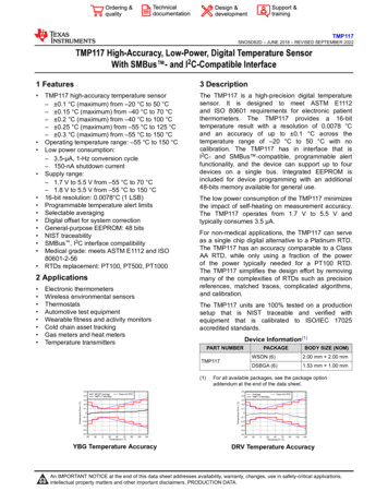
LM75BNXP SemiconductorsDigital temperature sensor and thermal watchdog7.10 Protocols for writing and reading the registersThe communication between the host and the LM75B must strictly follow the rules asdefined by the I2C-bus management. The protocols for LM75B register read/writeoperations are illustrated in Figure 7 to Figure 12 together with the following definitions:1. Before a communication, the I2C-bus must be free or not busy. It means that the SCLand SDA lines must both be released by all devices on the bus, and they becomeHIGH by the bus pull-up resistors.2. The host must provide SCL clock pulses necessary for the communication. Data istransferred in a sequence of 9 SCL clock pulses for every 8-bit data byte followed by1-bit status of the acknowledgement.3. During data transfer, except the START and STOP signals, the SDA signal must bestable while the SCL signal is HIGH. It means that the SDA signal can be changedonly during the LOW duration of the SCL line.4. S: START signal, initiated by the host to start a communication, the SDA goes fromHIGH to LOW while the SCL is HIGH.5. RS: RE-START signal, same as the START signal, to start a read command thatfollows a write command.6. P: STOP signal, generated by the host to stop a communication, the SDA goes fromLOW to HIGH while the SCL is HIGH. The bus becomes free thereafter.7. W: write bit, when the write/read bit LOW in a write command.8. R: read bit, when the write/read bit HIGH in a read command.9. A: device acknowledge bit, returned by the LM75B. It is LOW if the device worksproperly and HIGH if not. The host must release the SDA line during this period inorder to give the device the control on the SDA line.10. A’: master acknowledge bit, not returned by the device, but set by the master or hostin reading 2-byte data. During this clock period, the host must set the SDA line toLOW in order to notify the device that the first byte has been read for the device toprovide the second byte onto the bus.11. NA: Not Acknowledge bit. During this clock period, both the device and host releasethe SDA line at the end of a data transfer, the host is then enabled to generate theSTOP signal.12. In a write protocol, data is sent from the host to the device and the host controls theSDA line, except during the clock period when the device sends the deviceacknowledgement signal to the bus.13. In a read protocol, data is sent to the bus by the device and the host must release theSDA line during the time that the device is providing data onto the bus and controllingthe SDA line, except during the clock period when the master sends the masteracknowledgement signal to the bus.LM75BProduct data sheetAll information provided in this document is subject to legal disclaimers.Rev. 6 — 11 August 2014 NXP B.V. 2014. All rights reserved.13 of 37
LM75BNXP SemiconductorsDigital temperature sensor and thermal 9SCLSDASA2 A1 A0 WAdevice addressSTARTpointer bytewritePconfiguration data bytedeviceacknowledgedeviceacknowledgeFig 7.D4 D3 D2 D1 D0 AdeviceacknowledgeSTOP001aad624Write configuration register (1-byte data)123456789123456789(next)SCLSDAS1001A2A1A0 W0A00device address00001ARS (next)pointer eviceacknowledgewrite89A0 RA123456789SCL (cont.)SDA (cont.)D7 D6 D5 D4 D3 D2 D1 D0 NAdevice addressdata byte from deviceSTOPmaster notacknowledgedreaddeviceacknowledgeFig 8.P001aad625Read configuration register including pointer byte (1-byte data)12345671001A2A189A0 RA123456789SCLSDASdevice addressSTARTD7 D6 D5 D4 D3 D2 D1 D0 NAdata byte from devicereaddeviceacknowledgeFig 9.Pmaster notacknowledgedSTOP001aad626Read configuration or temp register with preset pointer (1-byte data)LM75BProduct data sheetAll information provided in this document is subject to legal disclaimers.Rev. 6 — 11 August 2014 NXP B.V. 2014. All rights reserved.14 of 37
LM75BNXP SemiconductorsDigital temperature sensor and thermal A000device edgewrite2P1pointer byteSTART1056789123456789SCL (cont.)SDA (cont.)D7 D6 D5 D4 D3 D2 D1 D0 AD7 D6 D5 D4 D3 D2 D1 D0MSByte dataAPLSByte 6Fig 10. Write Tos or Thyst register (2-byte data)1234567891234567890SCLSDA(next)S1001A2 A1 A0 W A00device addressSTART0000P1 P0 A RS (next)pointer byte1234deviceacknowledge5 6 7 81001A2 A1 A0 9SCL (cont)SDA (cont)D7 D6 D5 D4 D3 D2 D1 D0 A'device addressD7 D6 D5 D4 D3 D2 D1 D0 NAMSByte from deviceLSByte from devicemasteracknowledgereaddeviceacknowledgePSTOP
SDA 1 Digital I/O. I2C-bus serial bidirectional data line; open-drain. SCL 2 Digital input. I2C-bus serial clock input. OS 3 Overtemperature Shutdown output; open-drain. GND 4 Ground. To be connected to the system ground. A2 5 Digital input. User-defined address bit 2. A1 6 Digital input. User-defined address bit 1. A0 7 Digital input.