Transcription
950/1025/1050/1055950 ProRacerComputer Wheel BalancersService Manual andTroubleshooting GuideP.O. Box 3002, 1601 J. P. Hennessy Drive, LaVergne, TN USA 37086 615/641-7533 800/688-6359HENNESSY INDUSTRIES INC. Manufacturer of AMMCO , COATS and BADA Automotive Service Equipment and Tools.Manual Part:9111123 03Revision: 11/05
Direct Driveii Service Manual — COATS Models 950/950 ProRacer/1025/1050/1055
ContentsIntroduction . . . . . . . . . . . . . . . . . . . . .Safety Notes . . . . . . . . . . . . . . . . . . . .Servicing . . . . . . . . . . . . . . . . . . . . . . .Equipment Needed . . . . . . . . . . . . . . .Voltage & Phase Checking ProcedurePreliminary Inspection . . . . . . . . . . . .Functional Checks.1.1.1.1.2.3Operational Check . . . . . . . . . . . . . . . . . . . . . . . . . . .3Accuracy Check (Plane Separation) . . . . . . . . . . . .3 - 4Rotational Check (Use a Hub Centric Wheel) . . . . . . .4Calibration ProceduresWeight Sensor Calibration . . . . . . . . . . . . . . . . . . . . .4A & D Arm Calibration (Code 10) . . . . . . . . . . . . . .4 - 5Stop-On-Top Calibration (Code 20/21) . . . . . . . . . . . .5*Distance Gauge Tape Placement (Optimize A) . . . . .5Error Codes . . . . . . . . . . . . . . . . . . . . . . . . .5 - 6*Function Codes . . . . . . . . . . . . . . . . . . . . . .6 - 7Troubleshooting Section for Models 950, 1025,1050, & 1055 Balancers . . . . . . . . . . . . . . .7 - 16Introduction . . . . . . . . . . . . . . . . . . . . . . . . . . . . . . . .7Fan Motor Does Not Run (Contactor Model) . . . . . . .8Accuracy Problems (Plane Separation) . . . . . . . . . . . .8Rotational Problems (Contractor & MotorController Model) . . . . . . . . . . . . . . . . . . . . . . . . . . .9Repeatability Problems (Contractor & MotorController Model) . . . . . . . . . . . . . . . . . . . . . . . . . . .10Display Does Not Light (Contactro Model) . . . . . . . .11Balancer Does Not Cycle (Contactor Model) . . .12 - 13Balancer Does Not Brake (Contactor Model) . . .14 - 15A & D Arm Problems . . . . . . . . . . . . . . . . . . . . . . . .16Checking Procedures*Bridge Rectifiers . . . . . . . . . . . . . . . . . . . . . . . . . .17*Optical Encoder (Code 44) . . . . . . . . . . . . . . . . . . .17*Motor Circuit Testing . . . . . . . . . . . . . . . . . . . . . . .17*Motor Circuit Diagram . . . . . . . . . . . . . . . . . . . . . .18*Piezo Output . . . . . . . . . . . . . . . . . . . . . . . . . . . . .19Replacement Procedures Section for Models950, 1025, 1050, & 1055 Balancers . . . . . .20 - 25Front Panel/Printed Circuit Board Assembly . . . . . . .20Contactor Coil Resistance Measurement . . . . . . . . .20Front Panel/Printed Circuit Board AssemblyReplacement . . . . . . . . . . . . . . . . . . . . . . . . . . . . . .20Touch Panel/Aluminum Back Panel and PCB Assembly . . . .20Hood Magnet . . . . . . . . . . . . . . . . . . . . . . . . . . . . .21Magnetic Hood Switch . . . . . . . . . . . . . . . . . . . . . .21*Mechanical Hood/Interlock Switch . . . . . . . . . . . . .21On/Off Switch . . . . . . . . . . . . . . . . . . . . . . . . . . . . .21Circuit Breakers . . . . . . . . . . . . . . . . . . . . . . . . . . . .21Transformer . . . . . . . . . . . . . . . . . . . . . . . . . . . . . . .22Contactor . . . . . . . . . . . . . . . . . . . . . . . . . . . . . . . .22Auxiliary Contactor Block . . . . . . . . . . . . . . . . . . . . .22Bridge Rectifiers . . . . . . . . . . . . . . . . . . . . . . . . . . .22A & D Arm Assembly . . . . . . . . . . . . . . . . . . . . . . .23Fan Motor Assembly . . . . . . . . . . . . . . . . . . . . . . . .23Rotary Shutter . . . . . . . . . . . . . . . . . . . . . . . . . . . . .23Optical Encoder Assembly . . . . . . . . . . . . . . . . . . . .23Drive Motor Assembly . . . . . . . . . . . . . . . . . . . . . . .24Piezo Assembly . . . . . . . . . . . . . . . . . . . . . . . .24 - 25Capacitor Assembly . . . . . . . . . . . . . . . . . . . . . . . . .25Capacitor . . . . . . . . . . . . . . . . . . . . . . . . . . . . . . . . .25Signal Harness . . . . . . . . . . . . . . . . . . . . . . . . . . . .25Repair Procedures for the A & D Arm AssemblyA Pulley Removal . . . . . . . . . . . . . . . . . .A Pulley Installation/Adjustment (Code 10)A Potentiometer Replacement . . . . . . . . .D Pulley Removal . . . . . . . . . . . . . . . . . .D Pulley Installation/Adjustment (Code 10)D Potentiometer Replacement . . . . . . . . .26.26.26.26.27.27*Motor Service Kit Instructions . . . . . . . . . . .28*950 Pro Racer . . . . . . . . . . . . . . . . . . . . . . . . .28*950 Pro Racer Wiring Diagram . . . . . . . . . . . . . . . .29*950 Wiring Diagram (Contactor Style) . . . . .30*1050 Wiring Diagram (Contactor Style) . . . .31*Solid State Wiring Diagrams &Troubleshooting Guides . . . . . . . . . . . . . . . . .32For units produced after 1/1/98 . . . . . . . . . . .Mechanical Hood Switches . . . . . . . . . . . . . .Mechanical Hood Switch Diagram . . . . . . . . .*1050 Wiring Diagram (Motor ControllerStyle/Magnetic Switches) . . . . . . . . . . . . . . .*1050 Wiring Diagram (Motor ControllerStyle/Mechanical Switches) . . . . . . . . . . . . . .*Motor Controller Test Box #8112708 . . . . . .*Display Does Not Light (Solid State MotorController Model) . . . . . . . . . . . . . . . . . . . . .*Balancer Does Not Cycle (Solid State MotorController Model) . . . . . . . . . . . . . . . . . . . . .*Balancer Does Not Brake (Solid State MotorController Model) . . . . . . . . . . . . . . . . . . . . . . . . .32. . . . .32. . . . .33. . . . .34. . . . .36. . . . .38. . . . .39. . . . .40. . . . .41*PCB Checklist Addendum . . . . . . . . . . . . . . .42Diode Test . . . . . . . . . . . . . . . . . . . . . . . . . . . . . . . .42IC Test . . . . . . . . . . . . . . . . . . . . . . . . . . . . . . . . . . .42*Glossary of Terms . . . . . . . . . . . . . . . . . . . . .43*This manual has been updated to include all relatedmodels. Items that are new are high lighted by an asterick(*) for your convenience.Service Manual — COATS Models 950/950 ProRacer/1025/1050/1055 iii
SafetyIMPORTANT SAFETY INSTRUCTIONSREAD ALL INSTRUCTIONS1.Eye and face protection recommendations:“Protective eye and face equipment is required tobe used where there is a reasonable probability ofinjury that can be prevented by the use of suchequipment.” O.S.H.A. 1910.133(a) Protective goggles, safety glasses, or a face shield must be provided by the owner and worn by the operator ofthe equipment. Care should be taken to see thatall eye and face safety precautions are followed bythe operator. ALWAYS WEAR SAFETY GLASSES.Everyday glasses only have impact resistantlenses, they are not safety glasses.2. Do not disable hood safety interlock system, or inany way shortcut safety controls and operations.3. Be sure that wheels are mounted properly, thehub nut engages the arbor for not less than four(4) turns, and the hub nut is firmly tightenedbefore spinning the wheel.4. Read and understand this manual before operating. Abuse and misuse will shorten the functionallife.5. Be sure the balancer is properly connected to thepower supply and electrically grounded.6. Do not operate equipment with a damaged cordor if the equipment has been dropped or damaged– until it has been examined by a qualified serviceman.7.Do not let cord hang over edge of table, bench, orcounter or come in contact with hot manifolds ormoving fan blades.8. If an extension cord is necessary, a cord with acurrent rating equal to or more than that of theequipment should be used. Cords rated for lesscurrent than the equipment may overheat. Careshould be taken to arrange the cord so that it willnot be tripped over or pulled.10. Wear proper clothing. Safety toe, non-slipfootwear and protective hair covering to containhair is recommended. Do not wear jewelry, looseclothing, neckties, or gloves when operating thebalancer.11. Keep work area clean and well lighted. Clutteredand/or dark areas invite accidents.12. Avoid dangerous environments. Do not use powertools or electrical equipment in damp or wet locations, or expose them to rain.13. Avoid unintentional starting. Be sure the balanceris turned off before servicing.14. Disconnect the balancer before servicing.15. Use only manufacturer’s recommended accessories. Improper accessories may result in personal injury or property damage.16. Repair or replace any part that is damaged or wornand that may cause unsafe balancer operation. Donot operate damaged equipment until it has beenexamined by a qualified service technician.17. Never overload or stand on the balancer.18. Do not allow untrained persons to operatemachinery.19. To reduce the risk of fire, do not operate equipment in the vicinity of open containers or flammable liquids (gasoline).20. Adequate ventilation should be provided whenworking on operating internal combustionengines.21. Keep hair, loose clothing, fingers, and all parts ofbody away from moving parts.22. Use equipment only as described in this manual.23. Use only manufacturer’s recommended attachments.9. Keep guards and safety features in place and inworking order.SAVE THESE INSTRUCTIONSiv Service Manual — COATS Models 950/950 ProRacer/1025/1050/1055
Direct DriveIntroductionServicingThis service manual contains the functional checks,troubleshooting, adjustment, and part replacementinstructions for COATS Models 950, 950 Pro Racer,1025,1050 and 1055 Wheel Balancers. Exploded views,illustrations, and an indexed parts list facilitate partslocation, ordering, and replacement. All adjustmentsand replacements can be rendered with mechanic's orelectrician's tools.Service should be performed only by COATS trainedand authorized service personnel. The troubleshootingand service procedures in this manual are arranged toallow rapid and thorough service. The steps are preliminary inspection, functional checks, repair of failure,replacement or adjustment, and functional checks.Identification of replacement parts required can beaccomplished by using the pictorial breakdown andindex in this manual. It is important that the functionalchecks be performed in sequence and the problem isolated prior to attempting any adjustments or replacements. If an adjustment or replacement is made, theentire functional checks must be performed successfully before the balancer can be considered available forservice.Safety NotesHigh voltages, high torque motors, and high speedrotating wheels are present in coats wheel balancers.Follow the safety rules below while servicing a balancer:1. Disconnect balancer from power source beforestarting any part replacement or internal adjustment.2. Lower guard hood before starting cycle.3. Do not wear neckties or loose clothing while servicing the balancer.4. Be aware of hair length. If hair is long, wear it upunder a hat.5. Mounting cones must be centered in wheel beforetightening. The wheel must be forced up firmly againstthe faceplate. The hub nut must be engaged by a minimum of four (4) full threads. Tighten hub nut by rotatingthe wheel and striking a spoke of the hub nut with theheel of the hand. Failure to tighten the hub nut couldresult in serious injury.Equipment Needed1. AC - DC / Volt - Ohm meter.2. Test Wheel - Domestic 14, 15 or 16-inch diameterx 6 - 6 1/2-inch wide steel wheel with a center holesuitable for mounting with a back cone. A new 70series tire properly mounted and inflated, balanced towithin 0.05 ounces should be part of this wheelassembly. The lateral run out of this wheelshould be less than 1/8".3. Mechanic's and electrician's tools.4. Thread locking anaerobic (Loctite 242 or equivalent).5. Retaining compound (Loctite 601 or equivalent).6. Dial indicator (runout gauge) with magnetic base,Starret No. 25-431 or equivalent.7. Modeling Clay.8. Motor Controller PCB tester (# 8112708)9. *Membrane Touch Panel Tester (8112929)Service Manual — COATS Models 950/950 ProRacer/1025/1050/1055 1
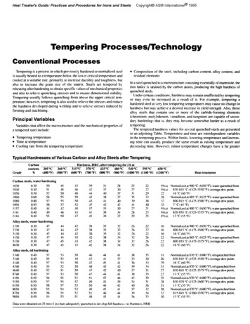
Direct DriveVoltage & Phase CheckingProcedure4. Plug the balancer to a power source.1. Unplug the Balancer from the power source.2. Perform all voltage checks shown in the appropriate diagram and chart at the power receptacle. If one orall voltage measurements is faulty be sure to check thestatus of the circuit breakers that supply the Balancer.5. Use an Ohmmeter to check the resistancebetween the frame of the Balancer and the buildingground. The resistance should be less than 1 ohm. Ifthe resistance measurement is greater that one (1)ohm, check the power plug and frame connection forproper contact.3. Check from one of the power terminals to theground terminal to verify a ground is present. The voltage measurement should be approximately one half ofthe available voltage (i.e. 220V should read 110V). If thereading is less that one half the available voltage, thereis not a ground present. Normal acceptable deviation isplus and minus 10%, damage can occur when voltageor amperage is beyond 10% design specs.CAUTIONOperation with a defective ground circuitwill create a shock hazard for the operatorand could damage the balancer's electronics. Operation with a defective ground circuit may void warranty.Note: If any faults are found in the aboveprocedure, it is the responsibility of theowner. COATS authorized service personnelare not responsible for wiring within thebuilding. Consult a licensed electrical contractor for proper installation to local electrical codes. Power outlets must be enclosedin a floor raceway or overhead drop if pedestrian or equipment traffic can damagepower TETHREE PHASE VOLTAGE REQUIREMENTS / INFORMATIONX-YX-ZY-ZPlugInstalledRequiredMating Outlet208V/220V/230V195-250195-250195-250Hubbell 2421Hubbell 2420 0-480420-480Hubbell 2431Hubbell 2430 orEquivalentSINGLE PHASE VOLTAGEREQUIREMENTS/ INFORMATIONA-BPlugInstalledRequiredMating Outlet2 Service Manual — COATS Models 950/950 ProRacer/1025/1050/1055208V/220V/230V195 - 250Hubbell5466-CHubbell 5462 orEquivalentB
Direct DrivePreliminary Inspection1. Check the power supply to the balancer. See theprocedure on page 6.2. The Balancer should sit on all three (3) legs. Makesure the legs have not filled with dirt, wheel weights,or other foreign matter that may prevent a leg frommaking contact with the floor.3. The floor should be a solid flat surface that doesnot allow the balancer legs to set into a recess in thefloor or sink into the floor itself.4. Check the operation of the cooling fan on the drivemotor. The fan should run as soon as the balancer ispowered. If the fan fails to run check the 1A breaker onthe rear of the machine to see if it has tripped. If it hastripped, reset it. If it will not reset, see FAN MOTORDOES NOT RUN.5. Inspect cones, hub nut, pressure cup(s) , andthreaded stud for damage. Missing cones or accessories should be replaced.Functional ChecksOperational Check1. Turn the power switch ON. The display should readas follows;A, W, DWeight DisplayModeOperatorGrams/Ounces-0.0.00DynamicA (Model 1050 only)Last SelectionIf the display fails to light, see DISPLAY DOES NOTLIGHT.2. Mount your test wheel (described in EQUIPMENTNEEDED. on the balancer.3. Enter the wheel parameter data.Note: If this is a Model 950 and the machinewill not accept keypad entries, replace thekeypad. If this does not correct the problemreplace the PCB and put the original keypadback in.Note: If this is a Model 1025,1050 or 1055and you do not get proper wheel parameters from the A & D Arm, see A & D ARMPROBLEMS.6. Install a 4 oz. weight on the outer rim of the testwheel.7. Choose the DYNAMIC balancing mode.8. Lower the guard hood.9. Push the START button. The machine should nowcycle. If the machine does not cycle, see BALANCERDOES NOT CYCLE.10. The balancer should come up to speed, coast forseveral revolutions, and then brake to a stop. If themachine fails to brake and continues to coast, see BALANCER DOES NOT BRAKE.11. The balancer should now have weight values andposition lights displayed.12. Position the wheel so the display for the centerposition LED for the outside (right) plane is flashing.13. Note the position of the 4 oz. weight and theweight readings for both planes.14. Perform five (5) spin cycles and note the positions and weight readings after each spin cycle. Theweight readings should repeat within .2 oz and theposition within 1/2 inch. If they do not, see REPEATABILITY PROBLEMS.Note: If the customer had problems with aspecific wheel assembly only, make surethere is no water or debris inside the tire.Accuracy Check (Plane Separation)1. Remove the 4 oz. weight from the wheel.2. Fine balance the test wheel to obtain 0.00 ( 0.02)weight readings on both displays. It may be necessaryto use modeling clay to counter balance small imbalances.3. Place a 4 oz. weight on the outside of the wheel.4. Press start. The readings for this cycle should be asfollows:Inner (Left) Plane 0.00 0.20 oz.Outer (Right) Plane 4.00 0.10 oz.Outer Position flashing 4oz. at bottom-dead-center 1/2 inch5. Move the 4 oz. weight to the inside plane. Pressstart. The reading should be as follows;4. If the balancer is in round off mode, press and holdthe SHIFT key and press ROUND OFF to enter the nonround off mode.Inner (Left) Plane 4.00 0.10 oz.Outer (Right) Plane 0.00 0.20 oz.Inner Position flashing 4oz. at bottom-dead-center 1/2 inch5. If the balancer is in gram mode, press and hold theSHIFT key and press GM/OZ key combination to setthe balancer to read in ounces.6. If the above results are not achieved check the A,W, and D dimensions and perform the A & D ARM CALIBRATION and the WEIGHT SENSOR CALIBRATION.Service Manual — COATS Models 950/950 ProRacer/1025/1050/1055 3
Direct Drive7. Check the placement of the distance tape, see theDISTANCE GAUGE TAPE PLACEMENT PROCEDURE.8. If specified results are not achieved see ACCURACY PROBLEMS.Rotational Check (Use a Hub Centric Wheel)1. Remove the 4oz. weight from the inner rim andperform a fine balance to obtain 0.00 ( .02) weightreadings on inner and outer plane.2. Position valve stem at 6 o'clock. Loosen hub nutjust enough to allow the wheel to move. While holdingthe faceplate so it cannot turn, rotate the wheel 90degrees relative to the faceplate. Tighten hub nut.3. Press START. Weight readings should be 0.30 oz. or less.Calibration ProceduresWeight Sensor Calibration1. Turn the power switch ON.2. Mount the test wheel to the machine.3. Enter the wheel parameters.4. If the machine is in ROUND OFF mode, toggle itOFF by pressing and holding the SHIFT key and pressing ROUND OFF.5. If the machine is not in ounce mode put it intoounce mode by pressing and holding the SHIFT key andpressing GM/OZ.4. Repeat steps 2 & 3. At 180 and 270 degreesweight readings should be .30 oz. or less.6. Press and hold the SHIFT key and press CALIBRATE to enter the calibration mode. The displayshould read CAL 0.5. If the specified results are not achieved see ROTATIONAL PROBLEMS.7. Push the START button. The machine should nowcycle. This cycle is referred to as the zero spin cycle.8. The balancer should come up to speed, coast forseveral revolutions, and then brake to a stop.9. The display should now read CAL 4.10. Position the wheel so the display for the centerposition LED for the outside (right) plane is flashing.11. Add a 4 ounce weight to the 12 o'clock positionon the outside (right) of the wheel.12. Push the START button.13. The outer (right) weight display should read 4.00 0.02 oz. and the center position L.E.D. for the outside(right) plane should be flashing when the weight is atbottom dead center.A & D Arm Calibration (Code 10)1. Press and hold the SHIFT key and press 0. Thenpress 1 followed by 0. The A pot reading is displayed onthe left weight display and the D pot reading is displayed in the right weight display. The reading for the Apot should be between 0.05 and 0.30 and the D reading should be between 0.40 and 0.80 when the arm isin the park position. If the readings are not between thegiven values see A and/or D PULLEY INSTALLATION.2. Rotate the arm to the maximum diameter position.While holding the arm in this position, press the MODE key.3. Return the arm to the park position and press theMODE key.4. Pull the arm out to the test wheel and position itinto the radius of the wheel. While holding the armagainst the wheel you must enter the "distance" (Adimension) to the test wheel (enter as 2 digits i.e. 5.8).Before releasing the arm from this position, enter thediameter of the wheel (D dimension as 3 digits i. e.4 Service Manual — COATS Models 950/950 ProRacer/1025/1050/1055
Direct Drive14.0). After these parameters have been entered, theweight displays will show 0 and the machine returns tonormal operating mode.5. Return the arm to the park position. Then pull thearm out and position into the radius of the wheel. Thecorrect A and D readings should appear on the wheelparameter display. These values would be within 0.20of the values entered in calibration. If the readings arenot within tolerance, check for slippage of the pot pulleys. If they are tight, see A & D ARM PROBLEMS.Stop-On-Top Calibration (Code 20/21)1. If the test wheel is not mounted to the machine,mount it.2. Press and hold the SHIFT key and press 0. Thenpress 2 followed by 0. This will toggle the machine intoStop on Top feature. The weight display should nowread SOT ON. If the display now reads SOT OFF, repeatthe key sequence shown above.3. Add a 4 oz. weight to the outside of the test wheel.4. Press the START button.5. When the wheel stops press and hold the SHIFTkey and press 0. Then press 2 followed by 1 to calibrate.6. Repeat steps 4 and 5 until the wheel stops withthe 4 oz. weight at approximately 6 o'clock.*Distance Gauge Tape Placement (Optimize A)If the ACCURACY CHECK fails, try entering an A dimension .1 higher than the one used originally. If the planeseparation gets worse, try using an A dimension .1 lowerthan the one used originally. If the plane separation getsbetter, keep increasing or decreasing the A dimensionuntil an acceptable value is achieved. Calibrate themachine and perform the ACCURACY CHECK. Repeatthis procedure until the ACCURACY CHECK produces anacceptable result. Move the distance tape to the position to allow proper A dimension entry. Calibrate the balancer using the new A dimension.Error CodesThe following is a list of error codes. When the balancer is cycled several operating parameters arechecked. If one of these parameters is not within tolerance, the machine will generate one of the followingerror codes and use the weight reading LEDs to displaythe error code. An explanation of these codes and atroubleshooting procedure follows each code.Err - Displayed when an entered parameter enteredis not in the acceptable range or not entered.Err Hod - Displayed when the hood switch is notclosed (the hood is up, the hood switch is bad) whenthe machine cycle is started. Try closing the hood if themachine still gives this error. See WHEEL DOES NOTSPIN.Err Hub - Displayed when the machine detects a no“load” condition on the motor at start up. If there is awheel mounted on the arbor, check the mounting ofthe wheel to make sure it is not “slipping”. SeeREPEATABILITY PROBLEMS.Err Cal - Displayed when an error has occurred during the calibration process. It can be caused by notplacing the calibration weight on the wheel for one orboth spins, or a defective PCB. The code is generatedby equal piezo outputs in consecutive spins.Err 1 - Displayed when the wheel moves slowlywhen the start button is depressed. This can be causedby a defective motor, defective contactor, motor controlboard, or incorrect wiring of either of the previous. SeeWHEEL DOES NOT SPIN.Err 2 - Similar to Err 1, this message is displayedwhen the time to reach measurement speed is toolong. This can be caused by a defective motor, defective contactor, motor control board, or incorrect wiringof either. See WHEEL DOES NOT SPIN.Err 3 - Displayed when no encoder pulse is detectedafter the start button is pressed (the motor did notspin). This can be caused by incorrect wiring to theencoder, contactor, motor control board, motor, PCB, orsafety interlock switch, If the drive motor did not startsee the troubleshooting procedure for WHEEL DOESNOT SPIN. If the drive motor does begin to spin. SeeOPTICAL ENCODER CHECKING PROCEDURE.Err 4 - Displayed when the machine detects thewheel rotation in the reverse direction. This can becaused by incorrect encoder or motor phasing, motorcontrol board or a bad PCB. See WHEEL DOES NOTSTOP.Err 5 - This message is displayed when the time tobrake the wheel to a stop at the end of the cycle is tooService Manual — COATS Models 950/950 ProRacer/1025/1050/1055 5
Direct Drivelong. This can be caused by a bad contactor, motor control board or a bad PCB. See WHEEL DOES NOT STOP.Err 6 - Displayed when there is no power to theLEDs on the encoder. This can be caused by a defectiveencoder or PCB, or improper encoder wiring. SeeOPTICAL ENCODER CHECKING PROCEDURE.Err 7 - Displayed when a time out occurs within thesoftware. This can be caused by noise interference inthe encoder circuit causing a signal sequencing error.Check for a defective ground circuit or line filter problem.Note:The machine should be on a dedicatedcircuit.Err 8 - Displayed when The most likely cause is noiseinterference. Check for a defective encoder cable, ordefective PCB. Check for a defective ground circuit orline filter problem.Note:The machine should be on a dedicatedcircuit.Err 9 - This message is displayed when the speed ofthe wheel has decreased at too fast a rate. This couldoccur if the machine is extremely cold and a smallwheels mounted on the shaft.Err 10 - This message is displayed when a sequenceerror has occurred with the calibration of the A & Darm. See the A & D ARM CALIBRATION PROCEDURE.Err 11 - This message is displayed when an unacceptable A dimension was entered during the A & Darm calibration process. See the A & D ARM CALIBRATION PROCEDURE.Err 12 - This message is displayed when an unacceptable D dimension was entered during the A & DArm calibration process. See the A & D ARM CALIBRATION PROCEDURE.Err 13 - This message is displayed when the A pot isnot adjusted properly. See REPAIR PROCEDURES FORA & D ARM ASSEMBLY.Err 14 - This message is displayed when the D potis not adjusted properly. See REPAIR PROCEDURESFOR A & D ARM ASSEMBLY.Err 15 - *Displayed when the motor has gone overspeed prior to breaking. This could be caused by adefective PCB, encoder, contactor or motor controlboard, or incorrect wiring of either of the previous.*Function CodesThe following is a list of function codes with it’sdescription. Codes are entered into the balancer bypressing and holding the SHIFT key and then pressingand releasing the zero (0) key. At this time CDE willappear in the left weight display. The two digit code isthen entered and appears in the right weight display.There is a slight delay after the second digit is enteredat which time the display blanks temporarily and thecode is executed. There is approximately a 10 secondwindow from the time CDE appears for the operator toenter the 2 digit code. If the code is not entered in thistime, the code entry routine will automatically be terminated.10 Calibrate the A & D arm.20 Toggle stop-on-top ON or OFF.21 Calibrate stop-on-top.40 Displays the software revision on the weight display. The revision letter(s) is/are shown on the left display and the revision level is shown on the right weightdisplay.41 Indicates presence or absence of A & D arm andstop-on-top hardware as dictated by the electronics. Ifthere is no jumper connected between pins 15 and 17on the 18 pin connector in the harness, the left displaywill show AR to indicate an A & D arm is present. Ifthere is a jumper between these pins, the left weightdisplay will show NAR to indicate the absence of an A& D arm. An analogous method is used for the stop-ontop feature. If there is no jumper between pins 16 and18, the right weight display will show SOT to indicatethe presence of the stop-on-top hardware; otherwisethe display will show NST. It should be noted that thepresence or absence of the arm and stop-on-top is notdetected directly so if the jumpers are improperlyinstalled, incorrect information will be displayed.42 Keyboard Test - After the code is entered all displays will be blank. When a key is pressed the numberof the key or a description of the function is activated(MODE and SHIFT keys) is displayed on the wheelparameter display. To exit the test, press and hold theSHIFT key and press the zero (0) key.43 Display Test - All display segments are turned onsimultaneously including decimal points and individualLED's. The test may be terminated by pressing andholding the SHIFT key and then pressing and releasingthe zero (0) key. If the test is not terminated manually itwill terminated automatically.44 Encoder TEST - The encoder count is displayed onthe right weight display and the left display is blanked.The count should be zero (0) when the top-dead-center6 Service Manual — COATS Models 950/950 ProRacer/1025/1050/1055
Direct Driveindicators are flashing. As the shaft is rotated forward,the count should increase. At the point where the bottom-dead-center indicators are flashing, the countshould be 128 and should continue to increase as theshaft is rotated in the forward direction. The maximumcount should be 255 which occurs just before the topdead-indicator begin to flashing as the shaft is beingrotated forward. If the shaft is being rotated in thereverse direction, the above comments apply to topdead-center and bottom-dead-center. The count willdecrease from 255 to zero (0) as the shaft is beingrotated in the reverse direction from top-dead-center.The test may be terminated by pressing and holdingthe SHIFT key
fully before the balancer can be considered available for service. Equipment Needed 1. AC - DC / Volt - Ohm meter. 2.Test Wheel - Domestic 14, 15 or 16-inch diameter x 6 - 6 1/2-inch wide steel wheel with a center hole suitable for mounting with a back cone. A new 70 series tire properly mounted and inflated, balanced to