Transcription
R&S FPL1000SIGNAL ANDSPECTRUM ANALYZERSpecificationsData SheetVersion 07.00year
Version 07.00, March 2020CONTENTSDefinitions . 3Specifications . 4Frequency . 4Sweep time. 5Resolution bandwidths. 5Level. 6Measurement speed . 8Trigger functions . 8I/Q data . 8Inputs and outputs . 9General data. 10Options . 11R&S FPL1-B5 additional interfaces . 11R&S FPL1-B9 internal generator . 12R&S FPL1-B30 DC power input 12 V/24 V . 14R&S FPL1-B31 internal lithium-ion battery . 14R&S FSV-B34 charger (only needed for charging spare batteries) . 14Ordering information . 15Options . 15Recommended extras. 15Power sensors supported by the R&S FPL1-K9 option . 162Rohde & Schwarz R&S FPL1000 Signal and Spectrum Analyzer
Version 07.00, March 2020DefinitionsGeneralProduct data applies under the following conditions: Three hours storage at ambient temperature followed by 30 minutes warm-up operationSpecified environmental conditions metRecommended calibration interval adhered toAll internal automatic adjustments performed, if applicableSpecifications with limitsRepresent warranted product performance by means of a range of values for the specified parameter. These specifications aremarked with limiting symbols such as , , , , , or descriptions such as maximum, limit of, minimum. Compliance is ensured bytesting or is derived from the design. Test limits are narrowed by guard bands to take into account measurement uncertainties, driftand aging, if applicable.Specifications without limitsRepresent warranted product performance for the specified parameter. These specifications are not specially marked and representvalues with no or negligible deviations from the given value (e.g. dimensions or resolution of a setting parameter). Compliance isensured by design.Typical data (typ.)Characterizes product performance by means of representative information for the given parameter. When marked with , or as arange, it represents the performance met by approximately 80 % of the instruments at production time. Otherwise, it represents themean value.Nominal values (nom.)Characterize product performance by means of a representative value for the given parameter (e.g. nominal impedance). In contrast totypical data, a statistical evaluation does not take place and the parameter is not tested during production.Measured values (meas.)Characterize expected product performance by means of measurement results gained from individual samples.UncertaintiesRepresent limits of measurement uncertainty for a given measurand. Uncertainty is defined with a coverage factor of 2 and has beencalculated in line with the rules of the Guide to the Expression of Uncertainty in Measurement (GUM), taking into accountenvironmental conditions, aging, wear and tear.Device settings and GUI parameters are indicated as follows: “parameter: value”.Typical data as well as nominal and measured values are not warranted by Rohde & Schwarz.In line with the 3GPP/3GPP2 standard, chip rates are specified in Mcps (million chips per second), whereas bit rates and symbol ratesare specified in Mbps (million bits per second), kbps (thousand bits per second) or ksps (thousand symbols per second), and samplerates are specified in Msample/s (million samples per second). Mcps, Mbps, kbps, ksps and Msample/s are not SI units.Rohde & Schwarz R&S FPL1000 Signal and Spectrum Analyzer3
Version 07.00, March 2020SpecificationsFrequencyFrequency rangeFrequency resolutionScalingR&S FPL1003R&S FPL1007standardwith R&S FPL1-K54,RBW 1 MHzReference frequency, internal, nominalAccuracyAging per yearTemperature drift (0 C to 50 C)Achievable initial calibration accuracystandardwith R&S FPL1-B4 OCXO referencefrequency optionstandardwith R&S FPL1-B4 OCXO referencefrequency optionstandardwith R&S FPL1-B4 OCXO referencefrequency optionFrequency readoutMarker resolutionUncertaintyNumber of sweep (trace) pointsNumber of measurement pointsMarker tuning frequency step sizedefault valuerangewith R&S FPL1-K54,active EMI measurementmarker step size sweep pointsmarker step size standardFrequency counter resolutionCount accuracyDisplay range for frequency axisResolutionMaximum span deviation4Rohde & Schwarz R&S FPL1000 Signal and Spectrum Analyzer5 kHz to 3 GHz5 kHz to 7.5 GHz0.01 Hzlinearlinear, logarithmic(time since last adjustment aging rate) temperature drift calibration accuracy1 10–61 10–71 10–61 10–75 10–75 10–80.01 Hz (marker frequency referenceuncertainty 10 % resolution bandwidth ½ (span/(sweep points – 1)) 1 Hz)1001101 to 100001101 to 200001span/(sweep points – 1)span/(default sweep points – 1)1 Hz (frequency reference uncertainty ½ (last digit))0 Hz, 10 Hz to max. frequency0.1 Hz0.1 %
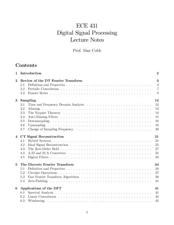
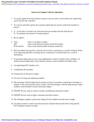
Version 07.00, March 2020Spectral puritySSB phase noisefrequency 1000 MHz, carrier offset100 Hz1 kHz10 kHz100 kHz1 MHz10 MHznom. –88 dBc (1 Hz) –99 dBc (1 Hz) –105 dBc (1 Hz), typ. –108 dBc (1 Hz) –110 dBc (1 Hz), typ. –115 dBc (1 Hz) –130 dBc (1 Hz), typ. –135 dBc (1 Hz)nom. –152 dBc (1 Hz)-60-70SSB phase noise (dBc (1 Hz))-80-90-100 2 MHz100 MHz-1101 GHz3 GHz-1206 GHz-130-140-150-160100 Hz1 kHz10 kHz100 kHz1 MHz10 MHzMeasured phase noise at different center frequenciesSweep timeRangeSweep time accuracyspan 0 Hzspan 10 Hz, RBW 100 kHzspan 10 Hz, RBW 100 kHzspan 0 Hzspan 10 Hz, RBW 100 kHz1 µs to 8000 s1 ms to 8000 s 175 µs to 8000 s 2nom. 0.1 %nom. 3 %sweep filtersFFT filters100 kHz to 10 MHz in 1/2/3/5 sequence1 Hz to 50 kHz in 1/2/3/5 sequencenom. 3 %nom. 5Resolution bandwidthsSweep filters and FFT filtersResolution bandwidths (–3 dB)Bandwidth uncertaintyShape factor 60 dB:3 dB12Net sweep time without additional hardware settling time.Time for data acquisition for FFT calculation.Rohde & Schwarz R&S FPL1000 Signal and Spectrum Analyzer5
Version 07.00, March 2020Channel filtersBandwidths (–3 dB)100/200/300/500 5/14/15/16/20/21/25/30/50/100/150/192/200/300/500 kHz1/1.228/1.5/2/3/3.75/5/10 MHznom. 2 %nom. 2Bandwidth uncertaintyShape factor 60 dB:3 dBEMI filters (with R&S FPL1-K54 option)Bandwidths (–6 dB)10/100/200 Hz1/9/10/100/120 kHz1 MHznom. 3 %nom. 4Bandwidth uncertaintyShape factor 60 dB:6 dBVideo bandwidthsstandard1 Hz to 10 MHz in 1/2/3/5 sequenceSignal analysis bandwidth (equalized)standardwith R&S FPL1-B40 optionnom. 10 MHznom. 40 MHzLevelDisplay rangeMaximum input levelDC voltageCW RF powerPulse spectral densityMaximum pulse voltageMaximum pulse energyIntermodulation1 dB compression of input mixer(two tone)Third-order intercept point (TOI)Second-harmonic intercept (SHI)Displayed average noise level (DANL)RF preamplifier off6displayed noise floor up to 30 dBm50 VRF attenuation 0 dBRF preamplifier offwith R&S FPL1-B22 option,RF preamplifier onRF attenuation 10 dBRF preamplifier offwith R&S FPL1-B22 option,RF preamplifier onRF attenuation 0 dB,RF preamplifier offRF attenuation 10 dBRF attenuation 10 dB, 10 µs20 dBm ( 0.1 W)13 dBm ( 0.02 W)30 dBm ( 1 W)23 dBm ( 0.2 W)97 dB µV/MHz150 V1 mWsRF attenuation 0 dB,nom. 7 dBmRF preamplifier offRF attenuation 0 dB, level 2 –20 dBm, f 5 RBW or 10 kHz, whichever is larger,RF preamplifier off10 MHz fin 300 MHz 13 dBm, typ. 16 dBm300 MHz fin 3 GHz 17 dBm, typ. 20 dBm3 GHz fin 7.5 GHz 15 dBm, typ. 18 dBmwith R&S FPL1-B22 option, RF attenuation 0 dB, level 2 –40 dBm, f 5 RBW or10 kHz, whichever is larger, RF preamplifier on5 MHz fin 7,5 GHznom. 0 dBmRF attenuation 0 dB, level –13 dBm, RF preamplifier off1 MHz fin 900 MHznom. 45 dBm900 MHz fin 3.75 GHznom. 70 dBm0 dB RF attenuation, termination 50 Ω, log. scaling, normalized to 1 Hz RBW,RBW 1 kHz, VBW 1 Hz, sample detector, 20 C to 30 C5 kHz f 100 kHztyp. –143 dBm100 kHz f 5 MHz –140 dBm, typ. –143 dBm5 MHz f 3 GHz –149 dBm, typ. –152 dBm3 GHz f 5 GHz –143 dBm, typ. –146 dBm5 GHz f 7.5 GHz –140 dBm, typ. –143 dBmRohde & Schwarz R&S FPL1000 Signal and Spectrum Analyzer
Version 07.00, March 2020RF preamplifier on(gain nom. 20 dB)Spurious responsesImage responseIntermediate frequency responseResidual spurious responseLocal oscillator related spuriousOther interfering signalsSubharmonic of 1st LOHarmonic of 1st LOLevel displayLogarithmic level axisLinear level axisNumber of tracesTrace detectorTrace functionsEMI detectors (with R&S FPL1-K54)Measurement marker detector(with R&S FPL1-K54)Setting range of reference levelUnits of level axisLevel measurement uncertaintyAbsolute level uncertainty at 50 MHzFrequency responsereferenced to 50 MHz3 MHz f 10 MHz10 MHz f 2 GHz2 GHz f 3 GHz3 GHz f 5 GHz5 GHz f 7 GHz7 GHz f 7.5 GHz –155 dBm, typ. –158 dBm –163 dBm, typ. –166 dBm –162 dBm, typ. –165 dBm –158 dBm, typ. –161 dBm –156 dBm, typ. –159 dBm –155 dBm, typ. –158 dBmmixer level –13 dBm, sweep optimization: auto or dynamic, scaling linear10 MHz f 3 GHzfin – 2 4020.4 MHz (1st IF)typ. –90 dBcfin – 2 820.4 MHz (2nd IF) –80 dBcfin – 2 20.4 MHz (3rd IF), –80 dBcRBW 3 MHz3 GHz f 7.5 GHz,typ. –70 dBcRBW 3 MHz2 MHz f 3 GHz1st IF (4020.4 MHz)typ. –80 dBc2nd IF (820.4 MHz) –80 dBc3rd IF (20.4 MHz) –80 dBc3 GHz f 7.5 GHz –70 dBc0 dB RF attenuationf 1 MHznom. –90 dBmf 1 MHz –90 dBmf 3 GHz1 kHz carrier offset 10 MHz –70 dBccarrier offset 10 MHz –80 dBc3 GHz f 7.5 GHztyp. –70 dBc20 MHz f 3 GHz,spurious at 4020.4 MHz – 2 fin20 MHz f 3 GHz,mixer level –25 dBm,spurious at fin –2010.2 MHznom. –80 dBcnom. –80 dBc1 dB to 200 dB, in 1 dB steps10 % of reference level per level division,10 divisions or logarithmic scaling6max. peak, min. peak, auto peak (normal),sample, RMS, averageclear/write, max. hold, min. hold, average,viewquasi-peak, RMS-average,CISPR-averagemax. peak, average, quasi-peak,RMS-average, CISPR-average–130 dBm to (–13 dBm RF attenuation– RF preamplifier gain),in steps of 0.01 dBdBm, dBµV, dBmV, dBµA, dBpW,V, A, WRBW 10 kHz, level –10 dBm, reference level –10 dBm, RF attenuation 10 dB 20 C to 30 C 0.3 dB (σ 0.1 dB)0 C to 50 C 0.5 dB (σ 0.17 dB)RF attenuation 10/20/30/40 dB, RF preamplifier off, 20 C to 30 C5 kHz f 3 MHznom. 1 dB3 MHz f 3 GHz 0.3 dB (σ 0.1 dB)3 GHz f 7.5 GHz 0.6 dB (σ 0.2 dB)any setting of RF attenuation, RF preamplifier off, 0 C to 50 C5 kHz f 3 GHznom. 1 dB3 GHz f 7.5 GHznom. 1.5 dBRF attenuation 20 dB,RF preamplifier on, 20 C to 30 C3 MHz f 3 GHznom. 0.6 dB3 GHz f 7.5 GHznom. 1 dBRohde & Schwarz R&S FPL1000 Signal and Spectrum Analyzer7
Version 07.00, March 2020 0.2 dB (σ 0.07 dB)Attenuator switching uncertaintyf 50 MHz, 0 dB to 45 dB,referenced to 10 dB attenuationUncertainty of reference level settingBandwidth switching uncertainty0 dB 3referenced to RBW 10 kHz and sweep type FFTsweep type FFT (RBW 100 kHz)nom. 0.1 dBsweep type sweep (RBW 100 kHz) nom. 0.2 dBNonlinearity of displayed levelLogarithmic level displayLinear level displayTotal measurement uncertaintyS/N 16 dB, 0 dB to –50 dBS/N 16 dB, 0 dB to –70 dB 0.1 dB (σ 0.07 dB)nom. 5 % of reference levelsignal level 0 dB to –50 dB below reference level, S/N 20 dB, sweep time auto,sweep type FFT, RF attenuation 10 dB, 20 dB, 30 dB, 40 dB, RF preamplifier off,span/RBW 100, confidence level 95 %, 20 C to 30 C1 MHz f 3 GHz0.5 dB3 GHz f 7.5 GHz0.8 dBMeasurement speedLocal measurement and display updaterateMaximum sweep rate, remote operation 4, 5Remote measurement and LAN transfer 4Marker peak search 4Center frequency tune sweep sweepdata transfer 41001 sweep points, sweep optimizationset to “speed”trace average onnom. 1 ms (1000/s)nom. 0.9 ms (1100/s)nom. 3.2 ms (357/s)nom. 1.9 msnom. 16 msTrigger functionsTriggerTrigger sourceTrigger offsetMaximum deviation of trigger offsetIF power triggerSensitivityspan 10 Hzspan 0 Hzmin. signal powermax. signal powerIF power trigger bandwidthRBW 5 MHzRBW 5 MHzGated sweepGate sourceGate delayGate lengthMaximum deviation of gate lengthfree run, video, external, IF power,I/Q power0 s to 20 s(–sweep time) to 20 s 10 ns–60 dBm RF attenuation –RF preamplifier gain–15 dBm RF attenuation –RF preamplifier gainnom. 40 MHznom. 6 MHzvideo, external, IF power, I/Q power0 s to 20 s, min. resolution 10 ns10 ns to 20 s, min. resolution 10 ns 10 nsI/Q dataInterfaceMemory lengthWord length of I/Q samplesSampling rateMax. signal analysis bandwidth(equalized)3458standardwith R&S FPL1-B40 optionstandardwith R&S FPL1-B40 optionGPIB or LAN interfacemax. 25 Msample I and Q14 bit100 Hz to 16 MHz100 Hz to 100 MHz12.8 MHz40 MHzThe setting of the reference level affects only the graphical representation of the measurement result on the display, not the measurement itself.Therefore, the reference level setting causes no additional uncertainty in measurement results.Measured with a PC equipped with Intel Core i7 2.8 GHz and Gbit LAN interface.Measurement is performed with a sweep count of 1000. The indicated speed is the average speed of 1 sweep.Rohde & Schwarz R&S FPL1000 Signal and Spectrum Analyzer
Version 07.00, March 2020Signal analysis bandwidth 10 MHzAmplitude flatnessDeviation from linear phaseSignal analysis bandwidth 40 MHzAmplitude flatnessDeviation from linear phasefcenter 12 MHz and(1.25 signal analysis bandwidth)fcenter 12 MHz and(1.25 signal analysis bandwidth)nom. 0.3 dBfcenter 12 MHz and(1.25 signal analysis bandwidth)fcenter 12 MHz and(1.25 signal analysis bandwidth)nom. 0.5 dBnom. 1 nom. 1.5 Inputs and outputsRF inputImpedanceConnectorVSWRSetting range of attenuatorRF preamplifier gain50 ΩN femaleRF attenuation 10 dB10 MHz f 3 GHz3 GHz f 7.5 GHzstandardwith R&S FPL1-B25 optionwith R&S FPL1-B22 optionUSB interfaceReference outputConnectorImpedanceOutput frequencynom. 1.5nom. 20 dB to 45 dB, in 5 dB steps0 dB to 45 dB, in 1 dB stepsnom. 20 dB4 ports, type A plug, version 2.0LevelBNC female50 Ω10 MHzsame as reference input signalnom. 0 dBmReference inputConnectorImpedanceInput frequency rangeRequired levelBNC female50 Ω10 MHz 5 ppm 0 dBm into 50 ΩExternal trigger/gate inputConnectorTrigger voltageInput impedanceBNC female0.5 V to 3.5 V10 kΩIEC/IEEE bus controlCommand setConnectorInterface functionsinternal referenceexternal referenceinterface in line with IEC 625-2(IEEE 488.2)SCPI 1997.024-pin Amphenol femaleSH1, AH1, T6, L4, SR1, RL1, PP1, DC1,DT1, C0LAN interfaceConnector10/100/1000BASE-TRJ-45External monitorConnectorDVI-DRohde & Schwarz R&S FPL1000 Signal and Spectrum Analyzer9
Version 07.00, March 2020General dataDisplayResolutionPixel failure rateData storageInternalExternal21 cm LC TFT color display (10.1")1280 800 pixel (WXGA resolution) 1 10–5standardsolid-state drive (SSD) 32 Gbytesupports USB 2.0 compatible memorydevicesClimatic loadingoperating temperature rangestorage temperature rangewithout condensation0 C to 50 C–20 C to 70 C 40 C at 85 % rel. humidity,in line with EN 60068-2-30,Mechanical resistanceVibrationsinusoidal5 Hz to 55 Hz0.15 mm constant amplitude(1.8 g at 55 Hz);55 Hz to 150 Hzacceleration: 0.5 g constant;in line with EN 60068-2-610 Hz to 300 Hz,acceleration 1.2 g (RMS),in line with EN 60068-2-6440 g shock spectrum, in line withMIL-STD-810E method no. 516.4procedure I, MIL-PRF-28800FEnvironmental conditionsTemperaturerandomShockEMCin line with EMC Directive 2014/30/EUincluding IEC/EN 61326-1 6, 7,IEC/EN 61326-2-1, CISPR 11/EN 55011 6,IEC/EN 61000-3-2, IEC/EN 61000-3-3Recommended calibration interval2 yearsPower supplyAC supplywithout battery optionwith battery optionCurrent consumptionwithout optionswith internal battery(option R&S FPL1-B31) in charge modeSafetyin line with EN 61010-1, IEC 61010-1,UL 61010-1, CAN/CSA-C22.2No. 61010-1CSA, CSA-NRTLTest markDimensions and weightDimensionsNet weight, nominal67W H Dwithout optionswith internal batteryEmission limits for class A equipment.Immunity test requirement for industrial environment (EN 61326 table 2).10100 V to 240 V 10 %,50 Hz to 60 Hz 5 %,400 Hz 5 % class of protection I,in line with VDE 411100 V to 240 V 10%,50 Hz to 60 Hz 5%nom. 1.7 A to 0.8 Anom. 3 A to 1.5 ARohde & Schwarz R&S FPL1000 Signal and Spectrum Analyzer408 mm 186 mm 235 mm(16.06 in 7.32 in 9.25 in)6 kg (13.22 lb)7.3 kg (16 lb)
Version 07.00, March 2020OptionsR&S FPL1-B5 additional interfacesUser portConnectorOutputInputNoise source control and power sensorConnectors25-pin D-Sub femaleTTL-compatible, 0 V/5 V, max. 15 mATTL-compatible, max. 5 Vfor R&S FS-SNSxx smart noise sourcesand R&S NRP-Zxx power sensorsfor noise source controlNoise source control output voltageIF/video/demod outConnectorIF outBandwidthIF frequencyOutput levelVideo outBandwidthOutput scalingOutput levelAudio outputLoudspeakerAF outConnectorOutput impedanceOpen-circuit voltage7-pin LEMOSA femaleBNC female0 V/28 V, switchable,max. 100 mA (nom.)BNC female, 50 Ωcenter frequency 10 MHz, span 0 Hz,signal at reference level and centerfrequencylog. display scalelin. display scalecenter frequency 10 MHz, span 0 Hz,signal at reference level and centerfrequencyequal to RBW setting25 MHznom. 0 dBmequal to VBW settinglogarithmiclinearnom. 1 V, open circuitbuilt-in, adjustable3.5 mm mini jack10 Ωup to 1.5 V, adjustableRohde & Schwarz R&S FPL1000 Signal and Spectrum Analyzer11
Version 07.00, March 2020R&S FPL1-B9 internal generatorFrequencyFrequency rangeSetting resolutionR&S FPL1003R&S FPL1007independent CW sourceFrequency offsetSetting rangeSetting resolutionSpectral puritySSB phase noiseHarmonicsNon-harmonic spuriousLevelSpecified level rangeSetting resolutionSetting rangeAbsolute level uncertaintyFrequency responseLevel nonlinearity890 Hz to fmax 80.01 Hzfrequency 1 GHz, output level 0 dBmcarrier offset 10 kHzcarrier offset 100 kHzcarrier offset 1 MHzoutput level 0 dBm5 kHz f 100 kHz100 kHz f 7.5 GHz 9output level 0 dBm1 kHz offset from carrier 4 MHzoffset from carrier 4 MHz –102 dBc (1 Hz), typ. –108 dBc (1 Hz) –105 dBc (1 Hz), typ. –111 dBc (1 Hz) –117 dB (1 Hz), typ. –130 dBc (1 Hz)nom. –30 dBc –30 dBcnom. –35 dBc –35 dBc, typ. –45 dBc–50 dBm to 0 dBm0.1 dB–60 dBm to 10 dBm 0.5 dBfrequency 50 MHz, 20 C to 30 C,output level –10 dBm,frequency offset 0 Hzoutput level –10 dBm, referenced to level at 50 MHz, 20 C to 30 C,frequency offset 0 Hz100 kHz f 3 GHz 1 dB,3 GHz f 7.5 GHz 1.5 dB, typ. 1 dBfor specified level range, referenced to 2 dB, typ. 0.5 dB–10 dBm output level, 20 C to 30 C,f 100 kHzfmax depends on frequency range.Limit is nominal for harmonics at frequencies 20 GHz.125 kHz to 3 GHz5 kHz to 7.5 GHz0.01 HzRohde & Schwarz R&S FPL1000 Signal and Spectrum Analyzer
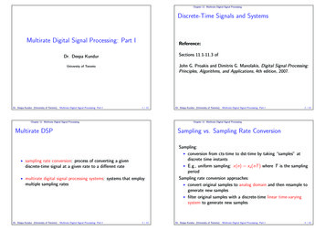
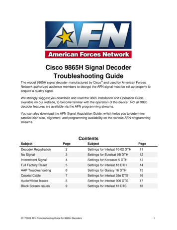
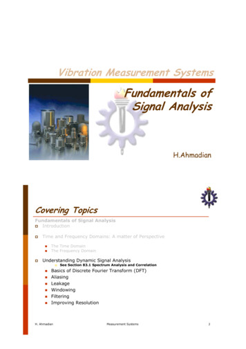
Version 07.00, March 2020Maximum output power versus frequency, level in dBm (meas.).Minimum output power versus frequency, level in dBm (meas.).Dynamic rangeRBW 1 kHz, f 1 GHznom. 115 dBPower sweepSpecified level rangeSetting resolutionSetting range–50 dBm to 0 dBm0.1 dB–60 dBm to 10 dBmGEN outputConnectorVSWRN female, 50 Ωnom. 1.5Reverse powerDC voltageCW RF powerMax. pulse voltageMaximum pulse energy (10 µs)50 V30 dBm ( 1 W)150 V1 mWsRohde & Schwarz R&S FPL1000 Signal and Spectrum Analyzer13
Version 07.00, March 2020R&S FPL1-B30 DC power input 12 V/24 VInput voltage rangeDCInput currentVin 12 V/24 VVin 12 V/24 V, operating mode, withoutinternal batteries (R&S FPL1-B31)Vin 12 V/24 V, operating mode, internalbatteries in charge modeVin 12 V/24 V, instrument standby mode,internal batteries in charge modeoperating temperature rangestorage temperature rangeTemperature12 V to 24 V (nom.),10.4 V to 28 V,switch-on voltage 11 V (meas.)13 A/6.5 A (nom.)5.5 A/2.7 A (meas.)11 A/5 A (meas.)6.5 A/3 A (meas.)0 C to 40 C–20 C to 70 CR&S FPL1-B31 internal lithium-ion batteryOperating timeCharge timeTemperaturestandby mode, AC supplystandby mode, external DC supply(R&S FPL1-B30)operating modeoperating temperature range, dischargeoperating temperature range, chargestorage temperature rangenom. 3.5 hnom. 2 hnom. 2 hnom. 4 h0 C to 50 C0 C to 45 C–20 C to 60 C 10R&S FSV-B34 charger (only needed for charging spare batteries)AC input voltage rangeAC supply frequencyPower consumptionNumber of charger baysDimensionsW H DNet weight10100 V to 240 V, 10 % (nom.)50 Hz to 60 Hz (nom.)max. 300 W (nom.)4400 mm 127 mm 203 mm(15.75 in 5 in 8 in)3.1 kg (6.9 lb)The battery packs should be stored in an environment with low humidity, free from corrosive gas at a recommended temperature range 21 C.Extended exposure to temperatures above 45 C could degrade battery performance and life.14Rohde & Schwarz R&S FPL1000 Signal and Spectrum Analyzer
Version 07.00, March 2020Ordering informationDesignationSignal and spectrum analyzerSignal and spectrum analyzerAccessories suppliedPower cable and quick start guideTypeR&S FPL1003R&S FPL1007Order No.1304.0004.031304.0004.07OptionsDesignationOCXO reference frequencyAdditional interfacesTypeR&S FPL1-B4R&S FPL1-B5Order rnal generatorInternal generatorGPIB interfaceSecond hard disk (SSD)R&S FPL1-B9R&S FPL1-B9R&S FPL1-B10R&S 427.02nonoyesyesRF preamplifier (3 GHz/7.5 GHz)1 dB steps for electronic attenuatorDC power supply 12 V/24 VInternal lithium-ion batteryR&S FPL1-B22R&S FPL1-B25R&S FPL1-B30R&S 725.02yesyesyesyes40 MHz analysis bandwidthFirmwareAM/FM/φM measurement demodulatorPower sensor measurement withR&S NRPxx power sensorsNoise figure and gain measurementsEMI measurement applicationVector signal analysisMulti-modulation analysisBER measurements with PRBS dataSoftwareLicense dongleVector signal explorer base softwareVector signal analysisEUTRA/LTE NB-IoTR&S FPL1-B401323.1931.02yesR&S FPL1-K7R&S FPL1-K91323.1731.021323.1754.02R&S FPL1-K30R&S FPL1-K54R&S FPL1-K70R&S FPL1-K70MR&S 1625.021323.1631.02R&S FSPCR&S VSER&S VSE-K70R&S 900.06Remarksretrofit in service centeruser-retrofittableIF/video/demod out, user port,noise source control, powersensor, AF output, loudspeakerfor R&S FPL1003for R&S FPL1007user-retrofittableuser-retrofittablemounted on PC board,including analyzer etrofittableretrofit in service center;including 2 battery packs andinternal charging unituser-retrofittablesupports R&S NRPxx powersensorsrequires R&S FPL1-B5requires R&S FPL1-K70requires R&S FPL1-K70Recommended extrasDesignationProtective hard coverSoft carrying bag for transport and outdoor operationH-style shoulder harness (requires R&S FPL1-Z2 option)Spare lithium-ion battery packAnti-glare display film for outdoor operationLithium-ion battery charger for charging spare batteries19" rackmount kitHeadphonesUWB antenna module (30 MHz to 6 GHz)Matching pads, 50 Ω/75 ΩL section, matching at both endsSeries resistor, 25 Ω, matching at one end(taken into account in instrument function RF INPUT 75 Ω)Smart noise sourceSmart noise source for noise figure and gain measurements(requires R&S FPL1-K30)High-power attenuatorsAttenuator 100 W, 3/6/10/20/30 dB, 1 GHzTypeR&S FPL1-Z1R&S FPL1-Z2R&S FPL1-Z3R&S FPL1-Z4R&S FPL1-Z5R&S FSV-B34R&S FPL1-Z6R&S HE400UWBOrder 104.6900.02R&S RAMR&S RAZ0358.5414.020358.5714.02R&S FS-SNS261338.8008.26R&S RBU1001073.8495.xx(xx 03/06/10/20/30)Rohde & Schwarz R&S FPL1000 Signal and Spectrum Analyzer15
Version 07.00, March 2020DesignationAttenuator 50 W, 3/6/10/20/30 dB, 2 GHzTypeR&S RBU50Attenuator 50 W, 20 dB, 6 GHzConnectors and cablesIEC/IEEE bus cable, length: 1 mIEC/IEEE bus cable, length: 2 mDC blockDC block, 10 kHz to 18 GHz (type N)R&S RDL50Order No.1073.8695.xx(xx 03/06/10/20/30)1035.1700.52R&S PCKR&S PCK0292.2013.100292.2013.20R&S FSE-Z41084.7443.02Power sensors supported by the R&S FPL1-K9 option 11DesignationUniversal power sensors10 MHz to 8 GHz, 100 mW, two-path10 MHz to 8 GHz, 200 mW 1210 MHz to 18 GHz, 100 mW, two-path10 MHz to 18 GHz, 200 mW 1210 MHz to 18 GHz, 2 W 1210 MHz to 18 GHz, 15 W 1210 MHz to 18 GHz, 30 W 12Power sensor modules with power splitterDC to 18 GHz, 500 mWDC to 26.5 GHz, 500 mWThermal power sensors0 Hz to 18 GHz, 100 mW0 Hz to 18 GHz, 100 mW0 Hz to 33 GHz, 100 mW0 Hz to 33 GHz, 100 mW0 Hz to 40 GHz, 100 mW0 Hz to 40 GHz, 100 mW0 Hz to 50 GHz, 100 mW0 Hz to 50 GHz, 100 mW0 Hz to 67 GHz, 100 mW0 Hz to 67 GHz, 100 mW0 Hz to 110 GHz, 100 mWAverage power sensors8 kHz to 6 GHz, 200 mW8 kHz to 6 GHz, 200 mW9 kHz to 6 GHz, 200 mW 128 kHz to 18 GHz, 200 mW8 kHz to 18 GHz, 200 mWThree-path diode power sensors100 pW to 200 mW, 10 MHz to 8 GHz100 pW to 200 mW, 10 MHz to 8 GHz, LAN version100 pW to 200 mW, 10 MHz to 18 GHz100 pW to 200 mW, 10 MHz to 18 GHz, LAN version1 nW to 2 W, 10 MHz to 18 GHz10 nW to 15 W, 10 MHz to 18 GHz30 nW to 30 W, 10 MHz to 18 GHz100 pW to 200 mW, 10 MHz to 33 GHz100 pW to 200 mW, 10 MHz to 33 GHz, LAN version100 pW to 200 mW, 10 MHz to 33 GHz, LAN version,TVAC-compliant100 pW to 100 mW, 50 MHz to 40 GHz100 pW to 100 mW, 50 MHz to 40 GHz, LAN version100 pW to 100 mW, 50 MHz to 50 GHz100 pW to 100 mW, 50 MHz to 50 GHz, LAN version1112TypeOrder No.R&S NRP-Z211R&S NRP-Z11R&S NRP-Z221R&S NRP-Z21R&S NRP-Z22R&S NRP-Z23R&S 00.021137.7506.021137.8002.021137.8502.02R&S NRP-Z27R&S NRP-Z371169.4102.021169.3206.02R&S NRP18TR&S NRP18TNR&S NRP33TR&S NRP33TNR&S NRP40TR&S NRP40TNR&S NRP50TR&S NRP50TNR&S NRP67TR&S NRP67TNR&S .021424.6196.021424.6209.021424.6215.02R&S NRP6AR&S NRP6ANR&S NRP-Z91R&S NRP18AR&S 15.021424.6821.02R&S NRP8SR&S NRP8SNR&S NRP18SR&S NRP18SNR&S NRP18S-10R&S NRP18S-20R&S NRP18S-25R&S NRP33SR&S NRP33SNR&S 64.021419.0070.021419.0129.02R&S NRP40SR&S NRP40SNR&S NRP50SR&S 93.02For average power measurement only. LAN connection not supported.Product discontinued.16Rohde & Schwarz R&S FPL1000 Signal and Spectrum Analyzer
Version 07.00, March 2020Wideband power se
Bandwidth uncertainty nom. 3 % Shape factor 60 dB:6 dB nom. 4 Video bandwidths standard 1 Hz to 10 MHz in 1/2/3/5 sequence Signal analysis bandwidth (equalized) standard nom. 10 MHz with R&S FPL1-B40 option nom. 40 MHz Level Display range displayed noise floor up to 30 dBm Maximum input level DC voltage 50 V