Transcription
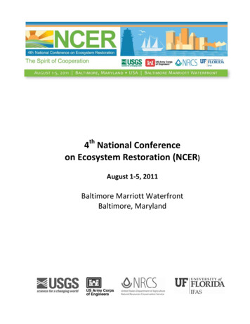
C O A S T A L P R O T E C T I O N A N D R E S T O R AT I O N A U T H O R I T Y2 0 2 2 M A R C H 31Coastal Restoration ProjectGeotechnical Analysis, Design,and Construction2022 COASTAL INDUSTRY WEEKWEBINAR SERIES – SESSION 3A D A M D . L I N S O N , P. E .
CPRA’s Coastal Master PlanCOASTAL PROTECTION AND RESTORATION AUTHORITY / MID-BASIN SEDIMENT DIVERSION PROGRAM2
Overview Marsh Creation Design Guidelines Review of Existing Data Subsurface Investigations- Boring/CPT Layout- Sampling Frequencies and Depths Laboratory Testing- Testing Types and Frequencies Data Synthesis- Subsurface and Parameter Profiles Marsh Creation Settlement Analysis Earthen Containment Dike Design- Slope Stability- Settlement Analysis Construction Monitoring and InstrumentationCOASTAL PROTECTION AND RESTORATION AUTHORITY / MID-BASIN SEDIMENT DIVERSION PROGRAM3
Marsh Creation Design Guidelines Created in November 2017 to serve as the minimum design standard consistent for the design andconstruction of marsh creation projects within the Louisiana Coastal Zone.- NOT intended to replace professional engineering judgement of the design engineer. The Marsh Creation Design Guidelines (MCDG) provide an overview of subsurface investigations (Section3.5.3), geotechnical engineering of marsh creation projects (3.5.4), and overall marsh creation design (3.6). Appendix B of the MCDG contains the Geotechnical Standards for Marsh Creation and Coastal RestorationProjects, intended to be used as minimal standards for marsh creation projects, and includes guidance for:- Subsurface Investigations- Laboratory Testing Requirements- Earthen Containment Dike Geometry and Slope Stability Design- Estimated Consolidation Settlement Design Requirements The MCDG an appendices contain information on the topics discussed in this d-design-standards/COASTAL PROTECTION AND RESTORATION AUTHORITY / MID-BASIN SEDIMENT DIVERSION PROGRAM4
Review of Existing DataSOURCES AND IMPACTS TO SUBSURFACE INVESTIGATIONS A review of existing data can influence the scope of work and scheduling requirements of asubsurface investigation, as well as laboratory testing needs. More specifically, existing datasources can influence items such as:- Assessing equipment needs and/or access requirements;- Depth, frequency, and layout of borings and cone penetrometer tests (CPTs), and;- Determination of sampling locations for a potential borrow source or other project features. Existing data sources may include, but are not limited to:- Geologic and geomorphic maps;- Aerial imagery;- Existing borings logs and CPTs;- Published papers and reports, and;- Information from local, state, and federal agencies.COASTAL PROTECTION AND RESTORATION AUTHORITY / MID-BASIN SEDIMENT DIVERSION PROGRAM5
Review of Existing DataCOASTAL INFORMATION MANAGEMENT SYSTEM (CIMS) Link: https://cims.coastal.la.gov/MapHome.aspx Main Spatial Viewer – full featured GIS for CPRA projects, monitoring data, restoration and projectfeatures, geotechnical data, and geophysical information.COASTAL PROTECTION AND RESTORATION AUTHORITY / MID-BASIN SEDIMENT DIVERSION PROGRAM6
CPRAMID-BASIN SEDIMENT DIVERSION PROGRAMSubsurfaceInvestigations &Laboratory Testing7
Subsurface InvestigationsSAMPLING T YPE, DEPTH, AND FREQUENCY/SPACINGSAMPLING T YPE (BORINGS VS. CPTS) Cone Penetrometer Tests (CPTs):- Allows for continuous soil profiling at an increased production rate.- Does not provide physical soil samples.- Penetration depth limited in very dense sands/gravels or stiff clays.- Poor resolution in highly sensitive materials (i.e. organic clays or peats). Soil Borings:- Profiling is often not continuous beyond 20 feet.- Provides physical soil samples for laboratory testing.- Allows for classification of highly-sensitive materials and very dense sands/gravels or stiff clays.SAMPLING DEPTH Dependent on specific project feature and required analysis (slope stability, settlement analysis, etc.)F R E Q U E N C Y / S PAC I N G Also feature-dependent, but can also be dependent on variability in subsurface materials.COASTAL PROTECTION AND RESTORATION AUTHORITY / MID-BASIN SEDIMENT DIVERSION PROGRAM8
Subsurface InvestigationsSPACING AND DEPTH BY PROJECT FEATURECOASTAL PROTECTION AND RESTORATION AUTHORITY / MID-BASIN SEDIMENT DIVERSION PROGRAM9
Subsurface InvestigationsEXAMPLE SUBSURFACE INVESTIGATION Marsh Creation Areas (MCAs):- 2 in each MCA (1 per 90 acres)- 40-ft depth Earthen Containment Dikes (ECDs):- 7 CPTs & 3 co-located borings (1 per 2,700 LF)- 40-ft depth Earthen Ridge:- 6 CPTs & 3 co-located borings (1 per 1,800 LF)- 50-ft depth Terrace Fields:- 2 borings & 3 CPTs (1 per 70 acres)- 40-ft depth Earthen Ridge Borrow:- 3 borings- 20-ft depthCOASTAL PROTECTION AND RESTORATION AUTHORITY / MID-BASIN SEDIMENT DIVERSION PROGRAM10
Subsurface InvestigationsEXAMPLE PERMITTING LAYOUT 49 permitting locations narroweddown to 28 locations for finalscope. Over-permitting allows foradditional CPTs/borings to beperformed in the future, if needed. Denoting locations as both boringsand CPTs provides flexibility inplanning.COASTAL PROTECTION AND RESTORATION AUTHORITY / MID-BASIN SEDIMENT DIVERSION PROGRAM11
Subsurface InvestigationsOTHER CONSIDERATIONS Subsurface investigations can be performed in a phased approach. A few CPTs should be co-located with borings to provide a site-specific cone factor necessary tobetter process CPT data. Additional investigations may be necessary due to factors such as geologic variability, weak orcompressible soils, need for reduced spacing, or by engineering judgement. Over-permitting allows for flexibility in performing additional borings/CPTs in the future, shouldthe need arise, without the need for a permit modification.COASTAL PROTECTION AND RESTORATION AUTHORITY / MID-BASIN SEDIMENT DIVERSION PROGRAM12
Laboratory TestingTESTING T YPES AND IMPORTANCE IN DESIGNCategoryTest NameMoisture ContentAtterberg LimitsClassificationTestsParticle-Size DistributionOrganic ContentUnit WeightStrengthTestingConsolidationUse in Analysis/DesignTo help define subsurface stratigraphy, use inestablished correlations to other properties,estimate soil behaviors during construction, andmore.A key input parameter for settlement and slopestability analyses.Unconsolidated Undrained (UU) For use in slope stability analysis of earthencontainment dikes, earthen ridges, and otherUnconfined Compression (UC) earthen features.Consolidation TestingFor use in estimating magnitude and time-ratesettlement of foundation soilsSettling ColumnDredge SlurryFor use in estimating magnitude and time rateTestingLow Stress Consolidation Testing settlement of dredged materials.COASTAL PROTECTION AND RESTORATION AUTHORITY / MID-BASIN SEDIMENT DIVERSION PROGRAM13
CPRAMID-BASIN SEDIMENT DIVERSION PROGRAMData Synthesis andInterpretation14
Data Synthesis and InterpretationBORING LOG DEVELOPMENTHigh moisture contentLow shear strengthCOASTAL PROTECTION AND RESTORATION AUTHORITY / MID-BASIN SEDIMENT DIVERSION PROGRAMBoring Log Credit: GeoEngineers15
Data Synthesis and InterpretationCPT LOG DEVELOPMENTLow shear strengthDifficult determiningSBT in highly-sensitivematerialsCOASTAL PROTECTION AND RESTORATION AUTHORITY / MID-BASIN SEDIMENT DIVERSION PROGRAM16
Data Synthesis and InterpretationDEFINING SUBSURFACE AND PARAMETER PROFILES After completion of the subsurface investigation, laboratory testing, and development of the boring/CPT logs,subsurface stratigraphy profiles are often generated next. Depending on the subsurface stratigraphy of the project area, multiple profiles or “reaches” may be necessary to definethe entire site. While reaches are commonly defined on the basis of subsurface soil stratigraphy, they can also be defined based on theresults of the laboratory testing (i.e. consolidation parameters, shear strength, moisture content, etc.). In addition to plotting subsurface soil stratigraphy, the following soil parameters profiles are also generated to beutilized in geotechnical analysis and design:- Moisture content- Shear strength- Unit weight- Consolidation parametersCOASTAL PROTECTION AND RESTORATION AUTHORITY / MID-BASIN SEDIMENT DIVERSION PROGRAM17
Data Synthesis and InterpretationSUBSURFACE SOIL STRATIGRAPHY EXAMPLE In the example shown, theproject area was divided intothree reaches, based on soilsubsurface stratigraphy:- A-A’- B-B’- C-C’ Settlement and stabilityparameters were alsogenerated for these reaches.COASTAL PROTECTION AND RESTORATION AUTHORITY / MID-BASIN SEDIMENT DIVERSION PROGRAM18
Data Synthesis and InterpretationSUBSURFACE SOIL STRATIGRAPHY EXAMPLE This figure shows the soil stratigraphy for cross sections A-A’ and B-B’ from the plan view on the previous slide.COASTAL PROTECTION AND RESTORATION AUTHORITY / MID-BASIN SEDIMENT DIVERSION PROGRAM19
Data Synthesis and InterpretationSUBSURFACE SOIL STRATIGRAPHY EXAMPLE Soil stratigraphy for cross sections C-C’ (Slide 17). The stratigraphy of C-C’ is similar to A-A’, but soil parameters vary.COASTAL PROTECTION AND RESTORATION AUTHORITY / MID-BASIN SEDIMENT DIVERSION PROGRAM20
Data Synthesis and InterpretationSHEAR STRENGTH / UNIT WEIGHT DESIGN PROFILE EXAMPLE100-150 psfshear strengthin upper 5 to 10feet This figure shows the moisture content, shear strength, and unit weigh profiles developed for profile A-A’ using labtesting data as well as CPT data. Shear strength and unit weight are the primary drivers of stability analyses.COASTAL PROTECTION AND RESTORATION AUTHORITY / MID-BASIN SEDIMENT DIVERSION PROGRAM21
Data Synthesis and InterpretationSHEAR STRENGTH / UNIT WEIGHT DESIGN PROFILE EXAMPLE30-75 psf shearstrength inupper 5 to 10feet This figure shows the moisture content, shear strength, and unit weigh profiles developed for profile B-B’ using labtesting data as well as CPT data. Shear strength and unit weight are the primary drivers of stability analyses.COASTAL PROTECTION AND RESTORATION AUTHORITY / MID-BASIN SEDIMENT DIVERSION PROGRAM22
Data Synthesis and InterpretationSHEAR STRENGTH / UNIT WEIGHT DESIGN PROFILE EXAMPLE70-150 psfshear strengthin upper 5 to 10feet This figure shows the moisture content, shear strength, and unit weigh profiles developed for profile B-B’ using labtesting data as well as CPT data. Shear strength and unit weight are the primary drivers of stability analyses.COASTAL PROTECTION AND RESTORATION AUTHORITY / MID-BASIN SEDIMENT DIVERSION PROGRAM23
Data Synthesis and InterpretationCONSOLIDATION DESIGN PROFILE EXAMPLECOASTAL PROTECTION AND RESTORATION AUTHORITY / MID-BASIN SEDIMENT DIVERSION PROGRAM24
CPRAMID-BASIN SEDIMENT DIVERSION PROGRAMMarsh CreationSettlement Analysis25
Marsh Creation Settlement AnalysisGENERAL PROCEDURE FOR ANALYSIS1. Define existing site conditions, such as:- Hydrologic conditions (MHW, MLW, sea level rise, inundation range)- Subsidence rate (and accretion rate, if data is available)- Existing topography (mudline distribution)- Rainfall and evaporation rate data for the project area (NWS34) (for PSDDF)2. Select an analysis program (influences the geotechnical parameters to be defined)- PSDDF, Settle3, etc.3. Define site-specific geotechnical parameters for analysis:- Index properties (moisture content, unit weight)- Consolidation properties of dredge slurry and foundation soils4. Estimate properties relating to dredge fill operations, such as:- Dredge production rate / fill period of MCAs- Slurry concentration (upper bound and lower bound)COASTAL PROTECTION AND RESTORATION AUTHORITY / MID-BASIN SEDIMENT DIVERSION PROGRAM26
Marsh Creation Settlement AnalysisGENERAL PROCEDURE FOR ANALYSIS5. Establish the lower-bound target for marsh elevation at target year 20 (TY20).- Typically taken as the lower bound of the inundation range at TY20.6. Perform settlement analysis using selected geotechnical software, aiming for the lower-bound target elevation andusing the worst cast settlement parameters: upper-bound concentration and lower-bound mudline.7. Determine the constructed marsh fill elevation (CMFE) for this TY20 elevation.8. Increase the CMFE determined in Step 6 to provide a construction tolerance and determine the TY20 elevation.9. Repeat for upper-bound mudline or additional mudlines of interest.10. Repeat for selected lower-bound concentration.11. Perform analyses for other settlement profiles, if applicable.COASTAL PROTECTION AND RESTORATION AUTHORITY / MID-BASIN SEDIMENT DIVERSION PROGRAM27
Marsh Creation Settlement AnalysisDEFINING EXISTING SITE CONDITIONS – HYDROLOGIC Hourly hydrologic data (MHW, MLW, MTL) is typically obtained from a nearby CRMS station for the most recent 5-yearperiod. CRMS stations located near a project area can be found using the Coastwide Reference Monitoring System (CRMS)Database:https://www.lacoast.gov/crms viewer/Map/CRMSViewerCOASTAL PROTECTION AND RESTORATION AUTHORITY / MID-BASIN SEDIMENT DIVERSION PROGRAM28
Marsh Creation Settlement AnalysisDEFINING EXISTING SITE CONDITIONS – HYDROLOGIC Once a CRMS station has been located, the CIMS database can be used to retrieve the hourly hydrologic data:https://cims.coastal.la.gov/monitoring-data/ Sea Level Rise is calculated by CPRA’s Planning Division, generally using a 1.0 meter by 2100 scenario (eustatic).COASTAL PROTECTION AND RESTORATION AUTHORITY / MID-BASIN SEDIMENT DIVERSION PROGRAM29
Marsh Creation Settlement AnalysisDEFINING EXISTING SITE CONDITIONS - HYDROLOGIC Percent Inundation Method is used to establish the optimal inundation range of the marsh, based on information fromSnedden & Swenson 2012. Percentiles are calculated based on the collected CIMS hydrologic data and CRMS estimates of marsh type.COASTAL PROTECTION AND RESTORATION AUTHORITY / MID-BASIN SEDIMENT DIVERSION PROGRAM30
Marsh Creation Settlement AnalysisDEFINING EXISTING SITE CONDITIONS – HYDROLOGIC “Optimal” refers to theproductivity of the marsh basedon salinity and vertical positionof the marsh in relation to waterlevels. This range generally provides alarger area to work with whengenerating settlement curvesversus designing to remainwithin MHW and MLW.2.50Elevation (FT, NAVD88 - Geoid 12B) Previous example showed an“intermediate” marsh typewhich correlates to an optimalinundation range of 10% to 90%inundated. 2.07 ft.2.001.501.000.50 0.66 ft.0.0002MHW ESLR (ft)COASTAL PROTECTION AND RESTORATION AUTHORITY / MID-BASIN SEDIMENT DIVERSION PROGRAM46810Year1214MLW ESLR (ft)10% ESLR (ft)Marsh TypeOptimalInundation %Saline20%-80%16182090% ESLR (ft)31
Marsh Creation Settlement AnalysisDEFINING EXISTING SITE CONDITIONS – SOILS Subsidence rate (and accretion rate,if data is available)- Accretion rate data is less readilyavailable. Assumptions onaccretion rates are generally madeon a project-by-project basis ifnearby data is available. Existing topography (mudlinedistribution)Avg. Elevation -1.22 ft (NAVD88, Geoid12B) 1.0 and aboveMudline Elevation Range (ft., NAVD88 Geoid12B)- Subsidence rates have beenestablished by CPRA’s Planningdivision, on a per basin basis.Example, Pontchartrain basinsubsidence is estimated to beapproximately 5.1 mm/year (0.2inches/year).MCA-1 Mudline Elevation Distribution 0.5' to 1.0'0.0' to 0.5'-0.5' to 0.0'-1.0' to -0.5'-1.5' to -1.0'-2.0' to -1.5'-2.5' to -2.0'-3.0' to -2.5'-3.0' and belowCOASTAL PROTECTION AND RESTORATION AUTHORITY / MID-BASIN SEDIMENT DIVERSION PROGRAM0.0%5.0%10.0%15.0%20.0%Analyze mudline at -1.0’ and -2.0’25.0%30.0%32
Marsh Creation Settlement AnalysisSELECTING AN ANALYSIS PROGRAMPRIMARY CONS OLIDAT I ON , S ECONDA RY COMPRES S I ON , AND DES IC C AT ION OF DRE D G EFILL ( PS DDF) Commonly used for projects with mixed sediment borrow sources to analyze settlement of dredged slurry. Can also be used to analyze foundation settlement. Can be used in conjunction with other foundation settlement programs, such as Settle3, to generatesettlement curves.S E T T L E 3 ( RO C S C I E N C E ) Commonly used for project with granular (sand) borrow sources. Can be also used to analyze foundation settlement for mixed sediment borrow projects, but still requires theuse of PSDDF for slurry settlement.COASTAL PROTECTION AND RESTORATION AUTHORITY / MID-BASIN SEDIMENT DIVERSION PROGRAM33
Marsh Creation Settlement AnalysisDEFINING SITE-SPECIFIC GEOTECHNICAL CONDITIONS (PSDDF)C O N S O L I DAT I O N P RO P E R T I E S O F D R E D G E S LU R RY Specific Gravity of Soil Solids, SG Secondary Compression Index / Coefficient of Consolidation, C α/C c Recompression Index / Compression Index, C r/C c Effective Stress (σ’) – Void Ratio (e) – Permeability (k) RelationshipColumnSettling & LowStressConsolidationTesting Desiccation Limit, DL Saturation Limit, SL Depth to Second Stage Drying Degree of Saturation at Desiccation LimitDesiccationParameters(PSDDFManual)C O N S O L I D AT I O N P R O P E R T I E S O F M A R S H C R E AT I O N A R E A ( F O U N D AT I O N ) S O I L S Specific Gravity of Soil Solids (SG) Secondary Compression Index / Coefficient of Consolidation, C α/C c Recompression Index / Compression Index, C r/C c Effective Stress (σ’) – Void Ratio (e) – Permeability (k) RelationshipCOASTAL PROTECTION AND RESTORATION AUTHORITY / MID-BASIN SEDIMENT DIVERSION PROGRAM1-DConsolidationTesting34
Marsh Creation Settlement AnalysisDEFINING SITE-SPECIFIC GEOTECHNICAL CONDITIONS (SETTLE3)C O N S O L I D AT I O N P R O P E R T I E S O F M A R S H C R E AT I O N A R E A ( F O U N D AT I O N ) S O I L S Moisture Content, MC Specific Gravity, SG Cohesion, C Unit Weight, γUU or UC Test Void Ratio, e0 Compression Index, C c Secondary Compression Index / Coefficient of Consolidation, C α/C c Recompression Index, C r Coefficient of Consolidation, C v1-DConsolidationTesting Preconsolidation Pressure, P’ c Overburden Pressure, σ’ v Overconsolidation Ratio, OCR*PSDDF is still necessary to compute consolidation of mixed sediment dredge slurry.COASTAL PROTECTION AND RESTORATION AUTHORITY / MID-BASIN SEDIMENT DIVERSION PROGRAM35
Marsh Creation Settlement AnalysisDREDGING OPERATION ASSUMPTIONS Generate lift schedule- Dependent on dredge size (production rate)and marsh creation area size- Past project data or USACE production ratescan be used Establish slurry concentrations for analysis- Upper Bound Concentration ( 300 g/L): usedto estimate benefits and analyze worst-casescenario settlement conditions- Lower Bound Concentration ( 150 g/L): usedto determined maximum potential slurryelevation that influences the selection of theECD crown elevationCOASTAL PROTECTION AND RESTORATION AUTHORITY / MID-BASIN SEDIMENT DIVERSION PROGRAM36
Marsh Creation Settlement AnalysisPRIMARY CONSOLIDATION, SECONDARY COMPRESSION, AND DESICCATIONOF DREDGE FILL (PSDDF)COASTAL PROTECTION AND RESTORATION AUTHORITY / MID-BASIN SEDIMENT DIVERSION PROGRAM37
Marsh Creation Settlement AnalysisEXAMPLE SETTLEMENT ANALYSIS3. Increase CMFE to createconstruction tolerance4. Determine TY20elevation at upper CMFE.5. Repeat for upper-bound orsecondary mudline.1. Analysis atlower boundmudline atupper boundconcentration2. Establish CMFE at lowerbound mudline and upperbound concentrationCOASTAL PROTECTION AND RESTORATION AUTHORITY / MID-BASIN SEDIMENT DIVERSION PROGRAM38
Marsh Creation Settlement AnalysisEXAMPLE SETTLEMENT ANALYSIS6. Repeat analysis forlower-boundconcentration, attemptingto match TY20 elevationto determine maximumCMFE.COASTAL PROTECTION AND RESTORATION AUTHORITY / MID-BASIN SEDIMENT DIVERSION PROGRAM39
Marsh Creation Settlement AnalysisEXAMPLE SETTLEMENT ANALYSISEstimate CMFE at 150 g/L in attempt tomatch TY20 max elevationSettlement analysis tocompute TY20 elevation. IfTY20 elevation at 150 g/Ldoes not closely match TY20elevation at 300 g/L, selectnew CMFE. Iterate as needed.Determine Max TY20 Elevationfrom the “Swath”COASTAL PROTECTION AND RESTORATION AUTHORITY / MID-BASIN SEDIMENT DIVERSION PROGRAM40
Marsh Creation Settlement AnalysisEXAMPLE SETTLEMENT ANALYSISCOASTAL PROTECTION AND RESTORATION AUTHORITY / MID-BASIN SEDIMENT DIVERSION PROGRAM41
Marsh Creation Settlement AnalysisA DYNAMIC PROCESS A slight deviation in expectedsoil characteristics or assumedconstruction conditions orpractices will likely require are-analysis of settlement. Construction monitoring isimportant to makeadjustments on the fly. It is critical for the designengineer to be incommunication with thegeotechnical consultant.COASTAL PROTECTION AND RESTORATION AUTHORITY / MID-BASIN SEDIMENT DIVERSION PROGRAM42
CPRAMID-BASIN SEDIMENT DIVERSION PROGRAMEarthen ContainmentDike Design43
Earthen Containment Dike DesignGENERAL PROCEDURE FOR ANALYSIS1. Define existing site conditions, such as:- Hydrologic conditions (MHW, MLW)- Subsidence rate (and accretion rate, if data is available)- Existing topography (mudline distribution)2. Select an analysis program for:- Slope Stability Analysis: Slope/W, Slide, etc.- Settlement Analysis: Settle3, CSETT, etc.3. Define site-specific geotechnical parameters for analysis:- Strength and unit weight trends of foundation soils and ECD fill materials (slope stability)- Drainage boundary conditions (slope stability)- Consolidation properties of foundation soils and ECD fill materials (settlement analysis)COASTAL PROTECTION AND RESTORATION AUTHORITY / MID-BASIN SEDIMENT DIVERSION PROGRAM44
Earthen Containment Dike DesignGENERAL PROCEDURE FOR ANALYSIS4. From the results of the marsh creation area settlement analysis, determine the maximum crown elevation.- 1-2 feet of freeboard above the upper-bound CMFE at 300 g/L design curve or- 1-foot of freeboard above the upper-bound CMFE at 150 g/L design curve (Lower concentration higherCMFE the need for a higher ECD)5. Perform slope stability analysis to determine an ECD section meeting the minimum F.S. requirementsestablished in CPRA’s Marsh Creation Design Guidelines, v1 (MCDGv1.0).- Evaluate for multiple mudlines, based on the mudline distribution.- Evaluate for multiple soil profiles, as needed.6. Perform settlement analysis for established ECD sections and selected mudline elevations.COASTAL PROTECTION AND RESTORATION AUTHORITY / MID-BASIN SEDIMENT DIVERSION PROGRAM45
Earthen Containment Dike DesignDEFINING EXISTING SITE CONDITIONS Subsidence rate (and accretion rate, if data is available)- Subsidence rates have been established by CPRA’sPlanning division, on a per basin basis. Example,Pontchartrain basin subsidence is estimated to beapproximately 5.1 mm/year (0.2 inches/year).- Accretion rate data is less readily available.Assumptions on accretion rates are generally madeon a project-by-project basis if nearby data isavailable.MCA-1 Mudline Elevation DistributionAvg. Elevation -1.22 ft (NAVD88, Geoid12B)Mudline Elevation Range (ft., NAVD88 Geoid12B) Hydrologic data (MHW, MLW, MTL) is typically obtainedfrom a nearby CRMS station for the most recent 5-yearperiod. 1.0 and above 0.5' to 1.0'0.0' to 0.5'-0.5' to 0.0'-1.0' to -0.5'-1.5' to -1.0'-2.0' to -1.5'-2.5' to -2.0'-3.0' to -2.5'-3.0' and below0.0%5.0%10.0%15.0%20.0%25.0%30.0%Analyze mudline at -1.0’ and -2.0’ Existing topography (mudline distribution)COASTAL PROTECTION AND RESTORATION AUTHORITY / MID-BASIN SEDIMENT DIVERSION PROGRAM46
Earthen Containment Dike DesignDEFINING SITE-SPECIFIC GEOTECHNICAL PARAMETERS – SLOPE STABILIT YCOASTAL PROTECTION AND RESTORATION AUTHORITY / MID-BASIN SEDIMENT DIVERSION PROGRAM47
Earthen Containment Dike DesignDEFINING SITE-SPECIFIC GEOTECHNICAL PARAMETERS – SLOPE STABILIT Y60-70 psf shearstrengths inprevious example.Excavated materialstrength may belower.COASTAL PROTECTION AND RESTORATION AUTHORITY / MID-BASIN SEDIMENT DIVERSION PROGRAM48
Earthen Containment Dike DesignDEFINING SITE-SPECIFIC GEOTECHNICAL PARAMETERS – SETTLEMENTCOASTAL PROTECTION AND RESTORATION AUTHORITY / MID-BASIN SEDIMENT DIVERSION PROGRAM49
Earthen Containment Dike DesignUTILIZING MARSH CREATION AREA SETTLEMENT ANALYSIS RESULTSCOASTAL PROTECTION AND RESTORATION AUTHORITY / MID-BASIN SEDIMENT DIVERSION PROGRAM50
Earthen Containment Dike DesignSLOPE STABILIT Y ANALYSIS CASESMaximum Scenario: set at 1-ftabove maximum CMFECOASTAL PROTECTION AND RESTORATION AUTHORITY / MID-BASIN SEDIMENT DIVERSION PROGRAMWorst Case Scenario: set atmaximum elevation determinedfrom MCA settlement analysis(lower concentration, lowermudline)51
Earthen Containment Dike DesignSLOPE STABILIT Y ANALYSISC A S E A - 1 : G L O B A L S TA B I L I T Y C H E C K ; D U R I N G E C D B O R R O W E X C AVAT I O N ( FA I L U R E W I T H I N T H E E C D )COASTAL PROTECTION AND RESTORATION AUTHORITY / MID-BASIN SEDIMENT DIVERSION PROGRAM52
Earthen Containment Dike DesignSLOPE STABILIT Y ANALYSISC A S E A - 1 : G L O B A L S TA B I L I T Y C H E C K ; D U R I N G E C D B O R R O W E X C AVAT I O N ( FA I L U R E W I T H R E S P E C T TOTHE BORROW PIT)COASTAL PROTECTION AND RESTORATION AUTHORITY / MID-BASIN SEDIMENT DIVERSION PROGRAM53
Earthen Containment Dike DesignSLOPE STABILIT Y ANALYSISC A S E A - 2 : L O C A L S TA B I L I T Y C H E C K ; D U R I N G E C D B O R R O W E X C AVAT I O N ; D I S T R I B U T E D L O A D F R O ME X C AVAT I O N E Q U I P M E N TCOASTAL PROTECTION AND RESTORATION AUTHORITY / MID-BASIN SEDIMENT DIVERSION PROGRAM54
Earthen Containment Dike DesignSLOPE STABILIT Y ANALYSISC A S E B : D R E D G E M AT E R I A L P L AC E D TO C M F E ( M A X I M U M )COASTAL PROTECTION AND RESTORATION AUTHORITY / MID-BASIN SEDIMENT DIVERSION PROGRAM55
Earthen Containment Dike DesignCONSIDERATIONS FOR SLOPE STABILIT Y ANALYSIS There are multiple ways to model construction equipment for the settlement analysis- Continuous strip load (more conservative) vs. two separate strip loads to model equipment tracks- Accounting for buoyancy It is generally preferred to build ECDs larger than to include geotextile fabrics:- Installation of fabric is difficult.- Increases overall cost of the project.- Creates O&M concerns. Hay bales and/or sheet pile design may be necessary depending on geotechnical conditions and mudline elevations. Accounting for potential mud-waving of surficial organic layers can be analyzed in multiple ways:- Assume material is displaced, and the existing mudline is now deeper.- Include in stability analysis and estimate geotechnical properties. Shear strength gain between lifts can help increase factors of safety.COASTAL PROTECTION AND RESTORATION AUTHORITY / MID-BASIN SEDIMENT DIVERSION PROGRAM56
Earthen Containment Dike DesignSETTLEMENT ANALYSIS RESULTSCOASTAL PROTECTION AND RESTORATION AUTHORITY / MID-BASIN SEDIMENT DIVERSION PROGRAM57
Earthen Containment Dike DesignTAKEAWAYS A slight deviation in expected soilcharacteristics or assumedconstruction conditions or practiceswill likely require a re-analysis. Marsh creation and earthencontainment design feed into eachother. Modeling the mudwave is difficult. Construction monitoring is important tomake adjustments on the fly. It is critical for the design engineer tobe in communication with thegeotechnical consultant.COASTAL PROTECTION AND RESTORATION AUTHORITY / MID-BASIN SEDIMENT DIVERSION PROGRAMFigure Credit: GeoEngineers58
CPRAMID-BASIN SEDIMENT DIVERSION PROGRAMConstruction Geotech59
Construction PracticesAPPLYING TO CHANGING CONDITIONS Field sampling of dredge slurry allows for settlement curve adjustments during construction. Sampling of the constructed ECD may be necessary to make adjustments to slope stability orsettlement analyses should issues arise. Instrumented settlement plates provide insight into effective and total stresses present duringdredging operations that can be used to evaluate the project during construction. Piezometers can be used to monitor pore pressure dissipation and inform earthen containmentdike lift schedules. Settlement plate data can be used to gain insight on potential future projects in the vicinity.COASTAL PROTECTION AND RESTORATION AUTHORITY / MID-BASIN SEDIMENT DIVERSION PROGRAM60
Construction PracticesADAPTING TO CHANGING CONDITIONS – INSTRUMENTED SETTLEMENTPLATES (ISP)PiezometerData LoggerCOASTAL PROTECTION AND RESTORATION AUTHORITY / MID-BASIN SEDIMENT DIVERSION PROGRAMPressure Cell61
Construction PracticesADAPTING TO CHANGING CONDITIONS – INSTRUMENTED SETTLEMENTPLATES (ISP)DredgingPost-DredgingSolids pressurecan be used todetermine ifenough soil solidshave been placedto meet projectgoalsCOASTAL PROTECTION AND RESTORATION AUTHORITY / MID-BASIN SEDIMENT DIVERSION PROGRAM62
Conclusions and TakeawaysGEOTECHNICAL DESIGN OF MARSH CREATION PROJECTS Soft soils on marsh creation projects are softer than you may think.- Shear strength values less than 100-150 psf are very common in the upper 10-15 feet of marsh creation project.- A majority of projects contain surficial peat and organic clay layers that make design and construction challenging. Marsh creation settlement (and even containment design) is a dynamic process.- A large number of assumptions have to be made in order to generate estimates of settlement.- A slight deviation in expected soil characteristics or assumptions may require a re-analysis of settlement. Earthen containment and marsh creation design feed into each other. The analyses inform each other. Data collection and analysis during construction allow for adjustments on the fly.- ISP data can help make informed decisions on marsh elevation and quantities in real time.- Field sampling of slurry or ECD materials can be used to make adjustments to design analyses. It is critical for the design engineer to remain in communication with the geotechnical consultant.COASTAL PROTECTION AND RESTORATION AUTHORITY / MID-BASIN SEDIMENT DIVERSION PROGRAM6
coastal protection and restoration authority / mid-basin sediment diversion program 8 sampling type (borings vs. cpts) cone penetrometer tests (cpts):