Transcription
ADM X3 Mobile Bearing Hip SystemSurgical ProtocolAvailable with X3 AdvancedBearing TechnologyFor Use With Restoration ADMCups and Inserts
ADM X3Mobile Bearing Hip SystemSurgical ProtocolWarnings and Precautions . . . . . . . . . . . . . . . . . . . . . . . . . . . . . . . . . . . . . . . . . . . . . . . 1Introduction . . . . . . . . . . . . . . . . . . . . . . . . . . . . . . . . . . . . . . . . . . . . . . . . . . . . . . . . . . . 2Step 1 . . . . . . . . . . . . . . . . . . . . . . . . . . . . . . . . . . . . . . . . . . . . . . . . . . . . . . . . . . . . . . . . . 4Pre-operative Planning and X-ray Evaluation . . . . . . . . . . . . . . . . . . . . . . . . . . . . . . . .4Step 2 . . . . . . . . . . . . . . . . . . . . . . . . . . . . . . . . . . . . . . . . . . . . . . . . . . . . . . . . . . . . . . . . . 4Acetabular Preparation . . . . . . . . . . . . . . . . . . . . . . . . . . . . . . . . . . . . . . . . . . . . . . . . . . .4Step 3 . . . . . . . . . . . . . . . . . . . . . . . . . . . . . . . . . . . . . . . . . . . . . . . . . . . . . . . . . . . . . . . . . 4Spherical Reaming . . . . . . . . . . . . . . . . . . . . . . . . . . . . . . . . . . . . . . . . . . . . . . . . . . . . . . .4Step 4 . . . . . . . . . . . . . . . . . . . . . . . . . . . . . . . . . . . . . . . . . . . . . . . . . . . . . . . . . . . . . . . . . 6Trial Evaluation of the Restoration ADM Cup . . . . . . . . . . . . . . . . . . . . . . . . . . . . . . . .6Step 5 . . . . . . . . . . . . . . . . . . . . . . . . . . . . . . . . . . . . . . . . . . . . . . . . . . . . . . . . . . . . . . . . . 7Restoration ADM Cup Implantation . . . . . . . . . . . . . . . . . . . . . . . . . . . . . . . . . . . . . . . .7Step 6 . . . . . . . . . . . . . . . . . . . . . . . . . . . . . . . . . . . . . . . . . . . . . . . . . . . . . . . . . . . . . . . . . .9Insert/Head Trial Reduction . . . . . . . . . . . . . . . . . . . . . . . . . . . . . . . . . . . . . . . . . . . . . . .9Step 7 . . . . . . . . . . . . . . . . . . . . . . . . . . . . . . . . . . . . . . . . . . . . . . . . . . . . . . . . . . . . . . . . .12Insert/Head Implantation . . . . . . . . . . . . . . . . . . . . . . . . . . . . . . . . . . . . . . . . . . . . . . . .12Step 8 . . . . . . . . . . . . . . . . . . . . . . . . . . . . . . . . . . . . . . . . . . . . . . . . . . . . . . . . . . . . . . . . .12Reduction and Closure . . . . . . . . . . . . . . . . . . . . . . . . . . . . . . . . . . . . . . . . . . . . . . . . . .12Removal of Cup . . . . . . . . . . . . . . . . . . . . . . . . . . . . . . . . . . . . . . . . . . . . . . . . . . . . . . . .13Removal of Insert and Head Unit . . . . . . . . . . . . . . . . . . . . . . . . . . . . . . . . . . . . . . . . .13Catalog Information . . . . . . . . . . . . . . . . . . . . . . . . . . . . . . . . . . . . . . . . . . . . . . . . . . . 15Restoration ADM General Instrument Tray . . . . . . . . . . . . . . . . . . . . . . . . . . . . . . . . .16Restoration ADM Right and Left Cup Instruments Tray . . . . . . . . . . . . . . . . . . . . . .17Restoration ADM Impaction Instruments Tray . . . . . . . . . . . . . . . . . . . . . . . . . . . . . .18CuttingEdge Acetabular Reamers . . . . . . . . . . . . . . . . . . . . . . . . . . . . . . . . . . . . . . . . . .18Restoration ADM Cup Implants . . . . . . . . . . . . . . . . . . . . . . . . . . . . . . . . . . . . . . . . . .19Restoration ADM Insert Implants . . . . . . . . . . . . . . . . . . . . . . . . . . . . . . . . . . . . . . . . .19Restoration ADM X-ray Templates . . . . . . . . . . . . . . . . . . . . . . . . . . . . . . . . . . . . . . . .19
ADM X3Mobile Bearing Hip SystemSurgical ProtocolIndicationsContraindicationsWarnings and PrecautionsThe indications for use of total hipreplacement prostheses include: Overt infection Distant foci of infections (which may causehematogenous spread to the implant site) Rapid disease progression as manifestedby joint destruction or bone resorptionapparent on roentgenogram Skeletally immature patients Cases where there is a loss of abductormusculature, poor bone stock, or poor skincoverage around the hip joint which wouldmake the procedure unjustifiableSee package insert for warnings, precautions,adverse effects and other essential productinformation. Non-inflammatory degenerative jointdisease including osteoarthritis andavascular necrosis Rheumatoid arthritis Correction of functional deformity Revision procedures where other treatmentsor devices have failed Treatment of non-union, femoral neckand trochanteric fractures of the proximalfemur with head involvement that areunmanageable using other techniques Dislocation risksThis acetabular cup is intended for cementlessuse only.Conditions presenting increasedrisk of failure include: Uncooperative patient or patient withneurologic disorders, incapable of followinginstructions Osteoporosis Metabolic disorders which may impair boneformation Osteomalacia ObesityThe Restoration ADM cup is intended foruse with the Restoration ADM insert only.It is not intended for use as a metal-on-metalor ceramic-on-metal articulation. No testinghas been conducted to determine that thesebearing couples produce favorable mechanicaloutcomes. Only Stryker 28mm femoralheads should be inserted into the ADMpolyethylene inserts. Further, do notsubstitute another manufacturer’s devicefor any component of the ADM AcetabularSystem. Any such use will negate theresponsibility of Howmedica OsteonicsCorp. for the performance of the resultingmixed component implant.Before using Restoration ADMinstrumentation, verify: Instruments have been properlydisassembled prior to cleaning andsterilization Instruments have been properly assembledpost-sterilization Instruments have maintained designintegrity Proper size configurations are available Restoration ADM instruments areonly compatible with RestorationADM implants1
ADM X3Mobile Bearing Hip SystemSurgical ProtocolIntroductionThis surgical protocol is a guide to preparing the acetabulum for the RestorationADM acetabular implants utilizing Restoration ADM acetabular instruments andCuttingEdge acetabular reamers.The Restoration ADM acetabular system is a two-piece component design thatis assembled intra-operatively. Restoration ADM acetabular cups have a peripheralself-locking (PSL) build-up at the rim that provides a 1.5mm press-fit. Reaming isperformed line-to-line with the press-fit incorporated into the final implant (e.g.,52mm cup 53.5mm periphery at the rim of the cup). Restoration ADM cups areavailable in left and right configurations ranging in sizes 46mm – 64mm OD, whichare coupled with polyethylene inserts ranging in sizes 40mm – 58mm OD. Thereis a 6mm difference between the cup and insert. Inserts are available in 0 , 28mm ID only.Note: The Restoration ADM acetabular system must be utilized with CuttingEdgeacetabular reamers. Preparation of the acetabulum is required and sphericalreaming is necessary to implant Restoration ADM cups.RestorationADM Cup(OD/mm)46**485052545658606264RestorationADM .914.928282828282828282828*Restoration ADM inserts are available in a 28mm inner diameter only, accepting all Stryker28mm femoral heads.** Available only in X3.2This publication sets forth detailed recommended procedures for using Stryker Orthopaedics devices andinstruments. It offers guidance that you should heed, but, as with any such technical guide, each surgeon mustconsider the particular needs of each patient and make appropriate adjustments when and as required.
Surgical Protocol
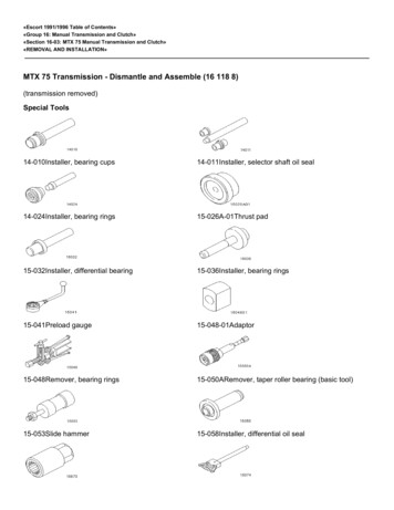
ADM X3Mobile Bearing Hip SystemSurgical ProtocolStep 1:Pre-operative Planning and X-rayEvaluation Pre-operative planning and X-ray evaluation aids inthe selection of the most favorable implant style andoptimal size for the patient’s hip pathology. Selectingpotential implant styles and sizes can facilitateoperating room preparation and assure availabilityof an appropriate size selection. X-ray evaluation may also help detect anatomicanomalies that could prevent the intra-operativeachievement of the established pre-operative goals.Step 2:Acetabular Preparation The acetabulum is prepared by the release andremoval of soft tissue using the surgeon’s preferredtechnique to gain adequate exposure for reaming.Excision of the labrum and osteophytes allows forproper visualization of the bony anatomy, andimproves ease of reaming.Note: Careful identification and removal of osteophytescan help reduce the possibility of bone-to-bone orcomponent-to-bone impingement.Figure 1 Stryker Orthopaedics’ Femoral and Wing Retractorscan be utilized to gain acetabular exposure (Figure 1).With the acetabulum exposed, bony defects canbe identified. If necessary, bone grafting optionsmay be considered prior to reaming.Step 3:Spherical ReamingCaution: Only the CuttingEdge Spherical Reamershould be used to prepare the acetabulum forRestoration ADM components. To obtain congruity in the reaming process, a45 /20 Abduction/Anteversion Alignment Guidecan be attached to the CuttingEdge ReamerHandle (Figure 2).Figure 24
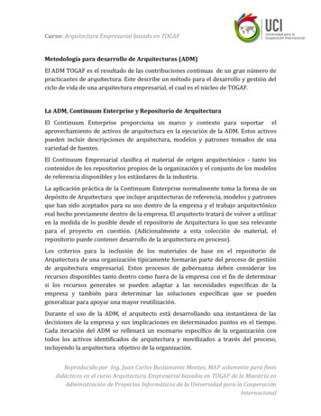
Surgical Protocol45 The alignment guide, when perpendicular to thelong axis of the patient, will orient the reamer handleat 45 of abduction, thereby placing the axis of thespherical reamer at 45 of inclination (Figure 3).The reamer handle may be positioned at 20 ofanteversion by aligning the left/right anteversionrod on the alignment guide so that it is parallel tothe long axis of the patient.Caution: All external alignment guides depend on thepatient being oriented in a lateral decubitus position.Figure 3Note: Changes in pelvic tilt and pelvic flexion causedby patient positioning on the table as well as disease inthe contralateral hip, spine and pelvis may impact asurgeon’s ability to achieve component placement at45 /20 abduction/anteversion. It is recommended that the initial reaming begin witha CuttingEdge Spherical Reamer that is 4mm smallerthan the templated or gauged size. The reamer isattached to the reamer handle by pushing down andapplying a quarter-turn to lock in place. Reamingprogresses in 1mm increments until final sizingis achieved. Ream line-to-line for the RestorationADM Cup. The Restoration ADM Cup periphery is 1.5mmlarger than the stated size (e.g., 52mm cup 53.5mmat the rim of the cup). The size of the RestorationADM Cup selected should be the same as the largestdiameter of the CuttingEdge Spherical Reamer used.Surgical judgment is used to assess bone stock, amountof interference, and proper amount of under-reaming.When implanting the Restoration ADM Cup, 1.5mmof interference fit is not always necessary when dense,hard, sclerotic bone is encountered. In this situation it isrecommended to over-ream by 1mm, thus leading to aninterference fit of 0.5mm. This may reduce the potentialfor problems that typically occur in dense bone such asacetabular fracture or failure to fully seat the implant.Note: The amount of interference fit should bedetermined intra-operatively based upon the patient’sbone quality.5
ADM X3Mobile Bearing Hip SystemSurgical ProtocolLockingSleeve The full profile of the CuttingEdge Spherical Reamernecessitates reaming to the full depth. The reamerhead should be driven to the point where the rim/cross bar contacts the acetabular wall at the peripherallunate region. Removal of the reamer from the handleis performed by pulling back on the locking sleeveand rotating the reamer head a quarter-turn in aclockwise direction (Figure 4). Care should be taken so as not to enlarge or distortthe acetabulum by eccentric reaming. Ream to theunicortical plate to medialize the cup. Ream to thefull depth of the CuttingEdge Spherical Reamer toseat the reamer in the socket.Figure 4Note: Restoration ADM acetabular cups contain a1.5mm peripheral press-fit built into the cup asmarked (e.g., 52mm cup 53.5mm).Note: The CuttingEdge Spherical Reamers are veryaggressive and perform best when sharp. Care shouldbe taken to protect the reamer from unnecessaryhandling, as dull or damaged cutting teeth may causeimproper reaming. Dull cutting teeth will deflect tocut softer bone and resist hard bone. This situationmay result in an irregularly shaped or enlargedacetabulum preparation.Step 4:Trial Evaluation of the Restoration ADMCupWindow TrialTrial Cup HolderFigure 5 Following the reaming procedure, the appropriateRestoration ADM Window Trial of the same diameteras the last spherical reamer used, either left or right, islocked onto the Restoration ADM Trial Cup Holder.This is done by pulling the locking mechanism andreleasing it after the window trial is set. The windowtrial is then placed in the acetabulum to evaluate thesize and congruity of the preparation (Figure 5). Thetrial is “windowed” for visualization and assessmentof fit, contact and congruency of the trial within theacetabulum. The Restoration ADM Window Trial has an exact fitinto the acetabulum (size for size), whereas the finalimplant has a press-fit of 1.5mm.6
Psoas ParvusPsoas MagnusADM X3SystemWindow TrialIliopsoasValleyWindow TrialReference MarkFigure 6Important: The design of the cup enables it toanatomically fit into the shape of the natural acetabulum,preventing impingement with the iliopsoas tendon. TheRestoration ADM Window Trial incorporates groovesthat must be positioned in regard to the iliopsoas tendon.Once the window trial is set, it is recommended to makea mark on the acetabulum at the level of the superiorreference mark (Figure 6). This reference mark willprovide a guideline for placing the final implant. TheRestoration ADM implant should be positioned so thatthe superior mark on the cup is aligned with the markon the acetabulum.Note: A mark or series of marks can be made at the rimof the window trial to provide a depth reference forseating the implant.Step 5:Restoration ADM Cup Implantation Assess acetabulum and surrounding soft tissue priorto cup introduction to ensure nothing is preventingcup implantation.Cup HolderHandleCup HolderRodFigure 7ExpandableCouplerCup Holder Rod(Distal)Cup HolderHandle Select the appropriately sized, left or right,Restoration ADM cup as clearly identified on theproduct label. Ensure the patient is in the correctposition. At this step it is prudent to re-assess patientpositioning in the surgical field. To facilitate the insertion of the cup, the RestorationADM Cup Holder must be assembled as detailedbelow. For each cup diameter (48mm – 64mm) thereis a corresponding expandable coupler.Cup Impactor Assembly: First, insert the Cup HolderRod into the proximal end of the Cup Holder Handle,snapping the two components together (Figure 7).Then, assemble the Expandable Coupler, correspondingto the size of the cup to be implanted, onto the distalportion of the Cup Holder Rod (Figure 8). Once theExpandable Coupler is placed onto the Cup Holder Rod,insert the wing nut through the top of the ExpandableCoupler (Figure 9). To engage the wing nut and to ensurethat all components are securely assembled, turn the cupholder rod clockwise (holding it vertically).Figure 857
ADM X3Mobile Bearing Hip SystemSurgical ProtocolStep 5:Restoration ADM Cup Implantation(Continued)Wing NutExpandableCouplerNote: When securing all components, be sure to onlyturn the Cup Holder Rod several turns–just enough tolock all components together. Turning the Cup HolderRod too much or until tightened will expand thecoupler prematurely, preventing it from properly fittingonto the implant when preparing for implantation.Cup HolderHandleCup HolderRodFigure 9ImplantSuperiorPolarReferenceMarkGray StripeExpandableCouplerReferenceMarkGray StripeFigure 10Notice that the Expandable Coupler has a referencemark (that lines up with the axis of the handle) thatcorresponds to the superior reference mark on theimplant. The gray stripes engraved on either side of thereference mark on the Expandable Coupler indicate theposition of the cup notch (right or left) for the iliopsoastendon (Figure 10). While the implant is still in the packaging, place theCup Holder vertically into it, making certain to alignthe cup and the Expandable Coupler reference marksfor proper Cup Holder/implant orientation and fit(Figure 10). While maintaining the position of thecup, turn the Cup Holder handle to tighten the cuponto the end of the Cup Holder and prepare it forplacement into the acetabulum.Note: The Expandable Coupler must be fully seatedwithin the implant before tightening. Fully seating theExpandable Coupler can be achieved by pressing itvertically into the cup, while placed on a table. When fullyseated, begin tightening the Expandable Coupler onto thecup for a secure fit. Following these instructions will helpreduce the risk of the cup and Expandable Coupler/CupHolder from disengaging during impaction. Cup Placement: Locate the reference mark madepreviously on the acetabulum. Position the cupaccording to the preset reference mark. Positioningthe cup according to the preset reference markwill ensure proper anatomic cup placement. Impactthe cup into the acetabulum with the slotted mallet(1120-1000) (Figure 11). Once the cup is securelyimpacted, remove the cup holder from the cup byturning the cup holder rod counter-clockwise andpulling the cup holder backwards with minimal force.8
Surgical ProtocolImportant: If re-impaction is required, be sure to usethe same Expandable Coupler size as the final implant.Do not use a smaller Expandable Coupler size than thefinal implant as this will compromise the integrity of thecoupler, and may cause it to break. When re-impactingthe cup, the coupler must be contracted and then fullyexpanded in the cup prior to re-impaction. A Ball Impactor(1235-0-013)* can be used as a final option. However, caremust be taken to protect the inner surface of the cup.Note: Proper positioning of the Restoration ADM Cupwill minimize potential impingement and help provideoptimal stability and articulation between the cup, insertand head. As with any acetabular system, excessivevertical orientation and/or anteversion of the cup shouldbe avoided as this may lead to premature wear of thecomponents’ surfaces.Figure 11Caution must be taken when using the Ball and/or RimImpactor to avoid compromising the initial stability of the cup.*These instruments have a limited life expectancy; deformationis expected and should be checked before each use. The Balland Rim Impactor tip must be changed if deformation orcracks are visible. Periodic replacement is required.It is recommended to use the slotted mallet (1120-1000) forimpaction of the Ball and Rim Impactor tips.Final CupImpactor HandleTo aid in proper cup positioning, a Rim Impactor(1235-0-014)* can be used to adjust version of the cupby impacting only on the rim.Please note that the Ball and Rim Impactor tips needto be assembled onto the Final Cup Impactor Handle(2101-0130) which comes pre-assembled with a blunttip. Please unscrew the tip in order to assemble the Rimor Ball Impactor tips (Figure 12).The Cup Impactor must be dis-assembled and placedinto the appropriate spots in the tray to ensure propercleaning and sterilization. After cleaning, threadlubrication is recommended.2101-0130 - Final Cup Impactor Handle1235-0-013 - Ball Impactor Tip1235-0-014 - Rim Impactor TipBall Impactor TipStep 6:Insert/Head Trial ReductionRim Impactor TipFigure 12Insert TrialHead Trial After metal cup implantation, there is an option touse either the ADM/MDM Dual Articulating Trials orthe ADM/MDM Monopolar Trials*. Both trialingoptions will facilitate a final check of hip mechanics toinclude range of motion consistent with the patient’snormal daily activities. At this point joint laxityshould also be assessed, taking into consideration thetype of anesthetic used and its effects on soft tissue. If using the ADM/MDM Dual Articulating Trials, placethe 28mm Head Trial into the appropriate Insert Trialto mimic the final articulation function of the ADMSystem (Figure 13a). The size of the insert trial willcorrespond with the cup being implanted (Table 1). Whenimplanting a 54mm shell for instance, a 54mm InsertTrial (28/54/48G) and 28mm Head Trial should be used.Insert TrialADM/MDM Dual Articulating TrialsFigure 13a*Note: The Monopolar Trials are only available for V40 andC-Taper heads. The Monopolar Trials are marked ‘trial donot implant’. If there is any reason to believe that the trialhas been accidentally implanted, the Monopolar InsertTrial is radiopaque and would be visible on an X-Ray.9
ADM X3Mobile Bearing Hip SystemSurgical ProtocolADM ShellOuter DiameterInsert TrialTrialSleeveInner Diameter ofthe CorrespondingADM/MDM InsertStep 6:Insert/Head Trial Reduction (Continued)MDMCoCrLiner Size If using the ADM/MDM Monopolar Trials, choose theTrial Sleeve that corresponds to the desired femoral headtaper and offset and assemble it into the appropriateInsert Trial by firmly pushing the sleeve into the innergeometry of the Insert Trial (Figure 13b, Tables 1-3).Correct assembly of the Trial Sleeve and Insert Trialswill produce an audible click. The size of the Insert Trialwill correspond with the cup being implanted (Table 1). Place the assembled Dual Articulating or MonopolarTrials onto the neck trial or stem trunnion component.Ensure that the Monopolar Trials are locked by firmlypushing the Insert Trial Sleeve assembly onto the necktrial or stem. Reduce the hip, checking for hip stabilityand the restoration of leg length. Fine tuning of hipjoint mechanics may be achieved with the use ofdifferent /- offsets.Part NumberADM/MDM Monopolar TrialsFigure 13bTable 1: ADM Shell, Insert and Femoral Head CompatibilityADM Shell ADM Shell ADM/MDM ADM/MDM ADM/MDMLeftRightX3 InsertDurationDualInsertArticulatingInsert TrialRequiredFemoralHead Size(mm)ADM/MDMMonopolarInsert te: Inserts are compatible with Stryker 28mm heads only.Note: With the launch of the monopolar trials, all traysmoving forward will have the same catalog number (1235-0300) along with updated markings to provide guidance on themonopolar trial placement. You will be able to distinguishbetween an original tray and a new tray as the original will notspecify ‘sleeves’ on the lid.10If a tray is being used that was launched prior to themonopolar trials, the following guidelines must be followed: The new monopolar insert trials (1235-0-XXXM) fitin the same location as the dual articulating trialinserts (1235-0-8XX). The new monopolar sleeve trials(1235-V-XXXX and 1235-C-XXXX) fit in the same areamarked for the head supporting piece (1235-0-009).
Surgical Protocol Once hip stability and leg length have been checked,the Dual Articulating or Monopolar Trial assemblycan be removed from the neck trial or trunnion as oneunit. If using the Monopolar Trials, the Trial Sleevecan then be removed from the Insert Trial with theassistance of standard Kocher forceps by squeezingthe Trial Sleeve and pulling it out of the Insert Trial(Figure 13c). This can also be accomplished by hand.Note: When using dual mobility implants, impingementshould be carefully assessed and avoided during rangeof motion. Impingement can result in increased wear inmetal polyethylene systems.Position of Kocher Forceps for Sleeve RemovalFigure 13cTips: Paul Perona, M.D.When using the ADM/MDM Dual ArticulatingTrials, place the 28mm trial head onto the neck trialor stem trunnion and place the ADM/MDM InsertTrial into the cup. The smaller trial head can thenbe reduced into the Insert Trial for ease ofreduction.Table 2: Monopolar Trial Sleeve Catalog Numbers and V40 28mm Femoral Head OptionsV40 28mm FemoralMonopolarLFIT CoCr BIOLOX delta BIOLOX deltaAluminaHead OffsetsTrial SleeveUniversal -4mm1235-V-0040-2.7mm1235-V-0027-2.5mm1235-V-0025 0mm1235-V-1000 4mm1235-V-1040 6mm1235-V-1060 8mm1235-V-1080 12mm1235-V-1120 Table 3: Monopolar Trial Sleeve Catalog Numbers and C-Taper 28mm Femoral Head OptionsC-Taper 28mm Femoral MonopolarLFIT CoCr BIOLOX delta BIOLOX deltaAluminaHead OffsetsTrial SleeveUniversal-3mm1235-C-0030-2.5mm1235-C-0025 0mm1235-C-1000 2.5mm 1235-C-1025 5mm1235-C-1050 7.5mm1235-C-1075 10mm1235-C-1100 11
ADM X3Mobile Bearing Hip SystemSurgical ProtocolStep 7:Insert/Head ImplantationPress StandBack table assembly of the Insert and corresponding V40or C-Taper 28mm Head is required. (Figure 14)The following instructions must be carefully adhered to:Press Place the Press Stand flat on the back table and placethe Press onto the Press Stand Pin. Put the Femoral Head Supporting Piece into the baseof the Press.Head Supporting PieceFigure 14Note: Ensure that the inside of the shell is clean andfree of soft tissue or other debris, which could prevent thepolyethylene insert from properly seating in the shell.Warning: A metal or ceramic head should not be used inplace of the dual mobility insert/head. The RestorationADM cup is not intended for use as a metal-on-metalor ceramic-on-metal articulation. No testing has beenconducted to determine that these bearing couples producefavorable mechanical outcomes. Open the press by turning the T-handle counterclockwise until the polyethylene insert fits above thefemoral head and below the plastic cone portion ofthe press. Place the Femoral Head onto the Head SupportingPiece, and then place Insert onto the Femoral Head. Once the Femoral Head and polyethylene insert are ina vertical position, tighten the Press until the head isfully lodged into the insert. After insertion, the airconfined between the head and insert is usuallyreleased, resulting in a characteristic noise. After the head and insert are assembled, verify thatthe coupling has complete mobility.Only Stryker 28mm femoral heads should be inserted intothe ADM polyethylene inserts.Step 8:Reduction and Closure Once the Insert and Head are assembled, the unit isready for implantation and reduction. Place insert/head unit onto the trunnion of thefemoral stem and slightly impact with insertreduction tool.Insert Reduction ToolFigure 1512 Then, by exerting axial traction on the limb andpressure on the insert using the insert reductiontool (Figure 15), reduce the hip and check for laxityand range of motion. The surgical site is then closedaccording to surgeon preference.
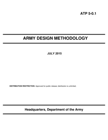
ADM X3Mobile Bearing Hip SystemSurgical ProtocolRemoval of CupProximalShould removal of the metal cup become necessary,an osteotome or small burr can be passed around thecup periphery to loosen the fixation interface.Removal of Insert and Head UnitNote: Once the insert and femoral head are assembled,the two components cannot be dis-assembled. However,the assembled insert and femoral head unit can beremoved from the trunnion of the stem.DistalFigure 16If the Restoration ADM insert and head unit needs tobe revised for any reason, remove the insert and headunit with the Femoral Head Remover Instrument(6059-9-505 - Figure 16). Place distal portion of the femoral head removerinstrument over the neck of the stem, while placingthe proximal portion of the instrument under the insertand head unit. Once the instrument is in position, squeeze thehandles together to pry the insert and head unit offof the trunnion of the stem.13
14
Catalog Information17
ADM X3Mobile Bearing Hip SystemSurgical ProtocolCatalog InformationRestoration ADM General Instrument TrayCatalog #Part Description1235-0-300General Instrument Tray1235-0-000Trial Cup Holder1235-0-020Insert Reduction Tool1235-0-008Press1235-0-012Press Stand1235-0-009Head Supporting PieceADM/MDMDualArticulatingInsert TrialRequiredFemoralHead Size(mm)ADM/MDMMonopolarInsert -864MNote: Either the Dual Articulating or Monopolar Trials will fit in this tray(1235-0-300). Only one system will fit in the tray at one time.16
Surgical ProtocolRestoration ADM Right Instrument TrayCatalog #Part Description1235-0-301Restoration ADM Right Cup Instrument Tray1235-0-461Restoration ADM Window Trial Right 46mm1235-0-481Restoration ADM Window Trial Right 48mm1235-0-501Restoration ADM Window Trial Right 50mm1235-0-521Restoration ADM Window Trial Right 52mm1235-0-541Restoration ADM Window Trial Right 54mm1235-0-561Restoration ADM Window Trial Right 56mm1235-0-581Restoration ADM Window Trial Right 58mm1235-0-601Restoration ADM Window Trial Right 60mm1235-0-621Restoration ADM Window Trial Right 62mm1235-0-641Restoration ADM Window Trial Right 64mmRestoration ADM Left Instrument TrayCatalog #Part Description1235-0-302Restoration ADM Left Cup Instrument Tray1235-0-462Restoration ADM Window Trial Left 46mm1235-0-482Restoration ADM Window Trial Left 48mm1235-0-502Restoration ADM Window Trial Left 50mm1235-0-522Restoration ADM Window Trial Left 52mm1235-0-542Restoration ADM Window Trial Left 54mm1235-0-562Restoration ADM Window Trial Left 56mm1235-0-582Restoration ADM Window Trial Left 58mm1235-0-602Restoration ADM Window Trial Left 60mm1235-0-622Restoration ADM Window Trial Left 62mm1235-0-642Restoration ADM Window Trial Left 64mm17
ADM X3Mobile Bearing H
This surgical protocol is a guide to preparing the acetabulum for the Restoration ADM acetabular implants utilizing Restoration ADM acetabular instruments and Cutting Edge acetabular reamers. The Restoration ADM acetabular system is a two-piece component design that is assembled intra-operatively. Restoration ADM acetabular cups have a peripheral