Transcription
Installation andQuick ConfigurationManualNetBotz Rack Monitor 450/550/570NBRK0450NBRK0550NBRK0570
This manual is available in English on the enclosed CD.Dieses Handbuch ist in Deutsch auf der beiliegenden CD-ROM verfügbar.Este manual está disponible en español en el CD-ROM adjunto.Ce manuel est disponible en français sur le CD-ROM ci-inclus.Questo manuale è disponibile in italiano nel CD-ROM allegato.O manual em Português está disponível no CD-ROM em anexo. CD ᛘਟԕӾवਜ਼Ⲵ &' к㧧ᗇᵜ Ⲵѝ᮷ ᵜDŽ ⸽ Gjk 㙼㜄G䚐ạ㛨G 㛰㢨G㢼 U
ContentsIntroduction . 1Product Description . . . . . . . . . . . . . . . . . . . . . . . . . . . . . . . . . . . . . . . 1Document Overview . . . . . . . . . . . . . . . . . . . . . . . . . . . . . . . . . . . . . . . 1Related Documents. . . . . . . . . . . . . . . . . . . . . . . . . . . . . . . . . . . . . . . . 1Additional Options . . . . . . . . . . . . . . . . . . . . . . . . . . . . . . . . . . . . . . . . 1InfraStruxure-certified . . . . . . . . . . . . . . . . . . . . . . . . . . . . . . . . . . . . . 2Physical Description. 3Inventory . 5Installation . 6Install the Appliance . . . . . . . . . . . . . . . . . . . . . . . . . . . . . . . . . . . . . . . 6Rack-mount installation . . . . . . . . . . . . . . . . . . . . . . . . . . . . . . . . . . . 7Power cord and network cable connections . . . . . . . . . . . . . . . . . . 8Connect Sensors to Sensor Ports. . . . . . . . . . . . . . . . . . . . . . . . . . . . 9Connect an Alarm Beacon and Other Optional Devices . . . . . . . . . 10Connect Sensors and Sensor Pods to A-Link Ports . . . . . . . . . . . . 11Initial Configuration . 13Overview . . . . . . . . . . . . . . . . . . . . . . . . . . . . . . . . . . . . . . . . . . . . . . . 13Obtain network settings using DHCP . . . . . . . . . . . . . . . . . . . . . . . 13Configure network settings using the serial configuration utility 14Install a wireless network device . . . . . . . . . . . . . . . . . . . . . . . . . . 15The NetBotz Configuration Wizard . . . . . . . . . . . . . . . . . . . . . . . . . . 16NetBotz Rack Monitor 450/550/570 Installation and Quick Configuration Manuali
Access an Appliance . . . . . . . . . . . . . . . . . . . . . . . . . . . . . . . . . . . . . 16Overview . . . . . . . . . . . . . . . . . . . . . . . . . . . . . . . . . . . . . . . . . . . . . . . 16Administrator account user ID and password . . . . . . . . . . . . . . . . 16Root account user ID and password . . . . . . . . . . . . . . . . . . . . . . . . 17Lost password recovery . . . . . . . . . . . . . . . . . . . . . . . . . . . . . . . . . . 17Web Client . . . . . . . . . . . . . . . . . . . . . . . . . . . . . . . . . . . . . . . . . . . . . 18Advanced View . . . . . . . . . . . . . . . . . . . . . . . . . . . . . . . . . . . . . . . . . 18NetBotz Quick Configuration. . . . . . . . . . . . . . . . . . . . . . . . . . . . . . . 19Configure appliance settings . . . . . . . . . . . . . . . . . . . . . . . . . . . . . . 19Configure alert actions . . . . . . . . . . . . . . . . . . . . . . . . . . . . . . . . . . . 20Upgrade Options . 21Software Feature Upgrades . . . . . . . . . . . . . . . . . . . . . . . . . . . . . . . . 21Hardware Upgrades . . . . . . . . . . . . . . . . . . . . . . . . . . . . . . . . . . . . . . 21Add pods to your appliance . . . . . . . . . . . . . . . . . . . . . . . . . . . . . . . 22Connect a wireless sensor network . . . . . . . . . . . . . . . . . . . . . . . . . 24Connect a USB modem . . . . . . . . . . . . . . . . . . . . . . . . . . . . . . . . . . . 26Connect a USB digital I/O device . . . . . . . . . . . . . . . . . . . . . . . . . . . 26Connect an APC Switched Rack PDU . . . . . . . . . . . . . . . . . . . . . . . 27Connect external sensors . . . . . . . . . . . . . . . . . . . . . . . . . . . . . . . . . 27Disposal. 28Clean the NetBotz 450/550/570. 28Specifications . 29Sensor Specifications . . . . . . . . . . . . . . . . . . . . . . . . . . . . . . . . . . . . 30Warranty . 31Two-Year Factory Warranty . . . . . . . . . . . . . . . . . . . . . . . . . . . . . . . . 31Terms of warranty . . . . . . . . . . . . . . . . . . . . . . . . . . . . . . . . . . . . . . . 31Non-transferable warranty . . . . . . . . . . . . . . . . . . . . . . . . . . . . . . . . 31Exclusions . . . . . . . . . . . . . . . . . . . . . . . . . . . . . . . . . . . . . . . . . . . . . 31Warranty claims . . . . . . . . . . . . . . . . . . . . . . . . . . . . . . . . . . . . . . . . . 32iiNetBotz Rack Monitor 450/550/570 Installation and Quick Configuration Manual
Radio Frequency Interference . . . . . . . . . . . . . . . . . . . . . . . . . . . . . .35USA — FCC . . . . . . . . . . . . . . . . . . . . . . . . . . . . . . . . . . . . . . . . . . . . . 35Canada — ICES . . . . . . . . . . . . . . . . . . . . . . . . . . . . . . . . . . . . . . . . . . 35Japan — VCCI . . . . . . . . . . . . . . . . . . . . . . . . . . . . . . . . . . . . . . . . . . . 35Taiwan—BSMI . . . . . . . . . . . . . . . . . . . . . . . . . . . . . . . . . . . . . . . . . . 35Australia and New Zealand . . . . . . . . . . . . . . . . . . . . . . . . . . . . . . . . 35European Union . . . . . . . . . . . . . . . . . . . . . . . . . . . . . . . . . . . . . . . . . 35NetBotz Rack Monitor 450/550/570 Installation and Quick Configuration Manualiii
IntroductionProduct DescriptionThe Schneider Electric NetBotz Rack Monitor 570, Rack Monitor 550 or Rack Monitor 450 functionsas the central hardware appliance for a NetBotz security and environmental monitoring system. Therack-mountable appliance includes multiple ports for connecting APC environmental sensors and otherthird-party sensors. The appliances include additional ports that provide power to or allow control overother devices. With a NetBotz 570, 550, or 450, you can increase the space monitored. With a NetBotz570 or 550, you can add up to twelve NetBotz sensor pods. With a NetBotz 450, you can add up to twoNetBotz sensor pods.Document OverviewThe NetBotz Rack Monitor 450/550/570 Installation and Quick Configuration Manual describes how toinstall a NetBotz Rack Monitor 450, 550, or 570, how to connect devices to the appliances, and how toconfigure network settings. After performing the configuration procedures in this manual, you canaccess your system through its software interface, perform additional configuration tasks, and beginmonitoring the environment.Related DocumentsUnless otherwise noted, the following documentation is available on the CD provided with the device oron the applicable product page on the APC Web site, www.apc.com. To quickly find a product page,enter the product name or part number in the Search field.NetBotz Appliance User’s Guide – Includes all details for using, managing, and configuring a NetBotzsystem with one of the following appliances: NetBotz Room Monitor 355 (NBWL0355, NBWL0356),NetBotz Rack Monitor 450 (NBRK0450), NetBotz Room Monitor 455 (NBWL0455, NBWL0456),NetBotz Rack Monitor 550 (NBRK0550), or NetBotz Rack Monitor 570 (NBRK0570).Additional OptionsThe following options are available for the appliance. For more information about any of the options,contact your APC representative or the distributor from whom you purchased your APC product. NetBotz Camera Pod 160 (NBPD0160) NetBotz Rack Sensor Pod 150 (NBPD0150) NetBotz Room Sensor Pod 155 (NBPD0155) Temperature Sensor (AP9335T) Temperature/Humidity Sensor (AP9335TH) Temperature Sensor with Digital Display (AP9520T) Temperature/Humidity Sensor with Digital Display (AP9520TH) Alarm Beacon (AP9324) NetBotz Spot Fluid Sensor (NBES0301)NetBotz Rack Monitor 450/550/570 Installation and Quick Configuration Manual1
NetBotz Door Switch Sensor for Rooms or Third Party Racks (NBES0302) NetBotz Door Switch Sensor for APC Racks (NBES0303) NetBotz Dry Contact Cable (NBES0304) NetBotz 0-5 V Sensor Cable (NBES0305) NetBotz Vibration Sensor (NBES0306) NetBotz Smoke Sensor (NBES0307) NetBotz Rope Leak Sensor (NBES0308) NetBotz Rope Leak Extension (NBES0309) NetBotz Particle Sensor PS100 (NBES0201) NetBotz USB-to-Serial Cable (NBAC0226) Power Supply 100-230 VAC/24 VDC (AP9505i) NetBotz 4-20mA Sensor Pod (NBPD0129) NetBotz CCTV Adapter 120 with USB Cable (NBPD0123) NetBotz Sensor Pod 120 (NBPD0122) NetBotz Camera Pod 120 (NBPD0121) NetBotz Rack Access Pod 170 (NBPD0170) (for NBRK0550 and NBRK0570 only) NetBotz Rack Access Electronic Handle (NBHN0170) (for NBRK0550 and NBRK0570only)NBHN017BHN0171 NetBotz Wireless Sensor Pod 180 (NBPD180) NetBotz USB Coordinator & Router (NBWC100U) NetBotz Wireless Temperature Sensor (NBWS100T and NBWS100H)InfraStruxure-certifiedThis product is certified for use in APC InfraStruxure systems.2NetBotz Rack Monitor 450/550/570 Installation and Quick Configuration Manual
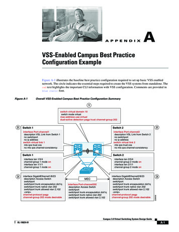
Physical DescriptionItemDescription AC line inletProvides for the input power connection; see “Specifications” on page 29 for voltageinformation. Reset switchResets the appliance. Port activity LEDFlashes green when the RS485 port is receiving. Only available on the NBRK0570appliance. RS485 portProvides for a Modbus connection. Only available on the NBRK0570 appliance. 10/100 Base-T Network Provides for a 10/100 Base-T network connection. Status and link LEDs indicate networkPorttraffic: Status LED—blinks orange and green at start-up; indicates the status of the networkconnection (solid green—IP address established; blinking green—attempting to obtainan IP address). Link LED—blinks to indicate network traffic (green—connected at 10 Mbps; orange—connected at 100 Mbps). Alert LEDIndicates the alert status of the system. When more than one alert exists, the most severewill be indicated. Flashing once every eight seconds—Informational Flashing once every four seconds—Warning Flashing once every two seconds—Error Flashing once every second—Critical Flashing twice per second—Failure Voltage OutputProvides 12 VDC or 24 VDC (75 mA) to one connected device.Relay Output Ports 1, 2 Used for connecting relay-controlled external devices. Provides 24 VDC (100mA) each. Power LEDIndicates whether the unit is receiving power (green—receiving power; dark—notreceiving power). 4-20 mA InputsProvides 24 VDC for connecting third-party sensors with an input current range from 4 to20 mA. Sensor portsUsed for connecting APC sensors, third-party dry-contact sensors, and standard thirdparty 0-5 V sensors. (See “Additional Options” on page 1 for details on APC sensoroptions.) Third-party dry-contact state sensors require the NetBotz Dry Contact Cable(NBES0304). Standard third-party 0-5 V sensors require the NetBotz 0-5 V Sensor Cable(NBES0305). NBRK0450/550 - 5/24 VDC (50mA). NBRK0570 - 5/24 VDC (200mA). Leak Rope portUsed for connecting a NetBotz Rope Leak Sensor (NBES0308) Beacon portUsed for connecting an Alarm Beacon (AP9324).NetBotz Rack Monitor 450/550/570 Installation and Quick Configuration Manual3
Item4Description A-Link portUsed for cascading NetBotz sensor pods and temperature and humidity sensors withdigital displays. Provides communications and power to the connected devices overstandard CAT-5 cabling with straight-through wiring. For details, see “Connect Sensorsand Sensor Pods to A-Link Ports” on page 11. Alert LEDSame as item 4 above. Power LEDIndicates whether the unit is receiving power (green—receiving power;dark—not receiving power). Console PortUsed to connect a console to the appliance. Enable the USB-to-serial converter support(FTDI) in your operating system. USB Type A ports(2 or 4)Used to connect USB devices to the appliance. The NBRK0550 and NBRK0450 havetwo USB ports, while the NBRK0570 has four. Exhaust fanExhausts hot air from the NBRK0570. Not present on the NBRK550 or NBRK450.NetBotz Rack Monitor 450/550/570 Installation and Quick Configuration Manual
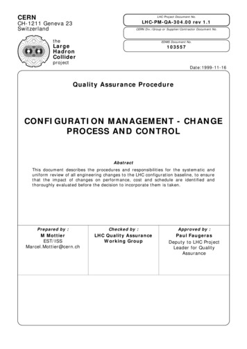
InventoryInspect the contents of the package to ensure that the parts included match those shown below. Reportmissing or damaged contents to APC or your APC reseller. However, if damage was due to shipping,immediately report the damage to the shipping agent.The shipping and packaging materials are recyclable. Please save them for later use or disposeof them appropriately.ItemDescription NetBotz Rack Monitor 450, Rack Monitor 550 or Rack Monitor 570 Brackets for a standard 19-in rack M4 x 8 Phillips flat-head screws Power cord retainer bracket 8-position terminal block plug 9-position terminal block plug 203-mm (8-in) tie wraps NetBotz Appliance Utility CD 203-mm (8-in) hook and loop cable strap 1.8-m (6-ft) IEC-320-C13 to IEC-320-C14 power cord 1.8-m (6-ft) NEMA 5-15P to IEC-320-C13 power cord 5-m (16.4-ft) USB cable 3-position terminal block plugTemperature/Humidity Sensor (AP9335TH)—not shownNetBotz Rack Monitor 450/550/570 Installation and Quick Configuration Manual5
InstallationInstall the ApplianceInstall the appliance in the front or the rear of the rack or enclosure using the rack-mount procedure,which requires 1 U of rack space. When installing the appliance, take into consideration the following:Caution: Only connect approved devices to ports on the appliance as directed in this manual.Plugging in other devices may result in equipment damage.Note: Install the appliance in an environment compatible with the maximum ambienttemperature (Tma) specified in “Specifications” on page 29. Appliances installed in a closedor multi-unit rack assembly can experience a greater operating ambient temperature than theambient room temperature.Note: Install the appliance in a way that allows sufficient airflow for safe operation.Note: When you install the appliance in the rack, be sure that you do not create a hazardouscondition due to uneven mechanical loading. For example, do not use the appliance as a shelf.6NetBotz Rack Monitor 450/550/570 Installation and Quick Configuration Manual
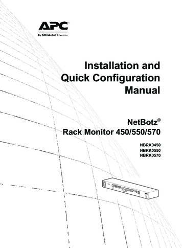
Rack-mount installation1. Choose a location for the appliance in the front or rear of the rack. Theappliance occupies one U-space. A notched hole or a number on the rackvertical rail denotes the middle of a U-space.Caution: To avoid equipment damage, use only the hardwareprovided when installing the brackets.2. Install the brackets ( and ),including the power cord retainerbracket, on the end nearest the AC LineInlet. M4 x 8 Phillips flat-head screws Bracket Power cord retainer bracket3. Secure the appliance to the rack, using cagenuts and screws (provided with the rack).NetBotz Rack Monitor 450/550/570 Installation and Quick Configuration Manual7
Power cord and network cable connectionsCaution: Before you energize the appliance, review the electrical specifications on page 29to avoid overloading the circuit.Caution: Make sure you properly ground the appliance by plugging the power cord directlyinto a wall outlet or by verifying the ground path if using a power strip.Note: The power cords provided are to be used only with APC NetBotz products.1. Connect the appropriate power cord to the AC Line Inlet of the appliance.2. Secure the power cord to the power cord retainer bracket using the tie wraps.3. Connect a network cable to the 10/100 Base-T Network Port on the appliance.4. Plug the power cord into a power source.5. Use the hook and loop cable strap to secure the cables.8NetBotz Rack Monitor 450/550/570 Installation and Quick Configuration Manual
Connect Sensors to Sensor PortsThis procedure applies to the following sensors, which are supported by the appliance and connect to thesensor ports: Temperature Sensor (AP9335T) Temperature/Humidity Sensor (AP9335TH) NetBotz Vibration Sensor (NBES0306) NetBotz Smoke Sensor (NBES0307) NetBotz Spot Fluid Sensor (NBES0301) NetBotz 0-5 V Sensor Cable (NBES0305) NetBotz Door Switch Sensor for APC Racks (NBES0303) NetBotz Door Switch Sensor for Rooms or Third Party Racks (NBES0302) NetBotz Dry Contact Cable (NBES0304)For sensors that connect to A-Link ports (Temperature Sensors with Digital Display[AP9520T] and Temperature/Humidity Sensors with Digital Display [AP9520TH]),see “Connect Sensors and Sensor Pods to A-Link Ports” on page 11.Connect APC and third-party sensors to the six sensor ports labeled Sensors on the appliance. Third-party dry contact sensors require the NetBotz Dry Contact Cable (NBES0304). To connecta sensor to the cable, follow the instructions provided with the sensor and the instructionsprovided with the cable. Standard third-party 0-5 V sensors require the NetBotz 0-5 V Sensor Cable (NBES0305). Toconnect a sensor to the cable, follow the instructions provided with the sensor and the instructionsprovided with the cable. If a sensor cable is not long enough, use an RJ-45 coupling (provided with some sensors) andstandard CAT-5 cabling to extend the cable up to 15 m (50 ft) for a Temperature/Humidity Sensor(AP9335TH) or a Temperature Sensor (AP9335T) and up to 30.5 m (100 ft) for all othersupported sensors.Below is a list of the different pod/sensor types and the number of devices each appliance can support.:Pod/Sensor TypeRack Monitor 570Camera Pod 160Camera Pod 120total of 4 podsCCTV Adapter Pod 120Sensor Pod 150Sensor Pod 155total of 12 podsSensor Pod 1204-20 mA Input Pod 120Smoke Sensor2AP9520 Temp/Humidity8Probe (A-Link)* Installing four camera pods requires an external USB hub.Rack Monitor 550Rack Monitor 450total of 4 pods*total of 2 podstotal of 12 podstotal of 2 pods2288NetBotz Rack Monitor 450/550/570 Installation and Quick Configuration Manual9
Connect an Alarm Beacon and Other OptionalDevices1. Install an alarm beacon:– Install the alarm beacon in a visible position eitheron the roof of the rack or inside the rack.– Route the alarm beacon cable to the appliance.The alarm beacon cable may be extended to amaximum of 100 m (328 ft), using RJ-45couplings and standard CAT-5 cables.– Connect the cable to the Alarm Beacon port.2. Connect one device to the Voltage Output.Caution: Relay Outputs can only be connected to Class 2 circuits.3. Connect up to two devices to the Relay Outputs.4. Connect a NetBotz Rope Leak Sensor to the Leak Rope port.10NetBotz Rack Monitor 450/550/570 Installation and Quick Configuration Manual
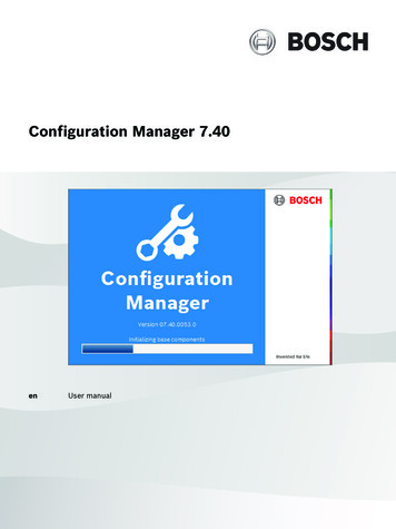
Connect Sensors and Sensor Pods to A-Link PortsWith a NetBotz 550 or NetBotz 570, you can cascade up to a combined total of twelve NetBotz RackSensor Pod 150s (NBPD0150) and NetBotz Room Sensor Pod 155s (NBPD0155) plus up to a combinedtotal of eight Temperature Sensors with Digital Display (AP9520T) and Temperature/Humidity Sensorswith Digital Display (AP9520TH). In addition, you can cascade up to a total of thirteen Rack Access Pod170s.With a NetBotz 450, you can cascade up to a combined total of two NetBotz Rack Sensor Pod 150s(NBPD0150) and NetBotz Room Sensor Pod 155s (NBPD0155), plus up to a combined total of eightTemperature Sensors with Digital Display (AP9520T) and Temperature/Humidity Sensors with DigitalDisplay (AP9520TH).You cannot cascade appliances. Use one appliance per system. A-Link is an APC proprietary CAN(Controller Area Network) bus. Devices compatible with A-Link are not Ethernet devices and cannotcoexist on an Ethernet bus with other networking devices, such as hubs and switches.Before performing this procedure, follow the installation instructions provided with the devices you arecascading. If you cascade more than ten sensor pods, be sure you have a supplemental power supply(Power Supply 100-230 VAC/24 VDC—AP9505i) to connect to your system as directed in thisprocedure. If you cascade more than four Rack Access Pod 170s, you will need an additional powersupply for every four Rack Access Pods. The NetBotz 570 does not require an external power supply.1. Connect sensors and sensor pods to theappliance as shown.– Use CAT-5 (or equivalent) Ethernetpatch cables ( . Caution: Do notuse crossover cables.NetBotz RackMonitor 450(NBRK0450)– Connect to in and out ports as shown.– The maximum combined length of allA-Link cables must notexceed 1000 m (3,280 ft).2. Plug an A-Link terminator into theunused A-Link port ( ).NetBotzRack SensorPod 150(NBPD0150)NetBotzRack SensorPod etBotz Rack Monitor 450/550/570 Installation and Quick Configuration Manual11
Caution: The first time a sensor pod receives power, it obtains a uniqueidentification address for communication over the A-Link bus. To avoidcommunication problems, you must complete steps 1 and 2 before you connect asupplemental power supply.3. With a Rack Monitor 450 or 550, if you have cascaded ten or more devices, connect onesupplemental power supply (AP9505i) to the 24 VDC Input jack of the Rack Sensor Pod 150 orthe Room Sensor Pod 155 in or closest to the eleventh position.12NetBotz Rack Monitor 450/550/570 Installation and Quick Configuration Manual
Initial ConfigurationNote: Disregard the procedures in this section if you have an APC InfraStruxure Centralserver as part of your system. See the documentation for your InfraStruxure device for moreinformation.OverviewYou must configure the following TCP/IP settings before the appliance can operate on a network: IP address of the appliance Subnet mask Default gatewayNote: If a default gateway is unavailable, use the IP address of a computer that islocated on the same subnet as the appliance and that is usually running. The applianceuses the default gateway to test the network when traffic is very light.Obtain network settings using DHCPBy default, your appliance obtains its network settings using DHCP. When you connect the appliance toyour network and apply power to the unit, it automatically attempts to contact a DHCP server. Theappliance waits 30 seconds for a response. If the DHCP server is configured to provide a hostname, theappliance requests either its configured hostname or ‘netbotzxxxxxx’ (where xxxxxx is the last 6 digits ofthe MAC address of the appliance) as a hostname associated with the IP address granted by the DHCPserver. This enables you to use a Web browser to connect to the appliance using the addresshttp://netbotzxxxxxx without any additional configuration. The appliance also requests DNS serveraddresses, a DNS domain, SMTP server addresses, and NTP server addresses from the DHCP server.NetBotz Rack Monitor 450/550/570 Installation and Quick Configuration Manual13
Install the serial configuration utility and other programs. The NetBotz Serial ConfigurationUtility is a Java -based application that configures the network settings on your NetBotz appliance. Usethe NetBotz Appliance Utility CD to install the Serial Configuration Utility (Windows systems only), aswell as the Advanced View (the monitoring and management console for your NetBotz appliance) andthe Java Runtime Environment (JRE) on your system.Note: The Java Runtime Environment used by the Advanced View application is alwaysinstalled, regardless of whether the installation target already has a suitable JRE installed. Microsoft Windows Systems: To install the applications and the JRE on a computer runningWindows XP SP1 or SP2, Windows 2000, Windows Vista, or Windows 7, place the NetBotzAppliance Utility CD in the CD drive of the computer that you will use to configure and manageyour appliance. The NetBotz Installer starts automatically. If you have disabled Autorun on yourcomputer, click Start Run, type x:\av\windows\install.exe in the Open field (where xis the drive letter assigned to your CD drive) and click OK. Follow the prompts to complete theinstallation of your software. Linux Systems: To install the applications and the JRE on a computer running Red Hat Enterprise Linux 4 or 5, or Fedora Core 11 or 12, place the NetBotz Appliance Utility CD inthe CD drive of the computer that you will use to configure and manage your NetBotz appliance.Mount the drive if necessary. Run install.bin from the Linux subdirectory on the CD. Forexample, if you are using Linux and you mounted the CD drive as /mnt/cdrom, execute thefollowing command:sh /mnt/cdrom/linux/install.binFollow the prompts to complete the installation of your software.Configure network settings using the serial configuration utilityTo configure your appliance using the Serial Configuration Utility:1. Click Start Programs NetBotz Serial Configuration Serial Configuration Utility tostart the Serial Configuration Utility.2. Connect one end of a USB cable to your computer and the other end of the cable to the Consoleport on the NetBotz appliance.3. Plug the power cord provided with your NetBotz appliance into a wall outlet, and then connect itto the AC line inlet.Note: This power cord is to be used only with APC NetBotz products.The green Power LED illuminates immediately after you apply power to the appliance. The unitcan take up to two minutes to initialize, depending on appliance configuration. The red AlertLED illuminates when the appliance detects an alert condition. Click Next to continue.4. The Serial Configuration Utility automatically scans your system COM ports to determine if aNetBotz appliance is connected to the network. If a NetBotz appliance is discovered, theappliance is listed in the Device column of the window. Select the radio button for the applianceto configure and click Next to continue.14NetBotz Rack Monitor 450/550/570 Installation and Quick Configuration Manual
Note: If the COM port associated with the port to which your USB cable is connectedis currently in use by another application, the message beside the COM port in theOwner column indicates that the port is not available. To correct this, close theapplication that is using the COM port and click Scan Serial Ports.5. The Root Password window appears. Enter the administrator account password for this appliance(apc, by default) and click OK.6. Specify whether to use DHCP to specify the network settings of your appliance. Click Yes or No,and click Next to continue.7. The utility scans the appliance and displays the network settings stored on the appliance. Thenetwork settings are divided into Ethernet Card Settings and DNS Settings.8. Specify the Ethernet Card settings.– To use network settings assigned by a DHCP server, select Configure automatically viaDHCP.– To specify network settings for use by this appliance, select Configure using these settingsand provide an IP address, subnet mask, and gateway address for the appliance. Specify a NATproxy name or IP address to be used by a NAT Proxy server in your network to allow users toconnect to the appliance from outside the firewall. You can also specify speed and duplexsettings for use by this interface, or use the default setting, Auto Negotiate.9. Specify the DNS Settings.– To use DNS Settings provided by your DHCP server, check Use DHCP DNS Settings.– To specify DNS Settings for this appliance manually, clear the Use DHCP DNS Settingscheckbox and provide the domain and DNS server information.10.Click Next to save your configuration settings. Click Finish to close the Serial ConfigurationUtility.11. Test the IP connection of the NetBotz appliance. Start your Web browser and type the IP addressof the appliance into the address field. Press Enter. If the NetBotz appliance is online andproperly configured, the web client displays in the browser window.Install a wireless network deviceYou can install a third-party wireless network device by connecting it to the Ethernet port on theappliance using an Ethernet cable. APC currently supports the D-Link DWL-G820, a wireless Ethernetbridge.To install and configure a third-party wireless network device, see the instructions providedwith that device.NetBotz Rack Monitor 450/550/570 Installation and Quick Configuration Manual15
The NetBotz Configuration WizardUse the Configuration Wizard to configure the following settings on your appliance: Domain Name Server Settings Clock and Calendar Settings Region Settings Administrator User ID and Password E-Mail Settings E-Mail Alert Notification RecipientsThe Configuration Wizard downloads the latest available version of BotzWare to your appliance.When you finish configuring your appliance with the Wizard, your appliance monitors your environmentfor lack of adequate air flow and for changes in temperature and humidity and detects motion in the areain which the camera is located. Alert conditions detected by any of these sensors generate an e-mail tosend to a specified e-mail address.The Configuration Wizard runs each time you use the Advanced View with your NetBotz appliance untilyou complete all of the steps in the Wizard or check Don’t Show Configuration Wizard Next Time.You can run the Wizard again by selecting Configuration Wizard from the Advanced View Toolsdrop-down list.Access an ApplianceOverviewAfter the appliance is running on your network, you can access the configured appliance through the webclient or the Advanced View.Administrator account user ID and passwordYour NetBotz appliance has a pre-configured Administrator account. The User ID and Password for thisaccount are: User ID: apc Password: apcNote: To increase security, be sure to use the Advanced View Users task to change thedefault User ID and Password for the Administrator account.16NetBotz Rack Monitor 450/550/570 Installation and Quick Configuration Manual
Root account user ID and passwordYour NetBotz applianc
Voltage Output Provides 12 VDC or 24 VDC (75 mA) to one connected device. Relay Output Ports 1, 2 Used for connecting relay-controlled external devices. Provides 24 VDC (100mA) each. . Secure the power cord to the power cord retainer bracket using the tie wraps. 3. Connect a network cable to the 10/100 Base-T Network Port on the appliance.