Transcription
White PaperDell Reference ConfigurationDeploying Oracle Database 11g R1 Enterprise EditionReal Application Clusters withRed Hat Enterprise Linux 5.1 and Oracle Enterprise Linux 5.1On Dell PowerEdge Servers, Dell/EMC StorageAbstractThis white paper provides an architectural overview and configuration guidelines for deploying a two nodeOracle Database 11g R1 Real Application Cluster (RAC) on Dell PowerEdge servers with Red HatEnterprise Linux release 5 update 1 (RHEL5.1) and Oracle Enterprise Linux release 5 update 1 (OEL 5.1)on Dell/EMC storage. Using the knowledge gained through joint development, testing and support withOracle, this Dell Reference Configuration documents “best practices” that can help speed Oracle solutionimplementation and help simplify operations, improve performance and availability.April, 2008Dell Reference Configuration for Oracle 11g R1 on Red Hat Enterprise Linux 5.1 and Oracle EnterpriseLinux 5.11
THIS WHITE PAPER IS FOR INFORMATIONAL PURPOSES ONLY, AND MAY CONTAIN TYPOGRAPHICAL ERRORSAND TECHNICAL INACCURACIES. THE CONTENT IS PROVIDED AS IS, WITHOUT EXPRESS OR IMPLIEDWARRANTIES OF ANY KIND.Trademarks used in this text: Intel and Xeon are registered trademarks of Intel Corporation; EMC,Navisphere, and PowerPath are registered trademarks of EMC Corporation; Microsoft, Windows, andWindows Server are registered trademarks of Microsoft Corporation. Oracle is a registered trademark ofOracle Corporation and/or its affiliates. Red Hat is a registered trademark of Red Hat Inc. Linux is aregistered trademark of Linus Torvalds. Other trademarks and trade names may be used in this document torefer to either the entities claiming the marks and names or their products. Dell Inc. disclaims anyproprietary interest in trademarks and trade names other than its own.April 2008 Rev. A00Dell Reference Configuration for Oracle 11g R1 on Red Hat Enterprise Linux 5.1 and Oracle EnterpriseLinux 5.12
Table of ContentsABSTRACT . 1INTRODUCTION . 4DELL SOLUTIONS FOR ORACLE DATABASE 11G . 4OVERVIEW OF THIS WHITE PAPER . 4ARCHITECTURE OVERVIEW - DELL SOLUTIONS FOR ORACLE 11G ON RED HATENTERPRISE LINUX 5.1 AND ORACLE ENTERPRISE LINUX 5.1 . 5HARDWARE CONFIGURATION . 6STORAGE CONFIGURATION. 6Configuring Dell/EMC CX3 Fibre Channel Storage Connections with Dual HBAs and Dual FibreChannel Switches . 6Configuring Disk Groups and LUNs. 7SERVER CONFIGURATION . 10Each of the Oracle 11g RAC database cluster nodes should be architected in a highly availablemanner. The following sections will detail how to setup the Ethernet interfaces, the Fibre Channelhost bus adapters (HBAs). These are the two fabrics that the database uses to communicate with eachother and to the storage. Ensuring that these interfaces are fault tolerant will increase theavailability of the overall system. . 10Configuring Fully Redundant Ethernet Interconnects . 10Configuring Dual HBAs for Dell/EMC CX3 storage. 11SOFTWARE CONFIGURATION. 11OPERATING SYSTEM CONFIGURATION . 11Configuring the Private NIC Teaming. 11Configuring the Same Public Network Interface Name on All Nodes. 12Configuring SSH . 12Configuring Shared Storage for the Oracle Clusterware using the RAW Devices Interface. 12Configuring Shared Storage for the Database using the ASM Library Driver. 13ORACLE DATABASE 11G R1 CONFIGURATION. 14REFERENCE SOLUTION DELIVERABLE LIST – DELL SOLUTION FOR ORACLE 11G R1 ONORACLE ENTERPRISE LINUX 5.1. 15CONCLUSION. 16TABLES AND FIGURES INDEX . 17REFERENCES . 17Dell Reference Configuration for Oracle 11g R1 on Red Hat Enterprise Linux 5.1 and Oracle EnterpriseLinux 5.13
IntroductionOracle 11g is the latest evolvement of Oracle database technology, which brings many new features andenhancements to its customers including a database replay feature, which allows customers to simulate theproduction system on a test system by replaying the production workload on the test system, allowingcustomers to test the potential impact of system configuration changes to the mission critical productionsystem without exposing the impact to the production system. To take advantage of the 11g features, the ITindustry is moving towards the adoption of the Oracle 11g technology.This Reference Configuration white paper is intended to help IT professionals design and configure Oracle11g RAC database solutions using Dell servers and storage that apply “best practices” derived fromlaboratory and real-world experiences. This white paper documents Dell’s recommended approach forimplementing a tested and validated solution for Oracle 11g RAC database on Dell’s PowerEdge 9thgeneration servers, Dell/EMC storage running either Red Hat Enterprise Linux release 5 update 1 (RHEL5.1) or Oracle Enterprise Linux release 5 update 1 (OEL 5.1).Dell Solutions for Oracle Database 11gDell Solutions for Oracle Database 11g are designed to simplify operations, improve utilization and costeffectively scale as your needs grow over time. In addition to providing price/performance leading serverand storage hardware, Dell Solutions for Oracle Database 11g include: Dell Configurations for Oracle 11g – in-depth testing of Oracle 11g configurations for the mostin-demand solutions; documentation and tools that help simplify deployment. This will alsoinclude the best practices of implementing solutions using some new 11g core features andenhancements.Integrated Solution Management – standards-based management of Dell Solutions for Oracle11g that lower operational costs through integrated hardware and software deployment,monitoring and updateOracle Server Licensing multiple licensing options that can simplify customer purchaseDell Enterprise Support and Infrastructure Consulting Services for Oracle 11g – includingthe planning, deployment and maintenance of Dell Solutions for Oracle 11gFor more information concerning Dell Solutions for Oracle Database 11g, please visitwww.dell.com/oracle.Overview of this White PaperThe balance of this white paper will provide the reader with a detailed view of the Dell ReferenceConfiguration for Oracle Database 11g with Red Hat Enterprise Linux 5 and Oracle Enterprise Linux 5,best practices for configuring the hardware and software components and pointers for obtaining moreinformation.Dell Reference Configuration for Oracle 11g R1 on Red Hat Enterprise Linux 5.1 and Oracle EnterpriseLinux 5.14
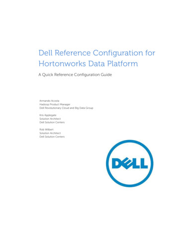
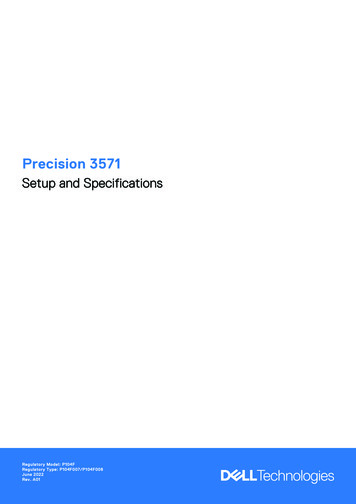
Architecture Overview - Dell Solutions for Oracle 11g on RedHat Enterprise Linux 5.1 and Oracle Enterprise Linux 5.1The Dell Reference Configuration for Oracle 11g on Red Hat Enterprise Linux 5.1 and Oracle EnterpriseLinux 5.1 is intended to validate the following solution components: Two node cluster comprised of Dell PowerEdge 2950 III quad-core servers.Dell/EMC CX3 Fibre-Channel storage system.Red Hat Enterprise Linux Release 5 Update 1Oracle Enterprise Linux Release 5 Update 1Oracle Database 11g R1 Enterprise Edition (11.1.0.6) x86 64.An architectural overview of the Dell Solution for Oracle 11g on Red Hat Enterprise Linux 5.1 and OracleEnterprise Linux 5.1 is shown in Figure 1 below. The architectures are made of the following components:Red Hat Enterprise Linux 5.1 Architecture: Dell Optiplex desktop systems that will access data stored within the Oracle databaseClient-server network made up of network controllers, cables and switchesDell PowerEdge 2950 III servers running RHEL5.1 and Oracle 11g R1 RAC (11.1.0.6)Dell/EMC CX3-10, CX3-20, CX3-40, and CX3-80 storage arraysRedundant Brocade Fibre Channel switches for a SAN environmentOracle Enterprise Linux 5.1 Architecture: Optiplex desktop that will access data stored within the Oracle databaseClient-server network made up of network controllers, cables and switchesDell PowerEdge 2970 III servers running OEL 5.1 and Oracle 11g R1 RAC (11.1.0.6)Dell/EMC CX3-10, CX3-20, CX3-40, and CX3-80 storage arraysRedundant Brocade Fibre Channel switches for a SAN environmentFigure 1 - Architectural Overview of Oracle on RHEL 5.1 OR OEL 5.1 with Dell/EMC StorageDell Reference Configuration for Oracle 11g R1 on Red Hat Enterprise Linux 5.1 and Oracle EnterpriseLinux 5.15
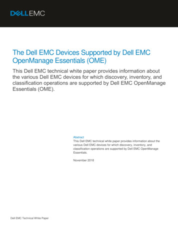
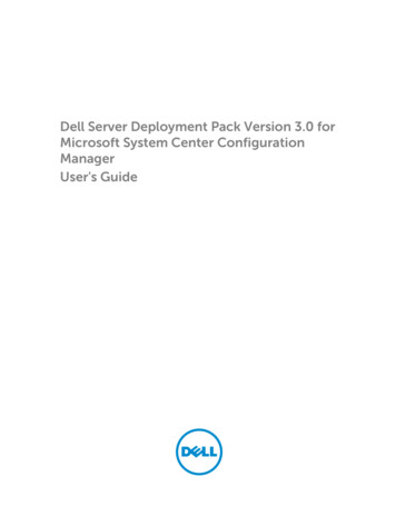
Hardware ConfigurationStorage ConfigurationConfiguring Dell/EMC CX3 Fibre Channel Storage Connections with DualHBAs and Dual Fibre Channel SwitchesFigure 2 illustrates the storage cabling of the two-node PowerEdge cluster hosting Oracle database and theDell/EMC CX3 storage array where the data resides. Each CX3 storage array has two storage processors(SP), called SPA and SPB, which can access all of the disks in the system. The CX3 storage array providesthe physical storage capacity for the Oracle 11g RAC database. Before data can be stored, the CX3physical disks must be configured into components, known as RAID groups and LUNs. A RAID group isa set of physical disks that are logically grouped together. Each RAID group can be divided into one ormore LUNs, which are logical entities that the server uses to store data. The RAID level of a RAID groupis determined when binding the first LUN within the RAID group. It is recommended to bind one LUN per1RAID group for database workloads to avoid disk spindle contention. For details on LUN configuration,please refer to the “Configuring Disk Groups and LUNs” section below.In the CX3 array, the LUNs are assigned to and accessed by the Oracle 11g cluster nodes directly throughone storage processor. In the event of a storage processor port failure, traffic will be routed to another porton the same SP if the host is connected to more than one SP port and the EMC PowerPath multi pathsoftware is used. In the event of a storage processor failure, LUNs on the failed processor will trespass tothe remaining storage processor. Both events could result in an interrupted service unless multiple I/Opaths are configured between the Oracle 11g RAC database hosts and the CX3 array. Therefore, it iscrucial to eliminate any single point of failures within the I/O path.At the interconnect level, it is recommended that each node of the Oracle 11g RAC have two HBAs withindependent paths to both storage processors. With the EMC PowerPath software installed on the clusternode, I/O can be balanced across HBAs as well. It is also recommended that two Fibre Channel switchesare used because in the event of a switch failure in a single Fibre Channel switch fabric environment, allhosts will lose access to the storage until the switch is physically replaced and the configuration restored.Figure 2 - Cabling a Direct Attached Dell/EMC CX3-801“Designing and Optimizing Dell/EMC SAN Configurations Part 1”, Arrian Mehis and Scott Stanford,Dell Power Solutions, June 2004. 022.pdfDell Reference Configuration for Oracle 11g R1 on Red Hat Enterprise Linux 5.1 and Oracle EnterpriseLinux 5.16
Figure 3 illustrates the interconnection of a PowerEdge server hosting Oracle 11g RAC and Dell/EMCCX3-80 storage system where the database resides in a SAN environment. This topology introduces a fibrechannel switch which provides the means to connect multiple storage subsystems to the host system withlimited HBA ports. With the addition of the fibre channel switch additional I/O paths are introduced,which can provide additional redundancy. By using two host bus adapters (HBA) in an Active/Activeconfiguration, commands and data can flow over both HBAs and fibre links between the server and storagesystem. If an HBA controller, switch, or a CX3-80 storage controller fails, operations continue using theremaining HBA – switch – CX3-80 storage controller combination.Figure 3 - Cabling a Dell/EMC CX3-80 in a SAN configurationNote: The different colored connections in Figure 3 are fibre channel connections. The different colorsfrom the Switches to the SPs represent different path options available from switches to the storage.Configuring Disk Groups and LUNsBefore application data can be stored, the physical storage must be configured into components known asdisk groups and LUNs. A LUN is a logical unit of physical disks presented to the host in the CX3 storage.Each disk group created provides the overall capacity needed to create one or more LUNs, which arelogical entities that the server uses to store data.Oracle Automatic Storage Management (ASM) is a feature of Oracle Database 11g which provides avertical integration of the file system and volume manager specifically built for the Oracle database files.ASM distributes I/O load across all available resource to optimize performance while removing the needfor manual I/O tuning such as spreading out the database files to avoid “hotspots.” ASM helps DBAsmanage a dynamic database environment by allowing them to grow the database size without having toshutdown the database to adjust the storage allocation.2The storage for an Oracle 11g RAC database can be divided into three areas of the shared storage. All ofthese storage areas will be created as block devices which are managed directly by Oracle clusterware orOracle Automatic Storage Management (ASM) instances, bypassing the host operating system.2“Oracle Database 10g – Automatic Storage Management Overview”, Oracle manageability/database/pdf/asmov.pdfDell Reference Configuration for Oracle 11g R1 on Red Hat Enterprise Linux 5.1 and Oracle EnterpriseLinux 5.17
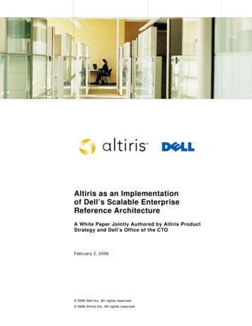
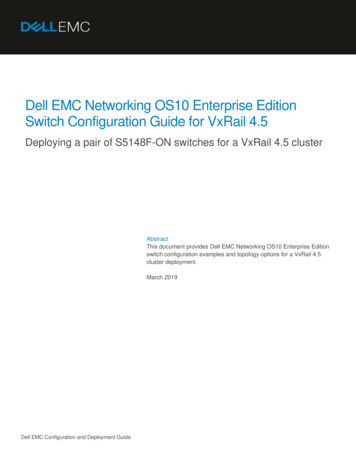
The first area of the shared storage is for the Oracle Cluster Registry (OCR), the Clusterware ClusterSynchronization Services (CSS) Voting Disk, and the Server Parameter File (SPFILE) for the OracleAutomatic Storage Management (ASM) instances. The OCR stores the details of the clusterconfiguration including the names and current status of the database, associated instances, services,and node applications such as the listener process. The CSS Voting Disk is used to determine whichnodes are currently available within the cluster. The SPFILE for the ORACLE ASM instances is abinary file which stores the ASM parameter settings. Unlike traditional database files, these filesmentioned above cannot be placed on the disks managed by ASM because they need to be accessiblebefore the ASM instance starts. These files can be placed on block devices or RAW devices that are3shared by all the RAC nodes. . If the shared storage used for the OCR and Votingdisk does notprovide external redundancy, it is a best practice to create two copies of the OCR and three copies ofvoting disk, configured in such a way that each copy does not share any hardware devices, avoiding4the creation of single points of failure. The second area of the shared storage is for the actual ORACLE database that is stored in the physicalfiles including the datafiles, online redo log files, control files, SPFILE for the database instances (notASM), and temp files for the temporary tablespaces. The LUN(s) on this area are used to create theASM diskgroup and managed by ASM instances. Although the minimal configuration is one LUN perASM diskgroup, multiple LUNs can be created for one ASM diskgroup and more than one ASMdiskgroups can be created for a database. The third area of the shared storage is for the Oracle Flash Recovery Area which is a storage locationfor all recovery-related files, as recommended by Oracle. The disk based database backup files are allstored in the Flash Recovery Area. The Flash Recovery Area is also the default location for allarchived redo log files. It is a best practice to place the databases data area and the flash recovery areaonto their separate LUNs that do not share any common physical disks this separation can enable4better I/O performance by ensuring that these files do not share the same physical disks.Table 1 shows a sample LUN configuration with LUNs for each of the three storage areas described above4in a best practice and alternative configuration .Figure 4 illustrates a sample disk group configuration on a Dell/EMC CX3-80 with two Disk ArrayEnclosure (DAE). There are separate partitions for the OCR, QUORUM, and SPFILE, data for userdefined databases, and flash recovery area on distinct physical disks. Spindles 0 through 4 in Housing 0 ofCX3-80 contain the operating system for the storage. These spindles are also used during power outage tostore the system cache data. It is not recommended to use the operating system spindles for as data or flashrecovery area drives. As the need for the storage increases additional DAE can be added to the storagesubsystem. With the use of Oracle Automated Storage Management (ASM), expansion of the DATA andthe Flash Recovery Area can be simple and quick.3“Oracle Clusterware 11g”, Oracle Technical docs/clusterware-11g-whitepaper.pdf4Oracle Clusterware Installation Guide for Linux, Oracle 11g document, B28263-03http://download.oracle.com/docs/cd/B28359 01/install.111/b28263.pdfDell Reference Configuration for Oracle 11g R1 on Red Hat Enterprise Linux 5.1 and Oracle EnterpriseLinux 5.18
LUNFirst AreaLUN(Best Practice)First AreaLUN(Alternative)MinimumSize1024 MBRAID10, or 12048 MBNumber ofPartitionsthree of 300MB each ifRAID 10 or1 used [6]Used ForOS MappingVoting disk,Oracle ClusterRegistry (OCR)SPFILE forASM instancesThree raw devices:1 x Votingdisk,1 x OCR,1 x SPFILE if RAID 10 or 1usedSix raw devices:3 x mirroredVoting disk on different disks2 x mirrored OCR on differentdisks1 x SPFILE if no RAID10 or 1 usedSix of 300MB each ifno RAID 10or 1 usedSecond AreaLUN(s)Larger10, or 5OneDatathan thefor readsize ofonlyyourdatabaseThird AreaMinimum10, or 5OneFlash RecoveryLUN(s)twice theAreasize ofyoursecondAreaLUN(s)Table 1 - LUNs for the Cluster Storage Groups / RAID GroupsData( LUN2)RAID 10(4 Spindles)Flash Recovery Area( LUN1) RAID 5ASM disk groupDATABASEDGASM disk groupFLASHBACKDGFlash Recovery Area(LUN2), RAID 5HotSpareDisk ArrayEnclosure 1Disk ArrayEnclosure 0CX OSSpindles(0-4)OCRVoting DiskSPFILERAID 10(2 Spindles)Data( LUN1)RAID 10(4 Spindles)HotSpareFigure 4 - Separation of Disk Groups and LUNs within a Dell/EMC CX 3-80 Storage ArrayDell Reference Configuration for Oracle 11g R1 on Red Hat Enterprise Linux 5.1 and Oracle EnterpriseLinux 5.19
RAID 10 is considered the optimal choice for Oracle 11g RAC LUN implementation because it offers faulttolerance, greater read performance, and greater write performance. 5 The disk group / RAID group onwhich the data is allocated should be configured with RAID 10.Because additional drives are required to implement RAID 10, it may not be the preferred choice for allapplications. In these cases, RAID 1 can be used for the OCR, Voting Disk, and SPFILE, which providesprotection from drive hardware failure. However, RAID 0 should never be considered as an option as thisconfiguration does not provide any fault tolerance. For the disk group / RAID group of the LUN for thedata storage area, RAID 5 provides a cost effective alternative especially for predominantly read-onlyworkloads such as a data warehouse database. Since the Flash Recovery Area is recommended as 2 timesof size of Data, if the space becomes an issue, RAID5 can be used for Flash Recovery Area. However,RAID 5 is not suitable for data for the database with heavy write workloads, such as in an OLTP database,as RAID 5 can have significantly lower write performance due to the additional read and write operationsthat come with the parity blocks on top of the load generated by the database.From the example above: 2 spindles are the minimal number of disks to form a RAID1 to ensure the physical redundancy. Initially we allocate two RAID 10 LUNs of 4 disks each for data, and two RAID 5 LUNs of 5disks each for the Flash Recovery. Then we use 4 disks for data LUN in RAID 10 and 5 disks for Flash Recovery LUN in RAID 5 asa unit or a building block to add more storage as the database grows in future.Each LUN created in storage will be presented to all the Oracle 11g RAC hosts and configured at the OSlevel. For details on the shared storage configuration at the OS level, please refer to the “ConfiguringShared Storage for the Oracle Clusterware using the RAW Devices Interface” section and the “ConfiguringShared Storage for the Database using the ASM Library Driver” section below.Server ConfigurationEach of the Oracle 11g RAC database cluster nodes should be architected in a highly available manner. Thefollowing sections will detail how to setup the Ethernet interfaces, the Fibre Channel host bus adapters(HBAs). These are the two fabrics that the database uses to communicate with each other and to thestorage. Ensuring that these interfaces are fault tolerant will help increase the availability of the overallsystem.Configuring Fully Redundant Ethernet InterconnectsEach Oracle 11g RAC database server needs at least three network interface cards (NICs): one NIC for theexternal interface and two NICs for the private interconnect network. The servers in an Oracle 11g RACare bound together using cluster management software called Oracle Clusterware which enables the serversto work together as a single entity. Servers in the cluster communicate and monitor cluster status using adedicated private network also known as the cluster interconnect or private interconnect. One of theservers in the RAC cluster is always designated as the master node.In the event of a private interconnect failure in a single interconnect NIC environment, the servercommunication to the master node is lost, and the master node will initiate recovery of the failed databaseinstance on the server.In the event of a network switch failure in a single private network switch environment, a similar scenariowill occur, resulting in a failure of every single node in the cluster except for the designated master node.5“Pro Oracle Database 11g RAC on Linux”, Julian Dyke and Steve Shaw, Apress, 2006.Dell Reference Configuration for Oracle 11g R1 on Red Hat Enterprise Linux 5.1 and Oracle EnterpriseLinux 5.110
The master node will then proceed to recover all of the failed instances in the cluster before providing aservice from a single node which will result in a significant reduction in the level of service and availablecapacity.Therefore, it is recommended to implement a fully redundant interconnect network configuration, with6redundant private NICs on each server and redundant private network switches.Figure 5 illustrates the CAT 5E/6 Ethernet cabling of a fully redundant interconnect network configurationof a two-node PowerEdge RAC cluster, with two private NICs on each server, and two private networkswitches. For this type of redundancy to operate successfully, it requires the implementation of the LinkAggregation Group, where one or more links are provided between the switches themselves. These twoprivate interconnect network connections work independent from the public network connection.To implement a fully redundant interconnect configuration requires the implementation of NIC teamingsoftware at the operating system level. This software operates at the network driver level to provide two7physical network interfaces to operate underneath a single IP address. For details on configuring NICteaming, please refer to the “Configuring the Private NIC teaming” section below.Figure 5 - Ethernet Cabling a Fully Redundant Private Interconnect NetworkConfiguring Dual HBAs for Dell/EMC CX3 storageAs illustrated in Figure 2 and Figure 3, it is recommended that two HBAs be installed on each of thePowerEdge server hosting the Oracle 11g RAC database because in the event of a HBA failure in a singleHBA fabric environment, the host will lose access to the storage until the failed HBA is physicallyreplaced. Using dual HBAs provides redundant links to the CX3 storage array. If the dual port HBAs isrequired to achieve the IO throughput, use two dual port HBAs connecting to two switches respectively toprovide redundant links.Software ConfigurationOperating System ConfigurationConfiguring the Private NIC TeamingAs mentioned in the Section “Configuring Fully Redundant Ethernet Interconnects” above, it isrecommended to install two physical private NICs (the onboard NICs can serve this purpose) on each of the6Dyke and Shaw, op. cit.Dyke and Shaw, op. cit.Dell Reference Configuration for Oracle 11g R1 on Red Hat Enterprise Linux 5.1 and Oracle EnterpriseLinux 5.1117
Oracle 11g RAC cluster servers to help guard against private network communication failures. In additionto installing the two NICs, it is required to use NIC teaming software to bond the two private networkinterfaces together to operate under a single IP address. Both Intel NIC teaming software and Broadcom NIC teaming software are supported. The NIC teaming software provides failover functionality. If a failureoccurs, affecting one of the NIC interfaces – examples include switch port failure, cable disconnection, orfailures of the NIC itself – network traffic is routed to the remaining operable NIC interface. Failoveroccurs transparent to the Oracle 11g RAC database with no network communication interruption orchanges to the private IP address.Configuring the Same Public Network Interface Name on All NodesIt is important to ensure that all nodes within an Oracle 11g RAC cluster have the same network interfacename for the public interface. For example, if “eth0” is configured as the public interface on the first node,then “eth0” should also be selected as the public interface on all of the other nodes. This is required for thecorrect operation of the Virtual IP (VIP) addresses configured during the Oracle Clusterware software8installation. For the purpose of installation, the public IP configured for the RAC node has to be aroutable IP. They cannot be 192.xxx.xxx.xxx, 172.xxx.xxx.xxx, or 10.xxxx.xxx.xxx. However, thisconfiguration can be changed post Oracle RAC installation.Configuring SSHDuring the installation of Oracle 11g RAC software, the Oracle Universal Installer (OUI) is initiated on oneof the node of the RAC cluster. OUI operates by copying files to and running commands on the otherservers in the cluster (is this before or after RAC is installed on the other nodes). In order to allow OUI toperform properly, the secure shell (SSH) must first be configured, so no prompts or warnings are receivedwhen connecting between SSH hosts as the oracle user. To prevent unauthorized users from accessing thesystems, it is recommended that RSH be disabled after the Oracle software installation.Configuring Shared Storage for the Oracle Clusterware using the RAW Devices InterfaceBefore installing Oracle 11g RAC Clusterware software, it is necessary for shared storage to be availableon all cluster nodes to create the Oracle Cluster Registry (OCR) and the Clusterware ClusterSynchronization Services (CSS) Voting Disks. The OCR file and the CSS Voting disk file can be placedon a shared raw device file. As discussed in the Section “Configuring Disk Groups and LUNs” above, twoLUNs are created for the OCR and three LUNS are created for Voting Disk, along with a SPFILE for theASM instances. These LUNs should be configured as raw disk devices.Support for raw devices has been deprecated in the Linux kernel 2.6 for Red Hat Enterprise Linux 5 andOracle Enterprise Linux 5. Earlier versions Linux like RHEL 4 or OEL 4 allowed access RAW devices bybinding the block device or partition to a character-mode device node such as /dev/raw/raw1. With therelease of OEL5 and RHEL5, this technique is no longer supported. Raw device binding cannot be createdusing /etc/sysconfig
Oracle Enterprise Linux Release 5 Update 1 Oracle Database 11g R1 Enterprise Edition (11.1.0.6) x86_64. An architectural overview of the Dell Solution for Oracle 11g on Red Hat Enterprise Linux 5.1 and Oracle Enterprise Linux 5.1 is shown in Figure 1 below. The architectures are made of the following components: