Transcription
Pobrane z czasopisma Annales AI- Informatica http://ai.annales.umcs.plData: 04/08/2020 20:55:19Annales UMCS Informatica AI 2 (2004) 143-151Annales UMCSInformaticaLublin-PoloniaSectio l and topological methods of fault tolerance assuranceMirosław Hajder, Paweł Dymora*Department of Distributed Systems, Faculty of Electrical and Computer Engineering,Rzeszów University of Technology, Wincentego Pola 2, 35-959 RzeszówAbstractMSpecial interest in designing, constructing and exploitation of fault tolerant systems isconnected with the need of attending to critical infrastructure systems. In this paper we focus onpresentation and analysis of the requirements demanded on the context of fault tolerance assurancein the critical infrastructure systems. Especially, we take into consideration algorithmical andtopological methods of fault tolerance assurance.U1. IntroductionIn term of fault tolerant systems we describe these computer systems, amongothers, which despite faults in their hardware or software module still preservetheir abilities to function in the whole or limited range. Problems of improperfunctioning includes the three main terms: failure, fault and error. Failure refersto an occurrence of the system of physical module damages. Fault is a conditionexisting in a hardware or software module that may lead to the failure of themodule. Error is an incorrect response from hardware or software modulecaused by the existence of faults [1].Faults may occur on different designing or exploitation levels. The highestlevel on which possible functioning faults may arise is the specification levelwhen as a result of the designer’s mistake during system designing an improperalgorithmical, architectural or structural solutions were used. The next level onwhich possible faults may occur is the level of specifications realization. Thesefaults are related with improper implementation of earlier worked outspecification on hardware or software system modules. Another level of thefaults occurrence is the production and exploitation level on which failure of oneor a few system modules can take place mostly as a result of not obeying thespecification and exploitation parameters. Obviously faults may also occur as aresult of outer factors such as radiation, electromagnetic field or operatormistakes.*Corresponding author: e-mail address: dymorap@prz.rzeszow.pl
Pobrane z czasopisma Annales AI- Informatica http://ai.annales.umcs.plData: 04/08/2020 20:55:19144Mirosław Hajder, Paweł DymoraUMCSFrom the activities point of view whose aim is to minimize the damagingeffects to the system functioning we can distinguish three fundamentallydifferent approaches. Fault avoidance is based on supplying the system with theelements allowing, on the basis of the functioning results, analysis and systemmodules diagnosis to counteract arising of potential functioning errors. Faultmasking is based on excluding system elements which are the source of errors.Fault tolerance is the system ability to continue computations in the faultysystem. Fault tolerance can take advantage of fault masking as well as systemreconfiguration [2].In our work we consider only the topology reliability. The main requirementsfor fault tolerant topology can be formulated as follows:1. Topology should ensure the required level of fault tolerance without anyexcessive increase of its realization costs.2. Topology should ensure the ability to decentralize the system diagnosticmethods using relatively simple means.3. Topology should ensure the ability of simple routing of sent informationwith the mineralized level of hardware support.From the topological point of view the topology designing procedure reducesto the assurance of minimal product value of diameter and designed topologydegree. In other words, parameters characterizing the topology fault toleranceare their survivability and cohesion.In this paper we focus not so much on designing procedures of fault tolerantsystems as on the methods and means of system reconfiguration in order topreserve qualitative and quantitative system characteristics.2. The critical infrastructure systems, and fault toleranceThe limited level of survivability and cohesion characterizes all contemporarycomputer systems. It results from the fact that each of currently used systemelements or programs may yield to a fault as a result of improper use, mistakesmade in a designing procedure wear out, etc. The elements of computer structureare duplicated in time, hardware and information in order to eliminate orminimize the effects of the faults occurrence. In this way, fault tolerantstructures come into being which in the case of faults occurrence makes thatstructure preserves its functions in the whole or limited range.Among the computer systems we can distinguish a varied failure treatment.On the one hand, there exists systems in which limited realization of systemfunctions for example in the efficiency range does not make using of itsresources difficult. But there exists the whole group of systems in whichdetermination of the efficiency parameters in particular limitation of systemfunctions is unacceptable. The management systems of electric power networks,air or railway transportation are an example of such systems. Such systems areoften called critical infrastructure systems. Special interest in designing,
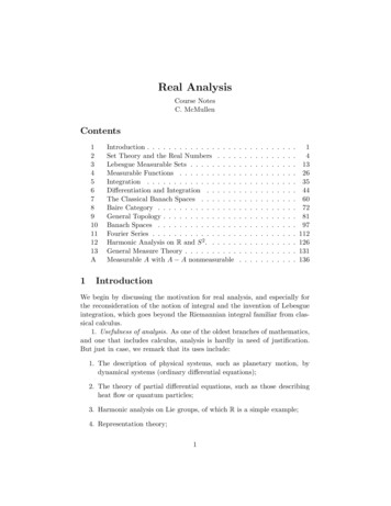
Pobrane z czasopisma Annales AI- Informatica http://ai.annales.umcs.plData: 04/08/2020 20:55:19Algorithmical and topological methods of fault tolerance assurance145UMCSconstructing and exploitation of fault tolerant systems is connected with a needof attending to critical infrastructure systems [3,4].As mentioned above the critical infrastructure system should be characterizedby specific features which guarantees its fault tolerance in the case of possiblefailure. In particular in the range of executed functions the system architecture isa derivative of requirements demanded from them. Let us think over whatfeatures critical infrastructure system should be characterized by. The analysis isbegun with the topological parameters.The basic principle of the critical infrastructure system functioning is themaximal availability assurance of system resources. For this reason applying theshared medium topology is considered to be questionable. Certainly a bettersolution would be to apply the direct topologies which guarantee dedicatedcharacter of connects. In particular, in these systems point to point connectionscan be applied because of traffic routing requirement elimination. Such networksare not fault tolerant because it is impossible to set alternative connection linksin it. The recommended feature of topological structures in the fault tolerantsystems is preservation of all system topological characteristics besides adiameter. But let us notice that as a result of this system class complexity,especially of the significant number of nodes it is hardly possible to fulfill theabove constraint. The topologies of critical infrastructure systems in principleare neither symmetric nor regular topologies. Besides, for of the security reasonsthey exclude the need of excessive topology development in order to make itsymmetric. Other important features of the critical infrastructure systems arehardware and software heterogeneity and also data distribution. Heterogeneity isbased on realization of varied functions by the nodes implemented with thevaried architecture hardware thereby varied capabilities. The data distributionfeature is related with the distributed data processing. Data are often gatheredand shared with the other users directly from the place of their rise. Thus, it isnecessary to ensure the efficient nodes co-operation in both the mutual datasharing process and its processing [4].Mutual relationships between the selected features of the criticalinfrastructure systems are shown in Fig. 1.SystemtopologySystemefficiencyHardware and softwareheterogeneityDatadistributionFig. 1. Relationships between the features of the critical infrastructure systems
Pobrane z czasopisma Annales AI- Informatica http://ai.annales.umcs.plData: 04/08/2020 20:55:19146Mirosław Hajder, Paweł DymoraUMCS3. Reconfiguration as an instrument of preserving fault toleranceReconfiguration is one of basic methods of fault tolerance ensuring in thecritical infrastructure systems. A special attention was arouse by reconfigurationalgorithms in the context of distributed computation systems in which asignificant computation power is achieved by connecting a lot of independentprocessing units. In most of these systems in order to ensure their fault tolerancethe method is used which allows to apply additional processing units whose aimis to take over computation functions from the faulty node.If we assume that in the case of occurrence of processing element failure thenumber of computed tasks in a system would be invariable, then it can turn outthat critical resource of the system is an operating memory. Due to that fact thereconfiguration algorithms can be classified from the essential memory sizepoint of view that is necessary to continue computation. On the one hand we candistinguish algorithms demanding invariableness of the whole system memorysize but on the other hand, there exist algorithms which demand only memorysize invariableness of faulty processing element or its neighbor processingelements. Other classification is based on specifying changes degree whichoccur directly after failure. In order to ensure the maximally fast systemreconfiguration it is necessary to minimize the number of changes introduced tothe system in case of failure occurrence. The above changes concern both theinterconnection topology and tasks assigned to particular processing elements. Inorder to ensure the presented requirements usually the methods requiring onlylocal reconfiguration are applied. In this case only faulty node and nodes directlyneighboring with it would be subordinate to appropriate reconfiguration. But inpractice such a method may turn out to be too expensive in application. Due tothat fact in reconfigurations the idea which is based on the assumption thatprocessing elements are gathered in groups to which spare elements are added isapplied. To increase the universality of presented method it is assumed that spareelements would serve not only the group (cluster) for which they were assignedbut also neighbor processor clusters. On the one hand, such a solution guaranteesthe increase of system reconfiguration speed. On the other hand, it causes thedecrease of reconfiguration flexibility thereby limits operating reliability of thewhole system.In the light of presented considerations, the reconfiguration algorithms maybe classified into two groups: local algorithms and global algorithms. In the caseof local algorithms at the expense of redundancy the maximized reconfigurationspeed is achieved. Global algorithms guarantee a redundancy optimization that isachieved at the expense of reconfiguration range and the realization time.In order to realize the presented reconfiguration it is required to apply thesystem architecture with redundancy. We classify the system elements intoprimary elements and spare elements. In the case of primary element failure thiselement is replaced with the spare element.
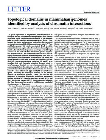
Pobrane z czasopisma Annales AI- Informatica http://ai.annales.umcs.plData: 04/08/2020 20:55:19Algorithmical and topological methods of fault tolerance assurance147MCSLet us consider the example of system with cluster organization including theset of spare elements with hypercube interconnections.It is assumed that the computation system is organized in the form of clusters.Each of them has a form of hypercube additionally equipped with redundantelements. Fig. 2 shows the structure in which except for 16 primary elementsconnected into four-dimensional hypercube, it uses 8 spare elements. Theconnection method of primary elements with the spare ones is presented inFig. 2b.UFig. 2. Expanded four-dimensional hypercubeEach of the primary system elements may be denoted as (i, j ) , where1 i, j 4 . The spare nodes may be denoted as (0, j ) , where 1 j 4 or(i ,0) , 1 i 4 . In this way fault tolerant cluster – FTBB (Fault Tolerant BasicBlock) was constructed. This FTBB cluster consists of 24 elements where eachprimary node (i, j ) might be replaced with one of two spare nodes (0, j ) or(i,0) . Now, let us focus on reconfiguration realized in the FTBB cluster.In the FTBB system there is a possibility of such a system failure that thewhole system would be out of order. It takes place when none of the spareelements (0, j ) or (i,0) would be able to replace the faulty node (i, j ) .Regardless of the system reconfiguration type (local, global) the faulty nodemust be replaced with the elements from the FTBB cluster. For example, if thenode (i, j ) fails in the first place one should try to replace such a node with thenode (i,0) . If the node (i,0) is unavailable it should be replaced (if possible)with the node (0, j ) . The realization order of the replacing (reconfiguration) isfree. But it is advisable to work out a certain replacing method. For example, ifi j replacement might begin with the node (i,0) or with the node (0, j ) . Thissolution guarantees the optimization of both available spare element
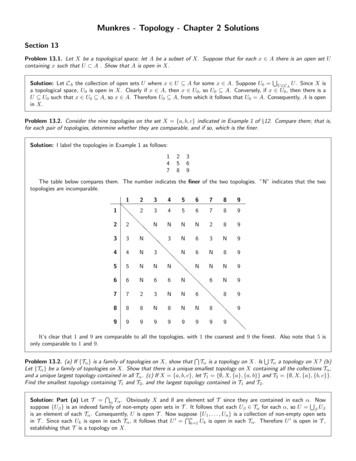
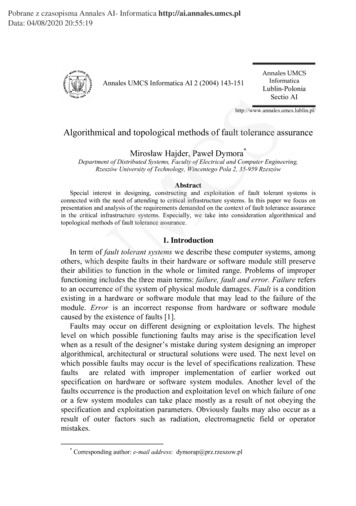
Pobrane z czasopisma Annales AI- Informatica http://ai.annales.umcs.plData: 04/08/2020 20:55:19Mirosław Hajder, Paweł CSorganizations (column, row). Besides it is characterized by significant speed. Inorder to explain the presented reasoning let us consider the following example.Let us assume that Fig. 3 shows structure where the following nodes (2,1),(2,2), (3,3), (1,2) and (4,2) failed. The failures followed the presented order. Ifthe discussed above reconfiguration method is used then reconfiguration schemewould look like the presented one in Fig. 3a. It is not difficult to notice that fournodes in the case of new failure would not be able to be replaced with the spareelements. These nodes are represented in Fig. 3 by double circles. These nodesare (1,1), (1,3), (4,1) and )(4,4)(a)(b)UFig. 3. Local (a) and global (b) reconfigurationsApplying the global reconfiguration may give the results shown in Fig. 3b. Inthis case only failure of the node (3,2) would not be repairable. Reconfigurationmay also be used for other topologies like e.g. mesh, torus. It is also acceptableto use a much more modest set of redundant elements. Now, let us consider thecase shown in Fig. 4.Fig. 4a shows the graph G representing a distributed system based on the 3 x3 torus topology T3,3 . For a subset Z of V (G ) let G ( Z ) denote the subgraphinduced in G by the nodes in Z . Let NG (u ) denote the set of neighbors of anode u in G . For example in Fig. 4a, N G (9) {3,6,7,8} where G is the 3 x 3torus topology T3,3 . If F is the set of faulty nodes in G , then G F denotesthe graph obtained by deleting the nodes and all edges incident on them from G .Fig. 4b shows the graph T3,3 {5,9} obtained when nodes 5 and 9 become faulty.We consider only the node failures. Faulty edges can be modeled as faults in thenodes on which these edges were incidental.
Pobrane z czasopisma Annales AI- Informatica http://ai.annales.umcs.plData: 04/08/2020 20:55:19149UMCSAlgorithmical and topological methods of fault tolerance assuranceFig. 4. Reconfiguration around faults in the torus topologywith the restricted set of redundant elementsA supergraph G '[k , G ] of G is a k -fault tolerant realization of G, if for anyset F of k nodes of G’, G ' F contain a subgraph isomorphic to G. Fig. 4cshows an example of a 2 -fault tolerant supergraph G '[2, T3,3 ] of T3,3 presentedin Fig. 4a obtained by inserting the redundant nodes r1and r2, and the redundantlinks. The 2 -fault tolerant supergraph of Fig. 4c is obtained by a construction inwhich the redundant nodes are connected to all the nodes of T3,3 and to oneanother. The reconfiguration of this 2 -fault tolerant supergraph around faultynodes 5 and 9 is shown in Fig. 4d, where the redundant nodes r1 and r2 directlyreplace nodes 5 and 9, respectively.An alternative to constructing k-fault tolerant supergraphs is to partition thenode set of G into subsets V1 ,.,Vt , introduce disjoint sets of ki redundant nodesin each Vi to make the induced subgraph G (Vi ) the ki -fault tolerant realization.Such a supergraph of G is denoted by G '[{k1 , k2 ,., kt }, G ] and is said to be a{k1 , k2 ,., kt } fault tolerant realization of G [5].
Pobrane z czasopisma Annales AI- Informatica http://ai.annales.umcs.plData: 04/08/2020 20:55:19150Mirosław Hajder, Paweł DymoraCS4. Reconfiguration algorithmThe basics of the reconfiguration process is the mapping of faulty nodes of Gonto those fault free including those redundant of G’. The new node labels underthis mapping determine a fault free copy of G. In such a mapping from V (G ) toV (G ') if node v is mapped to a node u the neighbors of v in G have to bemapped to a subset of the neighbors of u in G’. Such a mapping in G’ is called aG-mapping. In the reconfiguratin method we designate a small subset Zν ofnodes of G’ to which v can be mapped for reconfiguring around faults. Eachnode u in Zν is called a node mapper of v denoted by M u (v) and Zν theMmapping set of v denoted by mapp (v ) . A mapping graph H (G) of a graph G isa directed graph whose node set consists of all the nodes of G and someredundant nodes, and whose edge set is {(u , v) : v V (G ), u mapp (v)} . A kmapping graph is the one whose implied supergraph is k-fault tolerant. Amapping set for a node v of G in H (G) is an ordered set (v1 ,., vh ) of nodes inV ( H (G )) , such that M v1 (v) , M v j (v j 1 ) , for 1 j h and vh is the onlyredundant node in this ordered set. A mapping set for a subset Z of V (G ) is a setof disjoint mapping sets for each node in Z , none of which contains any node ofZ.US ta rtM a p p : F ;D e n o te a ll n o d e s in F a s u n a v a ila b le In itia liza tio n o f th e m a p p in g s e t fo r e a c hfa u lty n o d ex FM a p p se t(x ): 0NOu FL e t u b e th e n o d e in M a p pYESL e t w b e th e a v a ila b le m a p p e r o f uF a u lt(w ): uF a u lt(w ): F a u lt(u )F a u lt(w ) in d ic a te s th e fa u lty n o d ew h o s e m a p p in g s e t w b e lo n g s toM a p p s e t(F a u lt(x )): M a p p s e t(F a u lt(u )) wIn se rt w m a p p in g s e t o f th ea p p ro p ria te n o d e (F a u lt(w )) in FD e n o te w a s u n a v a ila b lea n d re m o v e u fro m M a p pwis a n a c tiv enodeYESM a p p : M a p p {w }NOYESM app 0NO x FM a p p s e t(x)S to pFig. 5. An algorithm that finds mapping set for the fault set F in the mapping graph H (G )
Pobrane z czasopisma Annales AI- Informatica http://ai.annales.umcs.plData: 04/08/2020 20:55:19Algorithmical and topological methods of fault tolerance assurance151CSThe presented mapping set for v specifies a G-mapping which can be performedwhen v is faulty, so that v is mapped to v1 which, in turn, is mapped to v2 , andso on, until vh 1 is mapped to the redundant node vh , thus configuring it into thenew nonfaulty system.An algorithm that finds mapping set for k or fewer faulty nodes is presentedin Fig. 5. This algorithm is based on the theorem which confirms that if eachnode of G is mapped exactly by k, the other nodes in the mapping graph H (G)of G, and H (G) are acyclic, then H (G) is k -mapping graph [5,6].UM5. ConclusionsIn the fault tolerant systems its accessibility is mainly achieved by thetopological parameters of the interconnection network optimization. Faulttolerance may be guaranteed by the reconfiguration of the existing resources sothat the basic system functional parameters would not change. In such a case thesystem efficiency is possible to get worsen.An alternative method is applying of the redundant elements which may beused in the reconfiguration process. The use of the large number of redundantelements causes the increase of the system fault tolerance without any systemcapacity degradation. However, such a situation results in a significant increaseof the system realization costs. In the other case when the lower number ofredundant elements is applied the system realization cost is lower but the systemcapacity degradation increases. Hence, applying of the optimal number of theredundant elements in the system reconfiguration process is an issue whosesolution allows to realize structures with the increased level of fault tolerance bythe relatively acceptable worsening of capacity parameters and increase of thecosts [7].The structure reconfiguration of the distributed critical infrastructure systemsshould be realized on the basis of the topologies characterized by the presentedtopological parameters especially regular and symmetric [1] Hajder M., Loutskii H., Stręciwilk W., Informatyka – Wirtualna podróż w świat systemówi sieci komputerowych, Wydawnictwo WSIiZ, Rzeszów, (2002), in Polish.[2] Pradhan D.K., Reddy S.M., A fault tolerant communication architectures for distributedsystems, IEEE Transactions on Computers, (31)(9).[3] Elder M.C., Fault tolerance in critical information systems, University of Virginia, (2001).[4] Hajder M., Mazurek M., Dymora P., Hajder L., Bezpieczeństwo systemów uszkadzalnych,Zeszyty Naukowe WSIiZ w Rzeszowie, Rzeszów, (2001), in Polish.[5] Dutt S., Hayes J.P., Some practical issues in the design of fault tolerant multiprocessors,IEEE Transactions on Computers, 31(5).[6] Dolan A., Aldous J.M., Introduction to Networks and Algoritms, Wiley, (1993) 560.[7] Hajder M., Mazurek M., Dymora P., Virtual topologies of multinode wide networks, PoznańUniversity of Technology, Poznań, (2002), 197.
masking is based on excluding system elements which are the source of errors. Fault tolerance is the system ability to continue computations in the faulty system. Fault tolerance can take advantage of fault masking as well as system reconfiguration [2]. In our work we consider only the topology reliability. The main requirements