Transcription
Retrofitting Combined Spaceand Water Heating Systems:Laboratory TestsB. Schoenbauer, D. Bohac, P. Huelman,R. Olson, and M. HewettNorthernSTAROctober 2012
NOTICEThis report was prepared as an account of work sponsored by an agency of theUnited States government. Neither the United States government nor any agencythereof, nor any of their employees, subcontractors, or affiliated partners makes anywarranty, express or implied, or assumes any legal liability or responsibility for theaccuracy, completeness, or usefulness of any information, apparatus, product, orprocess disclosed, or represents that its use would not infringe privately owned rights.Reference herein to any specific commercial product, process, or service by tradename, trademark, manufacturer, or otherwise does not necessarily constitute or implyits endorsement, recommendation, or favoring by the United States government orany agency thereof. The views and opinions of authors expressed herein do notnecessarily state or reflect those of the United States government or any agencythereof.Available electronically at http://www.osti.gov/bridgeAvailable for a processing fee to U.S. Department of Energyand its contractors, in paper, from:U.S. Department of EnergyOffice of Scientific and Technical InformationP.O. Box 62Oak Ridge, TN 37831-0062phone: 865.576.8401fax: 865.576.5728email: mailto:reports@adonis.osti.govAvailable for sale to the public, in paper, from:U.S. Department of CommerceNational Technical Information Service5285 Port Royal RoadSpringfield, VA 22161phone: 800.553.6847fax: 703.605.6900email: orders@ntis.fedworld.govonline ordering: http://www.ntis.gov/ordering.htmPrinted on paper containing at least 50% wastepaper, including 20% postconsumer waste
Retrofitting Combined Space and Water Heating Systems:Laboratory TestsPrepared for:The National Renewable Energy LaboratoryOn behalf of the U.S. Department of Energy’s Building America ProgramOffice of Energy Efficiency and Renewable Energy15013 Denver West ParkwayGolden, CO 80401NREL Contract No. DE-AC36-08GO28308Prepared by:B. Schoenbauer, D. Bohac, P. Huelman,R. Olsen, and M. HewettNorthernSTAR Building America Partnership322 Kaufert Lab2004 Folwell AvenueSaint Paul, MN 55108NREL Technical Monitor: Stacey RothgebPrepared under Subcontract No. KNDJ-0-40338-00October 2012iii
AcknowledgmentsThis report was prepared for the U.S. Department of Energy Building America program. Fundingfor this work was provided by the National Renewable Energy Laboratory under contract KNDJ0-40338-00. Additional funds to support this work were provided by the WeatherizationAssistance Program through a Sustainable Energy Resources for Consumers grant, the Center forEnergy and Environment, and the Energy Conservatory. Additional support through loaned ordonated equipment was provided from Rinnai, A.O. Smith, American Water Heaters, Eternal,Heat Transfer Products, Navien America, Enerzone, Lifebreath, NuAire, and AdvancedDistributor Products.The primary authors were Ben Schoenbauer, Dave Bohac, and Martha Hewett, Center for Energyand Environment, and Jake McAlpine, Sustainable Resource Center.These authors would like to acknowledge the contributions and support of Becky Olson,Sustainable Resource Center, for project management and cost analysis; Pat Huelman,University of Minnesota, for expertise and role as an advisor to the project; Alex Haynor,Corinne Wichser, and Josh Novacheck, Center for Energy and Environment for work on fieldinstallations and data analysis; Anna Jursik, Center for Energy and Environment for reportediting; Gary Nelson, The Energy Conservatory for donating space for the laboratory and histime as an advisor; Gary Klein, Affiliated International Management, for his time and expertise;Louise Goldberg, University of Minnesota–BBE, for the BEopt modeling and analysis; and TomSchirber, University of Minnesota, for coordinating and editing reports.iv
ContentsAcknowledgments . ivList of Figures . viList of Tables . viiDefinitions . viiiExecutive Summary . ix1234567Introduction . ixExperiment . ixAnalysis. ixResults . ixConclusions . xiIntroduction . 11.1 Background .21.2 Relevance to Building America’s Goals .31.3 Cost Effectiveness .31.4 Tradeoffs and Other Benefits .41.5 The Role of Combi Systems in Low Income Weatherization .4Experiment . 52.1 Research Questions .52.2 Technical Approach .52.3 Measurements .62.4 Combi Equipment and Test Instrumentation .8Analysis . 123.1 Standby Loss and Steady-State Efficiency Analysis .123.2 Air Handler Capacity Analysis .133.3 Full System Analysis .133.4 Error Analysis .13Results . 154.1 Standby Loss .154.2 Steady-State Efficiency.184.3 Air Handler Capacity .194.4 Full System .234.4.1 Maximum Capacity.264.4.2 Response to Overlapping Events .274.4.3 Domestic Hot Water Supply Temperature .294.5 Installation Process and Specifications .32Discussion. 355.1 Air Handler Improvement .355.2 Heating Plant Improvement .35Conclusions . 37References . 38v
List of FiguresFigure 1. Energy consumption during standby mode operation at a set point of 140 F, exceptBoiler 2, which has a fixed internal hot water set point of 156 F . xFigure 2. Heating plant steady-state space heating efficiency over a range of return watertemperatures . xiFigure 3. Diagram of a combined space and water heating system . 1Figure 4. Test setup for the heating plant with a simulated AH . 7Figure 5. Test setup for the AH testing . 8Figure 6. Photos of test laboratory with combi system installations and venting terminations . 11Figure 7. Energy consumption during standby mode at a set point of 140 F . 16Figure 8. Infrared and visual images of Boiler 4 in standby operation . 16Figure 9. Infrared and visual images of TWH 1 in standby operation . 17Figure 10. Infrared and visual images of TWH 2 in standby operation . 17Figure 11. Heating plant steady-state efficiency over a range of return water temperatures . 18Figure 12. Heating plant steady-state efficiency for 60 kBtu/h heating load . 19Figure 13. AH7 performance mapping test of supply air temperature . 20Figure 14. AH7 performance mapping test of return water temperature . 21Figure 15. AH7 performance mapping test of space heating capacity . 21Figure 16. AH6 measured and manufacturer specified water temperature difference . 23Figure 17. Maximum capacity test profile for full system tests . 24Figure 18. DHW interrupt load profile for full system tests . 24Figure 19. Low use load profile for full system tests . 25Figure 20. Difference in supply temperature from the start to end of a two shower and spaceheating demand . 27Figure 21. DHW supply temperature response when space heating demand was initiated . 28Figure 22. DHW temperature changes before and after the mixing valve for TWH 1 . 29Figure 23. DHW supply temperature profile for a short 1.2-gpm draw . 30Figure 24. DHW supply temperature profile for TWH 2 . 31Figure 25. Typical outdoor setback temperature control curve . 34Figure 26. Typical combi system installation with a boiler . 36Unless otherwise indicated, all figures were created by NorthernSTAR.vi
List of TablesTable 1. Laboratory Instrumentation . 9Table 2. Laboratory Tested Combi Heating Plants . 9Table 3. Laboratory Tested Hydronic AHs . 10Table 4. Standby Site Energy Consumption at a Set Point Temperature of 140 F . 15Table 5. Sizing Chart for AHs for a 140 F Supply Water Temperature . 22Table 6. Full System Test Load Profiles (Btu/h). 25Table 7. DHW Draw Characteristics for the Low Use Load Profile . 29Table 8. DHW Performance of Combi Systems Under Small and/or Short Draw Conditions . 31Table 9. Combi System Sizing Chart . 33Unless otherwise indicated, all tables were created by NorthernSTAR.vii
DefinitionsAFUEAnnual fuel utilization efficiencyAHAir handlerBEopt Building Energy Optimization (software program)cfmCubic feet per minuteCombiCombined space and water heating systemDHWDomestic hot waterEFEnergy factorgpmGallons per minuteTWHTankless water heaterWHWater heaterviii
Executive SummaryIntroductionBetter insulation and tighter envelopes reduce space heating loads for new and existing homes.For many homes, decreased space heating loads enable a single heating plant to provide spaceand domestic water heating loads. These systems, called integrated appliances or combination(combi) systems, can also eliminate safety issues associated with natural draft appliances byusing one common sealed combustion vent.The research will use combi systems with water heater (WH) or boiler heating plants teamedwith forced air distribution space heating systems. In each house, the existing furnace will bereplaced with a hydronic air handler (AH) that includes an AH, a water coil, and a water pump tocirculate water between the heating plant and the coil. The tank type WH will be replaced byeither a WH or a boiler with a separate circuit for domestic hot water (DHW). Various optionsfor DHW priority, DHW tempering, and heating plant temperature set point control will beconsidered.ExperimentInitial bids indicated that local mechanical contractors had only limited experience in the designand installation of high efficiency combi systems. The NorthernSTAR combi laboratory wascreated to identify proper system components, designs, operating parameters, and installationprocedures to ensure field installed systems are highly efficient. The laboratory also provided aplace for contractors, utility representatives, weatherization agents, and codes officials to viewthe systems and become familiar with their installation. Nine heating plants were installed in thelaboratory space. Four condensing combi boilers with heating loops for space and domesticwater heating (Boiler 1, Boiler 2, Boiler 3, and Boiler 4) were tested Two (Boiler 2 and Boiler 4)had internal storage for hot water . Three condensing storage tank type WHs were installed(Tank 1, Tank 2, and Tank 3): one condensing tankless water heater (TWH 1) and a condensinghybrid WH that has a 199,000 Btu/h modulating burner and 2 gal of storage capacity (TWH 2).AnalysisLaboratory tests—heating plant standby mode energy use, space heating steady-state efficiency,AH capacity, and full system output capacity—were used to optimize combi system efficiency.Data loggers were used with water flow rate and water temperature differences to measuresystem energy output. Gas meters and electric watt transducers were used to measure energy andpower input at 1-s intervals. The data were then analyzed to determine the best operatingparameters and system components. Hydronic AH steady-state performance measurementsdetermined output capacities that provided acceptable return water and supply air temperatures.Heating plant capacity results were used to develop algorithms to determine whether a systemcould meet DHW and space heating loads. Combined space heating and DHW load profiles wereused to evaluate transient performance.ResultsStandby tests showed that some heating plants had much higher loss rates than others. Figure 1shows idle energy consumption at a set point of 140 F. Heating plants with no hot water storage(Boiler 1, Boiler 3, and TWH 1) had no gas use; the gas use for the units with storage variedfrom 29 to 103 therms/yr. The standby consumption of the three tank type WHs was about equalix
to or lower than that of the tankless water heater (TWH 2) and boilers with storage (Boiler 2 andBoiler 4). TWH 2, Boiler 2, and Boiler 4 had standby losses greater than desirable consideringthose units had notably smaller storage volumes than the tank type heaters. For these systems,the level of insulation appeared to have more effect than the storage size on idle losses.1400Energy Consumption During Stand by [Btu/hr]120010008006004002000Boiler 1Boiler 2(156)Boiler 3Boiler 4TWH 1GasTHW 2Tank 1Tank 2Tank 3ElectricFigure 1. Energy consumption during standby mode operation at a set point of 140 F,except Boiler 2, which has a fixed internal hot water set point of 156 FFigure 2 shows the steady-state efficiency of each heating plant for a range of return watertemperatures, 90 –120 F, which resulted in heating load of 20,000 to 100,000 Btu/h. (A set pointtemperature of 130 F and a flow rate of 4 gpm were used for all tests.) The heating plants hadsimilar steady-state efficiencies with a low of 86.1% for Boiler 3 and high of 90.6% for TWH 2.Given that the uncertainty of the efficiencies was 1.5 percentage points, the difference in steadystate efficiency was significant only for the highest and lowest efficiency systems. The averageefficiency of the four boilers was 1.8 percentage points lower than the average for the TWHs and1.9 percentage points lower than the tank type WH average. However, the difference in averageefficiency between the three system types was within the expected measurement error.x
100%Set Temp 130F, Flow 4Steady-State Space Heating Efficiency95%90%85%80%75%70TANK 180TANK 290TANK 3100Return Water Temperature, FBOIL 1BOIL 2BOIL 3110120BOIL 4TWH 1130TWH 2Figure 2. Heating plant steady-state space heating efficiency over a range ofreturn water temperaturesAH capacity testing determined the available heat output rate for each AH. AH capacity wasdetermined by requiring the water temperature leaving the AH to be 105 F. The delivered airtemperature was required to be 110 F to prevent occupant discomfort. These requirementsgreatly restricted the available capacities from those specified by the manufacturers.ConclusionsThe highest system efficiencies were achieved by minimizing the water temperatures returningfrom the hydronic AH. Heating loads were determined for each site. These loads were used toselect the water flow rates and airflow rates that would result in low return water temperaturesand meetg the necessary load with an acceptable air temperature. Laboratory tests showed thatthe heating plant steady-state efficiency decreased with increasing return water temperature. Thedecrease in efficiency became more significant as the return temperature increased above 110 F.Laboratory testing verified that systems were capable of meeting heating loads up to 50,000Btu/h with acceptable return water temperatures and supply air temperatures. These designsprovide steady-state space heating efficiencies 85%.System design and sizing information developed in the laboratory is currently being used tooptimize systems for the 300 site implementation project. The laboratory work has beeninvaluable to this process. The installers and program managers thus have confidence that thesesystems will meet the needs of the homeowners.xi
The performance of combi systems is limited by currently available equipment. Most hydronicAHs were not designed to produce lower return water temperatures necessary for combi systemswith a condensing heating plant. Several manufacturers, at least one in direct reaction to thefindings from this project, have begun to improve combi equipment. AHs with improved heattransfer performance will allow for lower and lower return water temperatures. Variable flowrate water pumps and fans, along with the necessary control capabilities, have significantpotential to provide a greater range in heating output and to provide low return watertemperatures. Also, the manufacturer required that the primary secondary loop configuration forcombi systems using boilers significantly increases return water temperatures, reducing systemefficiency. Modifications to this configuration could improve system efficiency as much as 10%.xii
1 IntroductionBetter insulation and tighter envelopes are reducing space heating loads for new and existinghomes. For many homes, decreased space heating loads enable a single heating plant to providespace and domestic water heating loads. These systems, called dual integrated appliances orcombination (combi) systems, can also eliminate safety issues associated with natural draftappliances because they use one common sealed combustion vent. Figure 3 shows a typicalcombi system set up, with a heating plant and a hydronic air handler (AH). During a hot waterdraw the heating plant operates like a water heater (WH): cold water comes into the storagevolume as hot water leaves (for units with storage). In systems without storage, cold water entersand is heated as necessary. During a space heating event, hot water leaves the heating plant,passes through the coil in the AH, and transfers heat into the airflow. The cooler water thenleaves the AH and flows back to the heating plant. The figure shows an open loop system wherepotable water is circulated to the AH for space heating. Closed loop systems use a heatexchanger between the heating loop in the heating plant and the AH.Cold Water MainsHot SpaceHeating AirDHW LoadsSupply to AHHeatingPlantReturn from AHHydronicAirHandlerFigure 3. Diagram of a combined space and water heating systemThe research will use combi systems with condensing WH or boiler heating plants teamed withforced air distribution space heating systems. In each house, the furnace will be replaced with ahydronic AH that includes an AH, water coil, and water pump to circulate water between theheating plant and the coil. The tank type WH will be replaced by either a WH or a boiler with aseparate circuit for domestic hot water (DHW). Various options for DHW priority, DHWtempering, and heating plant temperature set-point control will be considered.This project will use several types of condensing heating plants to characterize the installedperformance of combi systems. The primary objective will be to document energy savings, and1
the monitoring will include key system parameters such as return water temperature to betterunderstand variations from expected performance and identify improved system designs. Theproject will also determine the installation costs and potential cost reductions with , mechanical contractors have custom engineered and pieced together combi systemsin the field. They focused on assembling functional systems and had neither the time nor themeans to evaluate or optimize the systems’ energy efficiency. As high efficiency condensingWHs and boilers gain a larger share of the residential market, there is greater potential to usethese systems to improve the efficiency of space heating and DHW loads.Research is needed to address several outstanding questions about combi systems, such as: What is the actual installed energy savings of an optimized combi system with acondensing heating plant? What are the installation costs and paybacks of these systems? Can contractor familiarity and experience with combi systems reduce installation prices?The concept of a single heating plant to supply space and water heating has been around formany years. Bohac et al. (1995) installed and monitored combis in small commercial andmultifamily buildings in 1990. These systems used a natural draft storage WH to generate heat.The 1.5 years of monitored operation demonstrated that these systems could be reliably installed,perform without failure, and save energy. The combi systems in this project had annual fuelutilization efficiency (AFUE) ratings of at least 78% and replaced natural draft WHs withefficiencies in the 50% range and furnaces with AFUEs around 60%. The study found that thesesystems saved an average of 24% in energy use annually.Noncondensing natural draft WHs were used in earlier combi systems. Condensing heatingplants substantially increase the energy savings potential of combi systems. Laboratory testing(Thomas 2010) demonstrated that when combi systems replace mechanical equipment in modernhomes, they must use condensing heating plants to achieve similar or improved energyperformance.Combi systems using high efficiency heating plants are relatively new. Several laboratory testand field installations identified potential problems. Laboratory tests by Brookhaven NationalLaboratory (Butcher 2011) showed that the manufacturer-specified plumbing configuration witha primary and secondary loop made it difficult to achieve the high efficiency potential ofcondensing combi boilers. A field installation by the New York State Energy Research andDevelopment Authority (Rudd 2010) examined durability issues for systems using tankless waterheaters (TWHs). The study assessed problems with hard water, scaling, and short cycling. Waterresidues accumulated on the TWH inlet filter and eventually prevented the heater fromactivating. The study installed an industrial strainer on the inlet water line, which prevented WHfailure and reduced the maintenance interval to an annual filter change.2
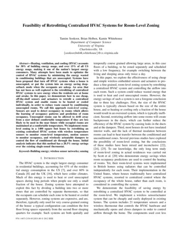
A large sample field study will help determine how these systems work in the real world, andwill assess the actual installed efficiency and performance of combi systems. These field testswill use current high efficiency products tested and optimized in the laboratory to determine theactual energy savings of well-designed combi systems. This report provides results from thelaboratory tests; a later report will cover results from the field study.1.2 Relevance to Building America’s GoalsCombi systems have potential to significantly reduce home energy use. An optimized combisystem can provide space and water heating with a 95% efficient heating plant, compared to aminimum efficiency 78% AFUE furnace and a 0.59 1 energy factor (EF) WH. These metricscannot be compared directly; detailed laboratory and field monitoring is necessary to determineactual savings. The large difference between the efficiency numbers shows the potential forsavings. Removing a naturally drafted WH also allows the home to be more airtight withoutcausing combustion safety issues, and can eliminate combustion makeup air. These twomeasures can further improve the energy performance of a home.Combi systems are feasible in most climate regions. In colder climates the application may notbe possible in larger homes with poorly insulated and leaky envelopes. Currently availableequipment should target homes with space heating loads smaller than 60,000 Btu/h.The implementation phase of this project will install 300 combi systems in Minnesota homes. Atcompletion, the contractors should be ready to install the systems across the state. This projectwill also develop installation guidelines and specifications to increase the success of installationdecisions in all climates.1.3 Cost EffectivenessThe installed cost of a high efficiency combi system may be lower than that of a similarefficiency separate furnace and WH. In a retrofit application, a homeowner can expect to payapproximately 4,000 for a high efficiency (90%–95% AFUE) furnace and 4,000 for a highefficiency (0.80–0.95 EF) WH. 2 In the Minneapolis area, contractors with limited experiencewith combi systems currently bid a high efficiency system for 6,000– 9,000. A large number ofinstallations are expected to reduce costs, much as the cost of high efficiency water heatersdecreased as installations increased over the past few years.A preliminary EnergyPlus analysis of a high efficiency boiler used for space and DHW heatingestimated that natural gas use would be reduced by 12% and source energy by 7% compared toan 80% AFUE furnace and 0.55 EF WH. However, EnergyPlus is not easily adapted and maynot properly model high efficiency combi system performance. EnergyPlus currently does nothave models for performance of heating plants or combi systems. For example, it does notprovide information on variations of efficie
The research will use combi systems with water heater (WH) or boiler heating plants teamed with forced air distribution space heating systems. In each house, the existing furnace will be replaced with a hydronic air handler (AH) that includes an AH, a water coil, and a water pump to circulate water between the heating plant and the coil.