Transcription
Feasibility of Retrofitting Centralized HVAC Systems for Room-Level ZoningTamim Sookoor, Brian Holben, Kamin WhitehouseDepartment of Computer ScienceUniversity of VirginiaCharlottesville, ct—Heating, ventilation, and cooling (HVAC) accountsfor 38% of building energy usage, and over 15% of all USenergy usage, making it one of the nation’s largest energyconsumers. Many attempts have been made to optimize thecontrol of HVAC systems by minimizing the energy wastedin conditioning buildings that are unoccupied. Systems havebeen proposed that turn off HVAC systems when a house isunoccupied, or put the system into an energy saving deepsetback mode when the occupants are asleep. An area thathas not been as well explored is the retrofitting of centralizedHVAC systems to save energy when the residents are at homeand awake. In this paper, we demonstrate how to use cheap,off-the-shelf sensors and actuators to retrofit a centralizedHVAC system and enable rooms to be heated or cooledindividually, in order to reduce waste caused by conditioningunoccupied rooms. We call this approach room-level zoning.Sensors are used to detect occupancy in rooms which allowsthe learning of occupancy patterns and prediction of roomoccupancy. Unoccupied rooms can be allowed to drift awayfrom a user defined comfortable temperature if they are lesslikely to be used in the near future while occupied rooms aremaintained at a comfortable temperature. We implement roomlevel zoning in a 1400 square foot house by retrofitting anexisting centralized HVAC system with wireless temperaturesensors to monitor room-level temperature, motion sensorsto monitor occupancy, and wirelessly actuatable dampers tocontrol the flow of conditioned air through the house. Initialanalysis indicates that this method has a 20.5% energy savingsover the existing single-zoned thermostat.Keywords-Building energy; wireless sensor networks; sensingI. I NTRODUCTIONThe HVAC system is the single largest energy consumerin residential buildings, accounting for 43% of the residential energy consumption in the US [7], and over 60% inCanada [8] and the UK [16], which have colder climates.Much of this energy is used to heat or cool unoccupiedspaces during long periods when people use only a smallfraction of the house. Zoning systems have attempted toexploit this fact by dividing a building into two or morezones that are controlled by separate thermostats, so thatthe occupants can schedule each zone to be heated or cooledseparately. However, zoning systems are expensive, and are,therefore, typically only used for very course-grained zoningof the house: a typical configuration can condition the firstfloor living spaces separately from the second floor sleepingquarters for example. Such systems are both spatially and978-1-4673-2154-9/12/ 31.00 2012 IEEEtemporally course grained allowing large areas, in this casefloors of a building, to be zoned separately and scheduledwith a low frequency, for example switching between theliving and sleeping areas only twice a day.In this paper, we explore the effectiveness of using cheapand simple wireless embedded sensors and actuators to produce a fine-grained, room-level zoning system by retrofittinga centralized HVAC system and controlling the airflow intoeach room. Such a system could reduce wasted energy thatis used to heat and cool unoccupied rooms. However, theenergy savings of such a system is not a foregone conclusiondue to three key challenges. First, the size of the HVACsystem is typically chosen based on the size of the entirehouse, and so heating or cooling only a fraction of the housewould result in an oversized system, which is typically inefficient. Second, restricting airflow into some rooms will createbackpressure in the ducts, which can further reduce theefficiency of the HVAC system by causing leaks in the ductsand at the dampers. Third, most houses do not have insulatedinterior walls, and the lack of thermal insulation betweenrooms can lead to heat transfer between the conditioned andunconditioned zones. Several previous studies have exploredthe possibility of room-level zoning, but the conclusionsof these studies have been mixed and inconclusive [22],[24], [25]. To our knowledge, the only long term studyof room-level zoning in actual residences was carried outby Scott et al. [20] who demonstrate energy savings whenroom occupancy predictions are used to control the heatingof rooms. Yet, their room-level systems were implementedin British homes using radiators that can be controlledindependently for each room. Their implementation in theUnited States, where houses traditionally have centralizedHVAC systems, resorted to centralized control where theoccupancy of the whole house, rather than each room, isconsidered in controlling the system.We demonstrate the feasibility of saving energy byretrofitting a centralized HVAC system to be controlled atthe room-level. We implement a wireless sensor/actuatorsystem that can be cheaply and easily deployed in existinghomes. The system includes 21 temperature sensors and awireless thermostat that controls the HVAC hardware andmechanically opens and closes dampers in order to controlairflow through the home. The components used cost less
than 500, and a production version is expected to costconsiderably less. In contrast, traditional zoning systemsoften cost more that 5000. We deployed our system in a7-room, single-story, 1400 square foot house and measuredthe energy consumption of heating and cooling. Our resultsindicate that the system consumed 20.5% less energy than ifthe HVAC system were controlled by the existing thermostatover a 20-day experimental period. These results indicatethat retrofitting an existing centralized HVAC system forroom-level zoning has a potential for substantial energy savings, and warrants further investigation into this approach.II. BACKGROUND AND R ELATED W ORKTraditional HVAC zoning systems for homes typicallyseparate a house into floors, each of which can be controlledindividually. These systems are often installed more forcomfort than for energy savings, because a single un-zonedsystem that operates on multiple floors will often result in awarm top floor and/or a cold bottom floor. Floor-level zoningalso makes sense in many homes that have bedrooms on thetop floor and living areas on the bottom floor. Floor-levelsystems have resulted in homeowners saving as much as 2030% as compared to single zoned systems [25]. However,these systems are expensive and the energy savings cantake years or even decades to produce a positive return oninvestment. Furthermore, it can be difficult to retrofit anexisting home with a zoning system.Commercial buildings often use zoning systems that divide a single floor into multiple rooms. This is especiallycommon in hotels, banquet halls, and office buildings.For example, the discharge-air-regulation technique (DART)uses temperature sensors to control the HVAC fan speed [9].Other systems include the Millennial Net [15] and SiemensAPOGEE [10]. Just like the residential zoning systems,these solutions are expensive and are much easier to addto a new installation. Similarly, micro-environment systems(also called task-ambient conditioning) allow a worker in anoffice building to have fine-grained control over the ambientconditions around his or her working space, typically adesk. Several systems, including Personal Environmentsfrom Johnson Controls [4] and Habistat from Interface Architectural Resources, are currently commercially available.The individually controlled spaces are not insulated fromeach other and operate within a single thermal zone. Thesesystems are designed for occupant comfort over energyefficiency. The systems can produce some energy savingsby not conditioning desks that are not occupied, and severalstudies have shown substantial savings of micro-environmentsystems [2], [18], [19]. However, the cost of these systems isbetween 20,000 and 100,000 per desk, which is too largeto produce a positive return on investment. Furthermore, thisapproach is designed for offices and would be difficult totransfer to homes, where usable space can be more difficultto instrument than a desk or cubicle.Numerous studies have explored the effect of providingindividual temperature control in rooms, but the results havebeen mixed and inconclusive. One experiment tested theenergy used to heat a single-room with 10 registers andleaky ducts while closing an increasing number of ventregisters [22]. The results indicate that closing registersincreases the pressure within ducts causing greater ductleakage and reduced system efficiency. However, since allregisters were within the same room, this study did notdetermine whether the reduced efficiency outweights thesavings produced by conditioning a smaller area; all registerconfigurations were conditioning the same sized area.A subsequent study developed an automated vent louverdesign for room-level zoning [24], similar to the one developed for our system and other similar systems [17]. Theauthors evaluate the system by dividing a house in Danville,CA into four zones and increase the temperature in eachzone by 2-5 F. They also increased the temperature in theentire house by the same amount. The results indicate thatit takes less energy to increase the zone temperature perdegree than it takes to increase the whole house temperatureper degree, since the smaller zones heat up faster thanthe whole house, allowing the system to turn off sooner.However, this study only measured the transitional timeand energy of a room-level zoning system, and it did notmeasure the steady state energy. In other words, it doesnot show the difference in energy required to maintain aparticular temperature in a zone versus the whole house. Thisdistinction is profound, because thermal leakage betweenadjacent rooms could cause system to also turn back on morequickly, nullifying the energy savings of turning off morequickly. This is often called short cycling, and is knownto decrease system efficiency as well as reduce the overalllifetime of the equipment.The latest attempt at occupancy-based room-level heatingcontrol is a system called PreHeat [20]. The authors implement occupancy-based heating control in houses in theUnited States and United Kingdom. In the United Kingdom,the authors exploited the radiators that are used to heatrooms in order to implement a room-level controlled heatingsystem. In the United States, since the houses used a centralized HVAC system for heating, the authors used occupancybased whole-house control similar to that proposed by Luet al. [14]. The main weakness of PreHeat that we attemptto address is the lack of interaction between rooms in anyof the models used for prediction. For instance, the authorspredict the occupancy of each room based on the history ofoccupancy of that particular room without considering theoccupancy of any other rooms. We demonstrate that takinginto consideration occupancy patterns across a house wouldlead to higher accuracies in predicting the occupancy of aparticular room. The authors also use a very simple thermalmodel to predict when a room should be preheated. Themodel is simply the average amount of time it took to in-
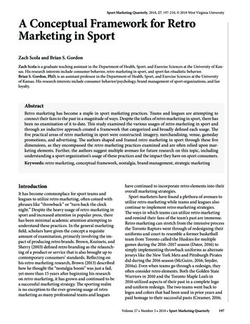
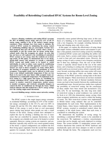
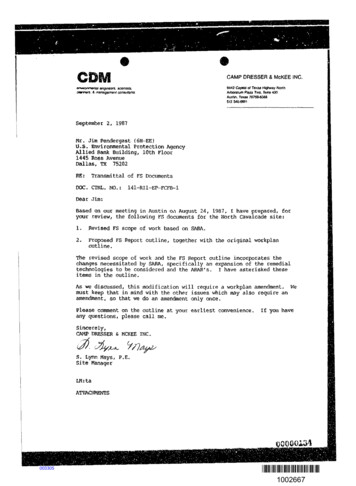
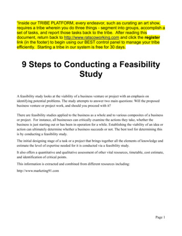
3530Energy (kWh)25201510500102030402Floor area (m )506070Figure 1. With an ideal system, the amount of energy used for conditioninga building is almost proportional to the floorspace being conditioned.crease the room temperature by a degree based on historicaldata. We present a model, which we are currently workingon, that takes into consideration the thermal interactionsbetween rooms.Finally, there have been patents filed for occupancybased zoning of HVAC systems using security systems [3]or motion sensors [21] to detect occupancy. While thesesystems attempt to solve the problem we are addressing, theeffectiveness of their approach is not evaluated. Also, thesesystems fail to address hardware safety concerns that arisewith implementing room-level zoning using a centralizedHVAC system. Our approach is cognizant of the shortcycling and back-pressure that could reduce the lifespanof HVAC hardware and attempts to minimize the potentialdamage to hardware.III. I NTUITION AND P RELIMINARY S TUDIESBefore implementing our room-level zoning system, weperformed two simulation studies to better understandwhether such a system should be expected to reduce energysavings, and why. These two studies are explained in thefollowing subsections.A. Effect of an Oversized HVAC SystemIn houses with a typical non-zoned central heating andair conditioning system, the size of the system is chosenbased on the expected load of the entire house. Therefore,using the same system to heat or cool only a fraction ofthe house would mean that the system is oversized for theconditioned space. It is well known that oversizing an HVACsystem results in reduced efficiency of the system. Our firststudy was designed to determine how much this oversizingwould reduce the potential for energy savings of a roomlevel zoning system.We used the EnergyPlus building energy simulationframework [5] to heat multiple buildings in simulation, withincreasing size from 5m2 to 65m2 . The model buildings hadidealized insulation and leakage properties. All buildingswere heated with the same sized HVAC system, whichwas sized for a 65m2 building. The results are shown inFigure 1, which indicate that the amount of energy requiredto heat a smaller building does indeed decrease, even ifthe size of the HVAC system remains the same. The sublinear curve indicates that some efficiency is lost for smallerbuildings due to the oversizing of the system. However,this loss in efficiency does not outweigh the gains fromheating a smaller space. From these results, we postulatethat room-level zoning can be effective, even when appliedby retrofitting a home with an existing HVAC system thatwas sized for the entire house.B. Inter-room LeakageHomes often have thin non-insulated walls and even doorsbetween adjacents rooms, which can reduce the effectivenessof room-level zoning because of thermal leakage betweenrooms. Our second study was designed to explore how muchthis leakage would reduce the energy savings of a roomlevel zoning system. We used the EnergyPlus simulationframework to heat a single room in a two-room building.We used five variations of the floor plan of the house, andthe conditioned room had a different number of exteriorwalls in each variation. The five variations are shown alongthe x-axis of Figure 2, and the energy required to heatthe shaded room for each floor plan is shown as a bargraph above each variation. These results indicate that theenergy required to condition a room is dramatically reducedas the number of exterior walls of the room decreases.In other words, a neighboring room is a better thermalinsulator than an exterior wall, even if the wall between theconditioned room and the neighboring room is not insulated.This result indicates that leakage between conditioned andunconditioned zones will not eliminate the energy-savingpotential of room-level zoning.C. Room OccupancyFinally, our preliminary analysis showed that, even whena home is occupied, the occupants use only a fraction ofthe house. For example, empirical analysis of one home isshown in Figure 3, showing that primarily only one room isused at night, three rooms are used in the evening, and fourrooms are used in the morning.IV. C HALLENGESImplementing a room-level zoned centralized HVAC system poses many practical challenges. These include, maintaining a minimum airflow and preventing short cycling forHVAC hardware safety, predicting room occupancy withno history, and coordinating the conditioning of zones. Wedescribe these issues below.
which air flows over the coils that carry the refrigerant. Thelower airflow would result in insufficient heat transferredto the refrigerant causing it to return to the compressor inliquid form, without fully evaporating, which can damagethe compressor.Zoning a centralized HVAC system involves closing ductsso that air only flows to a subset of a house. If too manyducts are closed, or ducts are closed in a wrong configuration, back-pressure could build up resulting in energywastage due to leakage and equipment damage. In order toenable room-level zoning of a centralized HVAC system thebuildup of back-pressure has to be taken into considerationwhen making actuation decisions.B. Short CyclingFigure 2.The energy required to condition a room decreases as itsnumber of exterior walls is decreased. The x-axis depicts the positionof the conditioned room (shaded) with respect to the unconditioned room(unshaded).BedroomC. Occupancy PredictionKitchenBathroomToilet12AMManufacturers recommend a minimum time for which anHVAC system should operate at a particular stage beforetransitioning to a lower stage, for instance transitioning fromstage 2 to stage 1 or turning off from stage 1. Transitioning before this minimum threshold increases the wear andtear on the equipment due to it cycling more frequentlyand doesn’t allow the pressure to equalize between cycles.Therefore, in implementing a system that controls the HVACequipment at a fine granularity, it is essential that we ensurethe compressor is not short cycled. This adds another factorto be considered when making actuation decisions.3AM6AM9AM12PM3PM6PM9PM12AMFigure 3.The frequency of room usage throughout a day changes.Darker colors indicate lower frequency while brighter colors indicate higherfrequency usage with yellow being the highest frequency.A. Minimum AirflowHVAC systems are rated for a certain output airflowdepending on the operating stage. For instance, the HVACsystem in the house where our experiments were carriedout produces 830 f t3 /min (CFM) of conditioned air whencooling in stage 1, 1200 CFM of air when cooling instage 2, etc. The ductwork for HVAC systems are carefullydesigned so as to allow most of this air to leave throughregisters. This prevents pressure buildup in ducts, backpressure, which can increase leakage through cracks inducts and improperly insulated connections. Back-pressurecan also damage HVAC equipment by reducing the rate atOccupancy-based HVAC systems can be classified aseither reactive or predictive. Reactive systems use roomlevel controllable HVAC equipment such as radiators orwindow air-conditioner units that can be turned on andoff independently. These systems then monitor rooms foroccupancy and turn on or off the occupied room’s conditioning unit in response to detected occupancy. Coordinationbetween zones is not an issue for such systems since theheating or cooling units are independent. Reactive systemswith centralized HVAC systems have been implemented, butthey either focus on whole house conditioning so that thesystem turns on when the house is occupied and off whenthe house is unoccupied, or rely on customized ducts withbypass ducts that prevent back-pressure. While bypass ductscan prevent the problems associated with back-pressure, apurely reactive centralized zoned system fails to exploita lot of the energy savings possible due to being zonedbecause it has to turn on whenever a room that is not at thesetpoint is occupied. In a house with a lot of activity, sucha control scheme could result in a zoned system being nomore efficient than a centralized HVAC system because itis always on. Another drawback to reactive systems, bothwhole-house and room-level, is the need to quickly heator cool a space when occupancy is detected. This rapidconditioning can be less efficient than maintaining the spaceat a setpoint.
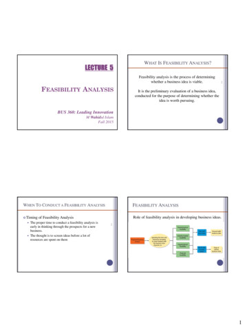
Predictive systems attempt to predict when a house orrooms are going to be occupied and start pre-heating orcooling the space so that it can be conditioned over a longerperiod of time using a more efficient HVAC stage than therapid conditioning required during reaction. Yet, predictionis difficult due to the large amount of historical data that hasto be collected in order to make an accurate prediction. Thisdifficulty increases with the temporal granularity with whicha prediction has to be made. For instance, it is much easierto predict which rooms would be used within the next sixhours based on history, but much harder to accurately predictwhich rooms would be used within the next five or tenminutes. The accuracy of prediction increases as historicaldata is collected, but the amount of data necessary increasesas the size of the prediction window decreases.D. Zone CoordinationThe biggest challenge to implementing room-level zoning using a centralized HVAC system is coordinating theconditioning of zones so that energy is not wasted by thecompressor constantly being in operation or air leakingbetween conditioned and unconditioned zones. We attemptto minimize the inefficiency by conditioning thermally homogeneous zones together so that the temperature gradientwithin such zones is relatively small. This would reduce theamount of leakage out of conditioned rooms and minimizethe amount of time the HVAC system has to be turned onwhen an unoccupied room is occupied because it wouldbe close, in temperature, to the neighboring rooms and,thus can quickly be brought to the setpoint after which thecompressor can be turned off.V. I MPLEMENTATIONWe implemented a room-level zoning system in order toempirically test the ability to save energy with this approach.Our implementation involves: (1) sensing temperature atthe room-level, (2) controlling air-flow into rooms, and (3)controlling the HVAC system.A. Sensing House TemperatureWe monitor the home’s temperature at a fine granularity by instrumenting the house with wireless temperature sensors placed at various points on the walls. Forthe deployment discussed in this paper, we used 21 offthe-shelf temperature sensors manufactured by La CrosseTechnology [13]. Because the temperature across the houseis not uniform, one challenge in designing a room-levelzoning system is to choose how to process the temperaturereadings to approximate the true average air temperature ineach room. This problem can also be addressed for wholehouse conditioning when more than a single temperaturesensor is available [12].Figure 4 shows the temporal variations of several temperature sensors placed throughout the house. One sensor isFigure 4. The variation of temperature on a sensor placed on an internalwall, an external wall, and near the return duct.placed in the center of the house, directly in front of the onlyreturn register, and therefore is exposed to a mix of air fromall rooms. Another sensor is placed on an internal wall of thehouse, and a third sensor is placed on an external wall. Thefigure shows that the temperature sensor on the internal wallvaries with the temperature of the individual room, whichis slightly more than the variation of the centrally placedsensor. However, the sensor on the external wall is subjectto wild temperature swings. On the left side of the graph, it isclear that the sensor has much greater downward swings thanthe internal sensors. This is because is it subject to direct airflow from the ducts, which are typically placed on externalwalls. It is also subject to heat that concentrates aroundthe window mid-day. Because of these large temperaturefluctuations, we decided to use only sensors on the internalwalls of each room: the temperature in a zone was calculatedas the average of the temperatures of each of the internalsensors in the rooms comprising the zone.B. Controlling Air-flow into RoomsIn order to control the airflow into individual rooms, wedesigned and built active registers and dampers that can bewirelessly opened or closed. While controllable registers arecommercially available, they actuate based on either presettemperatures or temporal schedules. Commercial active registers that are controllable through a remote control would behard to integrate with our wireless control system and suchregisters are expensive, costing over 50 each. By designingour own registers by retrofitting passive registers with servomotors, we were able to build active registers for under 20each, excluding the cost of the radio and microcontroller,that integrated wirelessly with the rest of our infrastructure.Our design improved through three generations as shown inFigure 5. We implement the registers using cheap, off-theshelf (COTS) components including an operable register, aservo motor, and a small amount of custom circuitry. Thesecomponents resulted in a cost of less than 20 per registerexcluding the cost of the TelosB mote, which was used forwireless communication. We built upon several prototypes
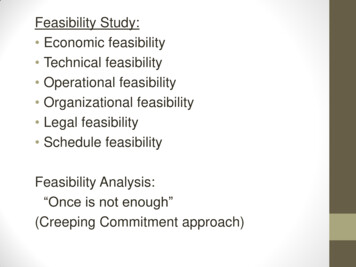
C. Controlling the HVAC System1100Maximum AirflowAverage AirflowOur system uses a simple state machine (Figure 7) tocontrol the HVAC system through four possible stages:Float, Hold, Cool 1, and Cool 2. Cool 1 and Cool 2are intended to represent different stages of the HVACsystem in which the compressor and hair handler operate atdifferent cooling capacities. Hold causes the HVAC systemto maintain the current temperature at the thermostat, andFloat causes the HVAC system to turn off.1000Air Handler Flow (cfm)9008007006005004001234567Number of closed registers8910Figure 6. As more registers are closed, some efficiency is lost and thetotal total air volume output by the system ermSPThermSPAction ThermTemp 1 ThermTemp ThermTemp - 1 ThermTemp - 2Table IT HE OPERATING STAGE OF THE HVAC EQUIPMENT WAS CONTROLLEDBY ADJUSTING THE THERMOSTATIC SETPOINT ThermSP WITH RESPECTTO THE TEMPERATURE THAT WAS SENSED BY THE THERMOSTATThermTemp.and even commercial versions of similar hardware that arecurrently available [22], [23], [24],but go beyond thesedevices by integrating them into a cooperative, wirelesssystem.We measured the effectiveness of the registers using thebench-top testing framework shown in Figure 5(d). Thefirst generation registers were not very efficient at blockingair when closed. The second generation registers improvedthis aspect by blocking nearly 100% of airflow but wasnoisy when opening and closing. Due to these reasonswe resorted to dampers used in commercially implementedzoned systems as our third generation of airflow controllers.We measured how effective these registers are at directingairflow into different rooms using a Kestrel 4100 Pocket AirFlow Tracker manufactured by Nielsen-Kellerman [11]. Thissensor is placed above the register and provides a measureof airflow in terms of cubic feet per minute (CFM) thatis coming out of the register. This measurement is basedon the known size of the register and the speed of theair. Figure 6 shows that the total airflow coming from allregisters is reduced as an increasing number of registers areclosed. When all registers are open, the average airflow isapproximately 800 CFM, which matches the specification ofthe air handler in this house. However, as more registers areclosed, the average airflow approaches 450 CFM, which isalmost half. Total airflow does not approach zero becausesome air escapes even from the closed registers. This resultverifies that closing registers does decrease the overallefficiency of the system because it reduces the total airflowoutput, as suggested by [22]. Therefore, actively coolingonly half the house would not cause double the amount of airto be available to the cooled zone, because some air is lostdue to backpressure, increased duct friction, duct leakage,and leakage from the closed registers.In order to control the HVAC equipment, our systemmust interface through an Internet-controllable thermostatmanufactured by BAYweb [1]. However, the BAYweb thermostat only allows its setpoint to be changed; it does notallow direct control over the equipment. In order to controlthe equipment, therefore, we modify the setpoint of thethermostat T hermSP to be higher, lower, or equal tothe temperature measured at the thermostat T hermT emp.When we want to put the equipment into the float state, weuse a setpoint that is higher than the current temperature.This causes the thermostat to turn off the equipment. Similarly, when we want to hold or lower the temperature, weuse a setpoint that is the same as or lower than the currenttemperature, respectively. To lower the temperature quickly,i.e. to use stage Cool 2, we use a setpoint that is two degreeslower than the setpoint. This exploits the PI controller that isbuilt into the thermostat, which causes the equipment to gointo high stage cooling when the temperature is two degreesfrom the setpoint for more than 5 minutes. The operation ofthe system is summarized in Table I. This coarse-grainedcontrol over the equipment is not ideal and could havecaused some loss of efficiency and energy waste. In futurework, we expect an improved control system to producebetter results.VI. E VALUATIONWe deployed our room-level zoning system in an 8room, single story, 1200 square foot residential buildingshown in Figure 8. For simplicity, we divided the houseinto two zones. The red zone composed of the living room,dining room, and kitchen is actively conditioned between8:00 AM and 9:30 PM while the blue zone composed ofthe bedroom, nursery, toilet, and mudroom is conditionedbetween midnight and 8:00 AM. Between 9:30 PM and
(a) 1st Generation(b) 2nd Generation(c) 3rd Generation(d) Bench-Top Test RigFigure 5. Three generations of active registers. (a) The first generation uses servo motors and a rotating louver design, but exhibited too much leakage.(b) The second generation uses a sliding gate design to solve the leakage problems, but causes too much noise. (c) The third generation is a commercialin-line damper with a servo motor used for traditional zoning applications. (d) The bench-top test rig used to verify that the second generation wirelesslycontrolled active registers have almost no air leakage.F
HVAC systems, resorted to centralized control where the occupancy of the whole house, rather than each room, is considered in controlling the system. We demonstrate the feasibility of saving energy by retrofitting a centralized HVAC system to be controlled at the room-level. We implement a wireless sensor/actuator


![[IV‐ADV‐9‐A] Tips and Tricks for Payroll and Human Resources](/img/9/tips-and-tricks-payroll-and-hr.jpg)