Transcription
IJRET: International Journal of Research in Engineering and TechnologyeISSN: 2319-1163 pISSN: 2321-7308ANALYSIS OF AERODYNAMIC CHARACTERISTICS OF ASUPERCRITICAL AIRFOIL FOR LOW SPEED AIRCRAFTP.Sethunathan1, M.Niventhran2, V.Siva2, R.Sadhan Kumar21Asst.Professor, Department of Aeronautical Engineering, Paavaai Group of Institutions, Namakkal2UG Students, Department of Aeronautical Engineering, Paavaai Group of Institutions, NamakkalAbstractThe main goal of the proposed paper is the analysis of aerodynamic characteristics of an various supercritical airfoils like 0406,0412, 0706 and 1006 influence on the dramatic improvement in lift and reduction of drag in low speed aircraft. In a precedentwork, a cusp like structure at the trailing edge of an unsymmetrical airfoil produces a very high improvement in climbingperformance of an aircraft.The computational analysis of aerodynamic characteristics of supercritical airfoil design and analysis by using ICEM- CFD. Inthis work certain supercritical airfoils set on an ICEM- CFD without changing benchmark setup, in order to compare theircoefficient of lift ( CL ) and coefficient of drag ( CD ) at various angle of attack (α). The pressure distribution was measured toverify global and local effects of airfoil structure. The test conducted in subsonic speed at flow velocity of 25m/s. The result showsthat certain supercritical airfoil (0406) configuration reduced the drag and improve coefficient of lift (C L) by 15-20% comparedwith the baseline model.Keywords: Supercritical airfoil, Lift Curve Slope, Coefficient of Lift, ICEM–CFD, Drag ----------------------------------------------1. INTRODUCTION2. LITERATURE REVIEW1.1 Flow Past a Supercritical AirfoilA concerted effort within the National Aeronautics and SpaceAdministration (NASA) during the 1960's and 1970's wasdirected toward developing practical airfoils with twodimensional transonic turbulent flow and improved dragdivergence Mach numbers while retaining acceptable lowspeed maximum lift and stall characteristics and focused on aconcept referred to as the supercritical airfoil. This distinctiveairfoil shape, based on the concept of local supersonic flowwith isentropic recompression, was characterized by a largeleading-edge radius, reduced curvature over the middleregion of the upper surface, and substantial aft camber.The flow over a finite wing is different from that of flow overan airfoil. Transonic Jet aircrafts fly at speed of 0.8-0.9 Machnumber. At these speeds speed of air reaches speed of soundsomewhere over the wing and compressibility effects start toshow up. The free stream Mach number at which local sonicvelocities develop is called critical Mach number. It isalways better to increase the critical Mach number so thatformation of shockwaves can be delayed. This can be doneeither by sweeping the wings but high sweep is notrecommended in passenger aircrafts as there is loss in lift insubsonic speed and difficulties during constructions. Soengineers thought of developing an airfoil which can performthis task without loss in lift and increase in drag. Theyincreased the thickness of the leading edge and made theupper surface flat so that there is no formation of strongshockwave and curved trailing edge lower surface whichincreases the pressure at lower surface and accounts for lift.1.2 Scope and Objective of the Present WorkIn the present work, first of all we have analyzed the effect ofnumber of airfoils to reduce the drag. We computed flowover the wing with different configurations of supercriticalairfoils. The four configurations of models are airfoil (0406,0412, 0706, and 1006) results have been compared to theexperimentally reported results from the literatures 0406 isgood performance for CL, CD, and Cp analyzed by ICEMCFD.2.1 Effects of Trailing-Edge ThicknessThe design philosophy of the supercritical airfoil requiredthat the trailing-edge slopes of the upper and lower surfacesbe equal. This requirement served to retard flow separationby reducing the pressure recovery gradient on the uppersurface so that the pressure coefficients recovered to onlyslightly positive values at the trailing edge. For an airfoilwith a sharp trailing edge, as was the case for earlysupercritical airfoils, such restrictions resulted in the airfoilbeing structurally thin over the aft region. Because ofstructural problems associated with sharp trailing edges andthe potential aerodynamic advantages of thickened trailingedges for transonic airfoils, an exploratory investigation wasmade during the early development phases of thesupercritical airfoil to determine the effects on theaerodynamic characteristics of thickening the trailing edgeshows that increasing the trailing-edge thickness of aninterim ill-percent-thick supercritical airfoil from 0 to 1.0Volume: 03 Issue: 06 Jun-2014, Available @ http://www.ijret.org179
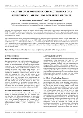
IJRET: International Journal of Research in Engineering and Technologypercent of the chord resulted in a significant decrease in wavedrag at transonic Mach numbers; however, this decrease wasachieved at the expense of higher drag at subcritical Machnumbers.3. COMPUTATIONAL MODELLING OF FLUIDFLOWCFD is one of the branches of fluid mechanics that usesnumerical methods and algorithms to solve and analyzeproblems that involve fluid flows. Computers are used toperform the millions of calculations required to simulate theinteraction of fluids and gases with the complex surfacesused in engineering. More accurate codes that can accuratelyand quickly simulate even complex scenarios such assupersonic or turbulent flows4.SUPERCRITICALeISSN: 2319-1163 pISSN: 2321-7308direction, z-axis is in the span wise direction. The solution isstarted and allowed to converging and attains periodic nature.Conditions for the Inviscid Model INLET CONDITION- INLETOUTLET CONDITON- OUTLETAIRFOIL SURFACE- WALLTOP AND BOTTOM SURFACE - WALLSOLVER- CFXMODEL- INVISCIDTIME- STEADY FLOWDENSITY- 1.225 Kg/m35.2 Inviscid Flow over a Supercritical Airfoil (0406)MeshingAIRFOILNOMENCLATURE Wing configurationWing configurationWing configurationWing configurationWing lengthViscosityDensity- SC (2) - 0406- SC (2) – 0412- SC (2) – 0706- SC (2) - 1006- 0.25 m- 1.8310E-05- 1.125 kg/m35. NUMERICAL RESULTS AND GRAPHSIn order to ensure that the numerical simulation of steadyflow over airfoil at different orientations using ICEM-CFD isproperly carried out; a few benchmark test cases forvalidation were simulated first.5.1 Inviscid Flow over a Supercritical AirfoilFor the numerical simulation of flow over wing usingcommercial package ICEM-CFD has been used to solve thebasic governing equations for velocities and other quantities.Fig. 2 Meshing of supercritical airfoil 0406The flow over a wing for Reynolds number 2,50,000 iscomputed using ICEM-CFD simulating in supercriticalairfoil. The variation of lift coefficient Vs angle of attackshown.Fig,7 As well as the variation of drag coefficient hasshown Vs angle of attack shown in Fig.8 and CL Vs CD inFig. 9 .5.3 Comparison of Inviscid Flow SupercriticalAirfoil (0406, 0412, 0706, 1006) MeshingFig.1. Domain wallFig. 3 Meshing Of Supercritical Airfoil 0406The schematic representation of the computational domainStructured grid in Cartesian coordinates is chosen, where xaxis is along the free stream direction, y-axis is in the verticalVolume: 03 Issue: 06 Jun-2014, Available @ http://www.ijret.org180
IJRET: International Journal of Research in Engineering and TechnologyeISSN: 2319-1163 pISSN: 2321-73085.4 Analyzing Flow VelocityTable 1 SC (2) - 312AOA(α)-5-3-101357911131516Fig. 4.Velocity distribution over a Supercritical Airfoil 04065.5 PressureFig. 5.Pressure distribution over a supercritical airfoil 04065.6 Streamline VelocityFig. 6 Stream line velocity of supercritical airfoil 0406AOA(α)-5-3-101357911131516Table 2 SC (2) - able 3 SC (2) - 1.1041.1581.1721.161AOA(α)-5-3-1013Table 4 SC (2) – 50.00750.0090.00930.00990.0117Volume: 03 Issue: 06 Jun-2014, Available @ http://www.ijret.org181
IJRET: International Journal of Research in Engineering and 02540.04320.0680.1006eISSN: 2319-1163 pISSN: 0.67060.44060.24120-51006-0.2 0-0.45101520α-0.6-0.8Fig. 7 Coefficient of lift (CL) VS Angle of Attack 41270610060510α1520Fig. 8 Coefficient of drag (CD) VS Angle of Attack (α)1.5CD-0.514060.54120706-0.5 0-1CL0.511006Fig 9 Coefficient of lift (CL) Vs Coefficient of lift (CD)Volume: 03 Issue: 06 Jun-2014, Available @ http://www.ijret.org182
IJRET: International Journal of Research in Engineering and TechnologyeISSN: 2319-1163 pISSN: 2321-7308Fig.10. CP VS LOCATION6. CONCLUSIONSComputational investigations have been performed toexamine the effectiveness of the various supercritical airfoilmounted at varying angle to improve the performance of awing in subsonic flow. Combining the Computationalanalysis measurement results with the experimental result,the following are presented for analysis performance due tovarious supercritical airfoils.[6]This distinctive airfoil shape, based on local supersonic flowwith isentropic recompression, was characterized by a largeleading-edge radius, reduced curvature over the middleregion of the upper surface, and substantial aft camber. Thisreport has summarized the NASA supercritical airfoildevelopment program in a chronological fashion, discussedsome of the airfoil design guidelines, and presentedcoordinates of a matrix of family-related supercriticalairfoils with thicknesses of 2 to 18 percent and design liftcoefficients from 0 to 1.0.[8][7][9][10]Low- Speed Airfoil Section. NASA TM-78650,1978.McGhee, Robert J.; and Beasley, William D." LowSpeed Aerodynamic Characteristics of a 13-PercentThick Medium-Speed Airfoil Designed for GeneralAviation Applications. NASA TP-1498, 1979.McGhee, Robert J.; and Beasley, William D.: LowSpeed Aerodynamic Characteristics of a 17-PercentThick Medium-Speed Airfoil Designed for GeneralAviation Applications. NASA TP-1786, 1980.McGhee, Robert J.; and Beasley, William D.: WindTunnel Results for a Modified 17-Percent-ThickLow- Speed Airfoil Section. NASA TP-1919, 1981.Ferris, James D.; McGhee, Robert J.; and Barnwell,Richard W.: Low-Speed Wind-Tunnel Results forSymmetrical NASA LS (1)-0013 Airfoil. NASA TM4003, 1987.14. Whitcomb, Richard T.; and Clark, Larry R.: AnAirfoil Shape for Efficient Flight at SupercriticalMach Numbers. NASA TM X-1109, 1965.From supercritical airfoil 0406 is we can conclude thatproduces more lift and lesser drag compare to the othersupercritical airfoil.REFERENCES[1][2][3][4][5]McGhee, Robert J.; and Beasley, William D.: LowSpeed Aerodynamic Characteristics of a 17-PercentThick Airfoil Section Designed for General AviationApplications. NASA TN D-7428, 1973.Whitcomb, Richard T.: Review of NASASupercritical Airfoils. ICAS Paper No. 74-10, Aug.1974McGhee, Robert J.; and Beasley, William D.: Effectsof Thickness on the Aerodynamic Characteristics ofan Initial Low-Speed Family of Airfoils for GeneralAviation Applications. NASA TM X-72843,1976McGhee, Robert J.; and Beasley, William D.: LowSpeed Wind-Tunnel Results for a Modified 13Percent- Thick Airfoil. NASA TM X-74018, 1977McGhee, Robert J.; and Beasley, William D.: WindTunnel Results for an Improved 21-Percent-ThickVolume: 03 Issue: 06 Jun-2014, Available @ http://www.ijret.org183
The computational analysis of aerodynamic characteristics of supercritical airfoil design and analysis by using ICEM- CFD. In this work certain supercritical airfoils set on an ICEM- CFD without changing benchmark setup, in order to compare their coefficient of lift ( C L ) and coefficient of drag ( C D ) at various angle of attack (α). The .