Transcription
JurnalTeknologiFull paperAerodynamic Behavior of a Compound Wing Configuration in GroundEffectSaeed Jameia, Adi Maimuna*, Shuhaimi Mansorb, Agoes Priyantoa, Nor Azwadic, M. Mobassher TofaaaDepartment of Marine Technology, Faculty of Mechanical Engineering, Universiti Teknologi Malaysia, 81310 UTM Johor Bahru, Johor, Malaysiaof Earonautical Engineering, Faculty of Mechanical Engineering, Universiti Teknologi Malaysia, 81310 UTM Johor Bahru, Johor, MalaysiacDepartment of Termo. Fluids, Faculty of Mechanical Engineering, Universiti Teknologi Malaysia, 81310 UTM Johor Bahru, Johor, MalaysiabDepartment*Corresponding author: adi@fkm.utm.myArticle historyAbstractReceived :1 August 2013Received in revised form :15 November 2013Accepted :5 December 2013The aerodynamic coefficients of wing in ground effect can be affected with its design which can be themain parameter for efficiency of wing-in-ground effect craft. In this study, the aerodynamic coefficientsof a compound wing were numerically determined in ground effect. The compound wing was divided intothree parts with one rectangular wing in the middle and two reverse taper wings with an anhedral angle atthe sides. An NACA6409 airfoil was employed as a section of wings. Three dimensional (3D)computational fluid dynamics (CFD) was applied as a numerical scheme. A realizable k-ε turbulent modelwas used for simulation the turbulent flow around the wing surfaces. For validation purpose, thenumerical results of a compound wing with aspect ratio 1.25, at ground clearance of 0.15 and differentangles of attack were compared with the current experimental data. Then, the aerodynamic coefficients ofthe compound wings were computed at various ground clearances and angle of attack of 4 . According topressure and velocity distribution of air around wing surfaces, ground clearance had considerable effectson ram effect pressure and tip vortex of the compound wing, and aerodynamic coefficients of thecompound wing had some improvements as compared with the rectangular wing.Graphical abstractKeywords: Aerodynamic coefficients; cfd simulation; compound wing; wind tunnel, wing-in-groundeffect 2014 Penerbit UTM Press. All rights reserved. 1.0 INTRODUCTIONRecently, many countries started to work on WIG crafts anddeveloped because of their advantages such as fuel saving, highspeed compared to other water vehicles transport. The study onconfiguration of WIG crafts experimentally and theoretically isinvestigated to improve their aerodynamic performance. Theprincipal means to develop lifting force is the ram effect; lift isimproved when flow underneath the wing body aroundstagnation point on the pressure surface (lower surface of body)is trapped. The gathering of high pressure on lower surface andlow pressure on upper surface of the body provides a high liftingforce which is increased the source of supporting.Two phenomena influence on aerodynamic characters ofwing when a wing approaches to the ground. These are calledspan dominated and chord dominated ground effect. The mainparameter related to span dominated ground effect is h/b(height-to-span ratio) and for chord dominated ground effect ish/c (height-to-chord ratio). The span dominated ground effectcauses a reduction in drag force. There are two main sourcedrags for aircraft which are called the viscous drag and induceddrag. The viscous drag is created by friction between the air andsurface of the aircraft; hence it depends on wetted area. Theinduced drag is related to generation of lift. Positive lift isgenerated when the static pressure on pressure side (lowersurface) is greater than that on suction side (upper surface) ofwing. The higher pressure on lower surface meets the lowerpressure on upper surface at the tip of wing, subsequentlyaround the wingtip; a current of the air will appear from lowersurface to the upper surface that is called tip vortex. This vortextakes energy from aircraft; therefore it defines as a drag. Theaspect ratio of wing effects on tip vortex, for high aspect ratiowing the difference between pressure on upper and lowersurfaces is lower at wingtip then the tip vortex is weaker andconsequently induced drag is smaller. When the wing is near theground the tip vortex is trapped by the ground and reduces thestrength of vortices, it seems that the effective aspect ratio of thewing is greater than geometric aspect ratio [1].The chord dominated ground effect mostly can increase liftforce. When the wing approaches to the ground, a higherpressure (ram effect) is generated at lower surface of the wingthat is called dynamic air cushion. For very low groundclearance (h/c) the air flow reaches to stagnate accordingly thehighest pressure is appear at lower surface of the wing. At smallground clearance and very small or negative angle of attack,When the lower surface of wing is convex a suction effect is66:2 (2014) 21–27 www.jurnalteknologi.utm.my eISSN 2180–3722
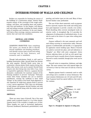
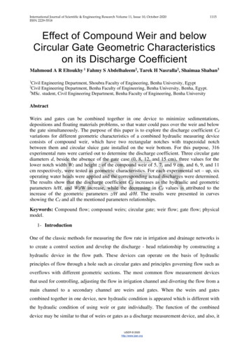
22Adi Maimun et al. / Jurnal Teknologi (Sciences & Engineering) 66:2 (2014), 21–27created at bottom and pulled down the wing. This outcome canuse for design of race car to control it at high speed. Normally,the wing of WIG crafts should have as flat as possible andpositive of angle of attack [1].Several initial experimental and computational techniquesto calculate the lift by special shape of the body in groundproximity can be found in the references [2-4]. Yang et al. [5]worked on longitudinal stability of WIG craft respect to somedesign parameters such as wing section, wing plan form,stabilizer, and endplate. They showed that the s-shaped wingmodifies longitudinal stability at certain angle of attack but losta little lift compared to popular wing section like Clark-y. Also,they depicted a tail wing had more effect on center in pitch thancenter in height, because the tail position was out of groundeffect. It was shown the aerodynamic centers of forward swept(FS) wing and reversed forward swept (RFS) wing is nearer toleading edge of wings contrast to rectangular wing one. Theperformance (L/D) of rectangular wing was lower RFS wingand greater than FS wing in extreme ground effect. The canardwing as a replacement for tail wing is an alternative designparameter for stability of WIG craft [6-7]. Li et al. [7] showedthat the canard wing causes the aerodynamic centers shift toleading edge of main wing without changing the relationshipbetween centers. This is an advantage for locating the center ofgravity. The weak point of canard wing was reported on itsheight stability, although it has good behaviour on pitchingstability. They established the drag force of the canard wing islesser than tail wing that gives higher efficiency. Lee et al. [8]carried out the aerodynamic characteristics of rectangular wingwith anhedral angle and endplates respect to different angles ofattack and ground clearances. Three configurations wereexamined, clean wing, wing with endplate and wing withanhedral angle. The lift to drag ratio of the wing with anhedralangle was in the middle among them, additionally, its heightstatic stability satisfied for all angle of attacks and groundclearances. They described that the variations of lift coefficientof wing with anhedral angle versus Reynolds numbers is thesmallest, while for drag coefficient is the largest compared toother models. The planform of wing is a new challenge indesign of WIG craft [9-10]. Yang and Yang [9] numericallyanalyzed two configurations of WIG craft, one with airplaneconcept and another with Lippisch concept. The main wing ofairplane type was a rectangular wing, and a reverse forwardswept wing was used for the Lippisch type. They found that theperformance and stability of the Lippisch type WIG craft wasbetter that of airplane type. The higher lift coefficient and lowerdrag coefficient were found for the Lippisch type at differentground clearance and angle of attack. The Lippisch type WIGcraft can fly in and out of ground effect with acceptable heightstatic stability.This study tries to show the aerodynamic coefficients of anew compound wing configuration in ground effect. Thiscompound wing is composed of three parts; a rectangular wingin the middle and two reverse taper wings with an anhedralangle at the sides. Lift and drag coefficients, lift to drag ratio,moment coefficient and center of pressure of the presentcompound wing were measured respect to ground clearances.The numerical simulation employed a three dimensional CFDusing a finite volume scheme. A realizable k-ε turbulent modelwas used for the turbulent flow around the wing. For thevalidation, the aerodynamics forces were experimentallymeasured in the low speed wind tunnel at the UniversitiTeknologi Malaysia (UTM-LST). 2.0 CFD NUMERICAL STUDYPresent numerical study was carried out by a model of arectangular wing and a compound wing with NACA6409 airfoilsection. The principal dimensions of wings (Figure 1) are shownin Table 1. These simulation were prepared with respect todifferent angle of attack and ground clearance (h/c), aspect ratio1.25 and velocity of airflow 25.5 m/s. Ground level (h) isdefined by the distance between trailing edge of wings centerand ground surface. The numerical scheme considered a steady–state, incompressible by means of realizable k-ε turbulentmodel of the Navier-stokes equations for flow over wingsurface. The CFD models applied fluent software and highspeed computer. The transport equations for the turbulentkinetic energy (k) and turbulent dissipation energy (ε) areexpressed as follows. ( k ) ( ku j ) t x j x j t k k G k Gb YM S k x j (1)and ( ) ( u j ) t x j x j t 2 C1 C3 Gb S C1 S C2 xkk j kC1 max 0.43,, , S 2Sij Sij 5 (2)(3)where Sk and Sε are user-defined Source terms, C1ε, C2, C3ε,σk and σε are the adaptable constants.The aerodynamic coefficients and center of pressure in thisnumerical study were determined as follows:DLM,C ,C , andDM0.5 U 2 Ac0.5 U 2 A0.5 U 2 A.CMX CP 0.25 CL cos CD sin CL (a)(b)(c)Figure 1 Types of wing configuration, (a) Rectangular wing, (b)Compound wing, (c) Geometry of the compound wing
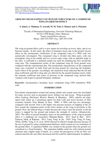
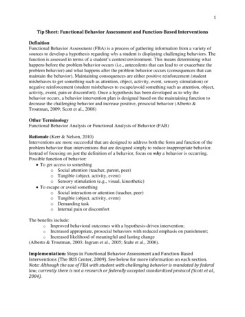
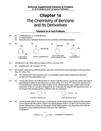
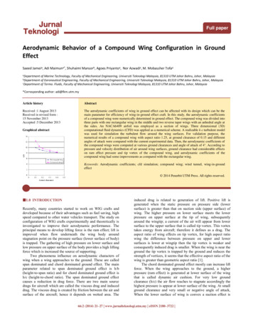
23Adi Maimun et al. / Jurnal Teknologi (Sciences & Engineering) 66:2 (2014), 21–27Table 1 Principal dimension of rectangular wing and compound wingswith different middle wing spanDimensionRectangularwingCompoundwingTotal wing span (b)250 mm250 mmRoot chord length (c)200 mm200 mmMiddle wing span (bm)-125Taper ratio (c/ct)-1.25Anhedral angle (a)-13 (a) Drag coefficient 3.0 EXPERIMENTAL PROCEDURES AND SET-UPIn the wind tunnel, aerodynamic force measurements werecarried out respect to ground clearances (h/c) and angles ofattacks (α). Ground clearance (h/c) was defined as the distanceratio between the wing trailing edge center and ground surface(h) to root chord length (c) of the wing. Figure 2 shows theexperimental setup of current experiment in the low speed windtunnel at the Universiti Teknologi Malaysia (UTM-LST).(b) Lift to drag ratioFigure 3 Comparison of experimental and numerical simulation resultsat ground clearance of 0.15, (a) Drag coefficient, (b) Lift to drag ratio 5.0 RESULTS AND DISCUSSIONS5.1 Pressure and Velocity ContoursFigure 2 Experimental setup in the low speed wind tunnel at theUniversiti Teknologi Malaysia 4.0TENDENCYOFNUMERICALEXPERIMENTAL SIMULATIONSANDIn this project, according to numerical and experimentalsimulations it can be seen that the results of both simulationshave similar trend. Figure 3a-b shows the aerodynamiccoefficients of the rectangular and the compound wings atground clearance of 0.15. The numerical results had somedeviations from experiments but both simulations show thecompound wings have some improvements in aerodynamicperformance compared to the rectangular wing at small groundclearance. Also, both simulations confirmed that dragcoefficient of compound wing was smaller that of therectangular wing at small ground clearance and angle of attackgreater than 2 , and lift to drag ratio of the compound wing wasgreater as well. It is important that the experiments validated theperformance of the compound wing where there are someimprovements at low ground clearances. In validation purpose,the experimental results confirmed the compound wing issuitable configuration to employ in WIG crafts for flying nearthe ground.Figures 4-9 show the pressure and velocity distribution ofcompound wing (Table 1) at ground clearances of 0.1 and 0.4with angle of attack of 4 . Figure 4 demonstrates the suctioneffect on the upper surface of compound wing at groundclearance of 0.1 is slightly stronger. There is a higher pressurenear leading edge of upper surface at ground clearance of 0.4that means the stagnation point is nearer to leading edge at thisheight (Figure 4b). The higher pressure distribution on lowersurface of the compound wing shows the pressure increased inlower side of the compound wing at ground clearance of 0.1(Figure 4a). At lower ground clearance, there is higher pressurein flow passage between lower side of compound wing andground at middle span as shown in Figures 5-6, also thestagnation point moves to lower side of compound wing aswing approaches to ground. Figures 7-8 depict higher velocityin flow passage under compound wing at ground clearance of0.4. The pressure distribution near wingtip of the compoundwing at ground clearance of 0.1 (Figures 9a) indicates that itstip vortices are gradual weaker compared to higher groundclearance (Figure 9b), therefore, the induced drag of thecompound wing droped when ground clearance was decreased.
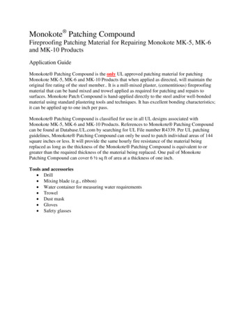
24Adi Maimun et al. / Jurnal Teknologi (Sciences & Engineering) 66:2 (2014), 21–27Upper surfaceLower surface(a) Compound wing (h/c 0.1)(a) Compound wing (h/c 0.1)(b) Compound wing (h/c 0.4)Figure 8 Velocity vector colored by velocity magnitude (m/s) on themiddle span of compound wing at ground clearances of 0.1 and 0.4 withangle of attack of 4 Upper surfaceLower surface(b) Compound wing (h/c 0.4)Figure 4 Pressure coefficient contour on upper and lower surface ofcompound wing at ground clearances of 0.1 and 0.4 with angle of attackof 4 (a) Compound wing (h/c 0.1)(b) Compound wing (h/c 0.4)Figure 9 Pressure coefficient distribution near wingtip of compoundwing at ground clearances of 0.1and 0.4 with angle of attack of 4 5.2 Lift Coefficient(a)Compound wing (h/c 0.1)(b) Compound wing (h/c 0.4)Figure 5 Pressure coefficient contour on the middle span of compoundwing at ground clearances of 0.1 and 0.4 with angle of attack of 4 (a) Compound wing (h/c 0.1)(b) Compound wing (h/c 0.4)The effect of different ground clearance on aerodynamiccoefficients of the rectangular wing and the compound wing(Table 1) at angle of attack of 4 is shown in Tables 2-6 andFigures 10-14. Figure 10 illustrates quick increase in the liftcoefficients of both wings as ground clearance was decreasedspecially at ground clearance lower than of 0.2. The compoundwing has a favorable enhancement where the plot of liftcoefficient of the compound wing is upper that of therectangular wing. According to the present results thedecreasing of ground clearance could improve considerably theram pressure on lower surface of the compound wing. Theincrement of lift coefficient of the compound wing comparedwith rectangular wing was calculated by Equation 4 andsummarized in Table 2. The increments have substantial valueat small ground clearance where at ground clearance of 0.1 is17.3%.Increment (%) Figure 6 Velocity vector colored by pressure coefficient on the middlespan of compound wing at ground clearances of 0.1 and 0.4 with angleof attack of 4 CL (Compound)CL (Re c tan gular)(4) 1Table 2 Lift coefficient and its increment versus ground clearance atangle of attack of 4º for rectangular wing and compound wingGroundclearance(a) Compound wing (h/c 0.1)(b) Compound wing (h/c 0.4)Figure 7 Velocity contour (m/s) on the middle span of compound wingat ground clearances of 0.1 and 0.4 with angle of attack of 4 0.10.150.20.30.4Lift coefficientRectangular wingCompound wingIncrementof CL 33717.34.00.4-3.0-4.2
25Adi Maimun et al. / Jurnal Teknologi (Sciences & Engineering) 66:2 (2014), 21–275.4 Lift to Drag RatioThe lift to drag ratio of the rectangular wing and the compoundwing (Table 1) versus ground clearance was summarized inTable 4, in addition, the increment of lift to drag ratio of thecompound wing was determined by Equation 6. The incrementof lift to drag ratio of the compound wing is noticeable at allground clearance as compared with the rectangular wing, forexample, at ground clearance of 0.1, this increment is 24.7%.The trend of lift to drag ratio of the compound wing and therectangular wing versus ground clearance is shown in Figure 12.The plot of the compound wing is upper especially at lowground clearance, that means the efficiency of the compoundwing significantly is higher that of the rectangular wing.Figure 10 Lift coefficient (CL) versus ground clearance at angle ofattack of 4 Increment (%) L / D(Compound)L / D(Re c tan gular))(6) 15.3 Drag CoefficientThe drag coefficients of the rectangular wing and the compoundwing (Table 1) versus ground clearance are depicted in Figure11; in addition the reduction of drag coefficient of thecompound wing was calculated by Equation 5 in Table 3. Figure11 reveals a small variation in the drag coefficient of both wingswith increase ground clearance; however, the drag coefficient ofthe compound wing had some fluctuation. The plot of thecompound wing is considerable lower that of the rectangularwing. The weaker tip vortex of the compound wing is mainreason of the reduction in its drag coefficient compared to therectangular wing. As mentioned before, smaller ground leveland area of the tip of the compound wing causes weaker tipvortex. The reduction of drag coefficient is between 5.9-8.6% asshown in Table 3.Re duction (%) 1 CD ( Compound)Table 4 Lift to drag ratio and its increment versus ground clearance atangle of attack of 4º for rectangular wing and compound wingGroundclearanceLift to drag ratioRectangularwingCompound wingIncrementof 7.80.38.428.946.20.48.138.291.9(5)CD (Re c tan gular)Table 3 Drag coefficient and its reduction versus ground clearance atangle of attack of 4º for rectangular wing and compound wingGroundclearance0.10.150.20.30.4Drag 0.0433Compound wingReductionof Figure 12 Lift to drag ratio (L/D) versus ground clearance at angle ofattack of 4 5.4 Moment Coefficient and Center of PressureFigure 11 Drag coefficient (CD) versus ground clearance at angle ofattack of 4 The variation of moment coefficients of the rectangular wingand the compound wing (Table 1) versus ground clearance isshown in Table 5 and Figure 13. A moment coefficient thatcauses a decreasing on angle of attack was defined as a positivemoment. The trend of moment coefficients in Figure 13indicates the increasing of ground clearance causes a drop inmoment coefficient and stability of the compound wing and therectangular wing, although the rate of this decline is higher forthe compound wing at low ground clearance. These differencesmostly could be related to pressure distribution of wing surfaceand subsequently center of pressure. The reduction of momentcoefficient of the compound wing was calculated by Equation 7in Table 5. This reduction is small at low ground clearance
26Adi Maimun et al. / Jurnal Teknologi (Sciences & Engineering) 66:2 (2014), 21–27where it is 3.2% at ground clearance of 0.1, however, itincreases rapidly by raising the ground clearance. In Table 6, thereduction of distance of center of pressure from leading edge ofthe compound wing was calculated by Equation 8, this reductionis between 7-8%. Based on present results the moving of thecenter of pressure of the compound wing and the rectangularwing is small with respect to variation of ground clearance asshown in Figure 14.Increment (%) 1 Re duction (%) 1 CM (Compound)(7)CM (Re c tan gular)X CP / c(Compound)(8)X CP / c(Re c tan gular)Table 5 Moment coefficient and its reduction versus ground clearanceat angle of attack of 4º for rectangular wing and compound wingGroundclearance0.10.150.20.30.4Moment 0Compoundwing0.0730.0610.0570.0520.047Reductionof CM (%)3.215.918.220.621.0Figure 14 Center of pressure (XCP/c) versus ground clearance at angleof attack of 4 6.0 CONCLUSIONThe aerodynamic characteristics of a compound wing werenumerically investigated. The compound wing is divided intothree parts; the middle part as the rectangular wing and two sideparts that are reverse taper wing with an anhedral angle. Theexcellent performance of compound wing was in small groundclearance (h/c 0.2). There was favorable increment of the liftcoefficient in small ground clearance, although, drag coefficienthad no more variation with ground clearance but lift to dragratio of compound wing had substantial improvement. At smallground clearance, there was high ram effect and low tip vortexfor the compound wing compared to the rectangular wing. Thereduction of moment coefficient of compound wing was fasterthat of the rectangular wing as ground clearance of wings wasdecreased. Also, the percentage of this reduction was higher forthe compound wing. Meanwhile, the position of center ofpressure of both compound and rectangular wings had smallfluctuation respect to ground clearance. The center of pressureof the compound wing was nearer to leading edge compared tothe rectangular wingAcknowledgementFigure 13 Moment coefficient (CM) versus ground clearance at angleof attack of 4 The authors would like to thank the Ministry of Science,Technology, and Innovation (MOSTI) Malaysia for funding thisresearch.Table 6 Center of pressure and its reduction versus ground clearance atangle of attack of 4º for rectangular wing and compound wingReferencesGroundclearanceCenter of pressureReduction ofXCP/c 0.3907.1[1][2]7.2[3][4][5][6]Abramowski, T. 2007. Numerical Investigation of Airfoil in GroundProximity. Journal of Theoretical and Applied Mechanics. 45(2): 425–436.Davis, J. E., and G. L. Harris. 1973. Nonplanar Wings in NonplanarGround Effect. Journal of Aircraft. 10(5): 308–312.Barrows, T. M. 1973. The Ram Air Cushion-advanced FluidSuspension for Tracked Levitated Vehicles. ASME 73-ICT-14.Widnall, S. E, and T. M. Barrows. 1970. An Analytic Solution for Twoand Three-Dimensional Wings in Ground Effect. Journal of FluidMechanics. 41(4): 769–792.Yang, W., Z. Yang, and C. Ying. 2010. Effects of Design Parameterson Longitudinal Static Stability for WIG craft. International Journal ofAerodynamics. 1(1): 97–113.Li, Y., W. Yang, and Z. Yang. 2010. Numerical Study on wing inGround Effect of Canard Configuration. Aeronautical ComputingTechnique. 40(4): 27–30.
27[7][8]Adi Maimun et al. / Jurnal Teknologi (Sciences & Engineering) 66:2 (2014), 21–27Li, Y., W. Yang, and Z. Yang. 2010. Numerical study on staticLongitudinal Stability of Canard WIG Craft. Flight Dynamics. 28(1):9–12.Lee, J., C. S. Han, and C. H. Bae. 2010. Influence of WingConfigurations on Aerodynamic Characteristics of Wings in GroundEffect. Journal of Aircraft. 47(3): 1030–1040.[9]Yang, W., and Z. Yang 2009. Aerodynamic Investigation of a 2DWing and Flows in Ground Effect. Chinese Journal of ComputationalPhysics. 26(2): 1–240.[10] Ying, C., W. Yang, and Z. Yang. 2010. Numerical Simulation onReverse Forward Swept Wing in Ground Effect. Computer AidedEngineering. 19(3): 35–39.
craft can fly in and out of ground effect with acceptable height static stability. This study tries to show the aerodynamic coefficients of a new compound wing configuration in ground effect. This compound wing is composed of three parts; a rectangular wing in the middle and two reverse taper wings with an anhedral angle at the sides.