Transcription
INSTALLATION INSTRUCTIONS600 CFM AND 1200 CFM IN-LINE BLOWERSFOR RANGE HOODSINSTRUCTIONS D'INSTALLATIONVENTILATEURS EN LIGNE AVEC DÉBIT DE 600 PI³ ET1200 PI³ POUR HOTTES D’ÉVACUATIONTable of Contents/Table des matièresIN-LINE BLOWER SAFETY.1INSTALLATION REQUIREMENTS .3Tools and Parts .3Location Requirements .3Venting Requirements .4Electrical Requirements .5INSTALLATION INSTRUCTIONS .6Prepare Location .6Make Electrical Connection .7ASSISTANCE OR SERVICE .9In the U.S.A.9In Canada .9WARRANTY.10SÉCURITÉ DU VENTILATEUR EN LIGNE.11EXIGENCES D’INSTALLATION.13Outils et pièces.13Exigences d’emplacement.13Exigences concernant l’évacuation .14Spécifications électriques .15INSTRUCTIONS D’INSTALLATION .16Préparation de l’emplacement.16Raccordement électrique.17ASSISTANCE OU SERVICE.19Au Canada.19GARANTIE.20IN-LINE BLOWER SAFETYYour safety and the safety of others are very important.We have provided many important safety messages in this manual and on your appliance. Always read and obey all safetymessages.This is the safety alert symbol.This symbol alerts you to potential hazards that can kill or hurt you and others.All safety messages will follow the safety alert symbol and either the word “DANGER” or “WARNING.”These words mean:DANGERWARNINGYou can be killed or seriously injured if you don't immediatelyfollow instructions.You can be killed or seriously injured if you don't followinstructions.All safety messages will tell you what the potential hazard is, tell you how to reduce the chance of injury, and tell you what canhappen if the instructions are not followed.IMPORTANT: READ AND SAVE THESE INSTRUCTIONS.FOR RESIDENTIAL USE ONLY.IMPORTANT : LIRE ET CONSERVER CES INSTRUCTIONS.POUR UTILISATION RÉSIDENTIELLE UNIQUEMENT.LI3ZDB/W10331013B
IMPORTANT SAFETY INSTRUCTIONSWARNING: TO REDUCE THE RISK OF FIRE, ELECTRICSHOCK, OR INJURY TO PERSONS, OBSERVE THEFOLLOWING: Use this unit only in the manner intended by themanufacturer. If you have questions, contact themanufacturer. Before servicing or cleaning the unit, switch power off atservice panel and lock the service disconnecting means toprevent power from being switched on accidentally. Whenthe service disconnecting means cannot be locked,securely fasten a prominent warning device, such as a tag,to the service panel. Installation work and electrical wiring must be done byqualified person(s) in accordance with all applicable codesand standards, including fire-rated construction. Do not operate any fan with a damaged cord or plug.Discard fan or return to an authorized service facility forexamination and/or repair. Sufficient air is needed for proper combustion andexhausting of gases through the flue (chimney) of fuelburning equipment to prevent backdrafting. Follow theheating equipment manufacturer's guideline and safetystandards such as those published by the National FireProtection Association (NFPA), the American Society forHeating, Refrigeration and Air Conditioning Engineers(ASHRAE), and the local code authorities. When cutting or drilling into wall or ceiling; do not damageelectrical wiring and other utilities. Ducted fans must always be vented outdoors.CAUTION: For general ventilating use only. Do not useto exhaust hazardous or explosive materials and vapors.CAUTION: To reduce risk of fire and to properly exhaustair, be sure to duct air outside - do not vent exhaust air intospaces within walls or ceilings, attics or into crawl spaces,or garages.WARNING: TO REDUCE THE RISK OF FIRE, USE ONLYMETAL DUCTWORK.WARNING: TO REDUCE THE RISK OF A RANGE TOPGREASE FIRE: Never leave surface units unattended at high settings.Boilovers cause smoking and greasy spillovers that mayignite. Heat oils slowly on low or medium settings. Always turn hood ON when cooking at high heat or whenflambeing food (i.e. Crepes Suzette, Cherries Jubilee,Peppercorn Beef Flambé). Clean ventilating fans frequently. Grease should not beallowed to accumulate on fan or filter. Use proper pan size. Always use cookware appropriate forthe size of the surface element.WARNING: TO REDUCE THE RISK OF INJURY TOPERSONS IN THE EVENT OF A RANGE TOP GREASEFIRE, OBSERVE THE FOLLOWING:a SMOTHER FLAMES with a close fitting lid, cookie sheet, ormetal tray, then turn off the burner. BE CAREFUL TOPREVENT BURNS. If the flames do not go outimmediately, EVACUATE AND CALL THE FIREDEPARTMENT. NEVER PICK UP A FLAMING PAN - you may be burned. DO NOT USE WATER, including wet dishcloths or towels a violent steam explosion will result. Use an extinguisher ONLY if:– You know you have a class ABC extinguisher, and youalready know how to operate it.– The fire is small and contained in the area where itstarted.– The fire department is being called.– You can fight the fire with your back to an exit.aBased on "Kitchen Fire Safety Tips" published by NFPA. WARNING: To reduce the risk of fire or electrical shock,do not use this fan with any solid-state speed controldevice.READ AND SAVE THESE INSTRUCTIONS2
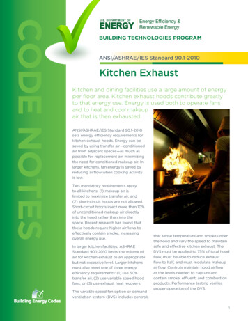
INSTALLATION REQUIREMENTSTools and PartsGather the required tools and parts before starting installation.Read and follow the instructions provided with any tools listedhere.Tools neededLocation RequirementsIMPORTANT: Observe all governing codes and ordinances.Have a qualified technician install the in-line blower motorsystem.All openings in the ceiling and wall where the in-line blower motorsystem will be installed must be sealed. Drill 1¼" (3 cm) drill bitFor Mobile Home Installations ³ ₁₆" (0.5 cm) drill bit Pencil Wire stripper or utility knife Tape measure or ruler PliersThe installation of this in-line blower motor system must conformto the Manufactured Home Construction Safety Standards, Title24 CFR, Part 328 (formerly the Federal Standard for Mobile HomeConstruction and Safety, Title 24, HUD, Part 280) or when suchstandard is not applicable, the standard for Manufactured HomeInstallation 1982 (Manufactured Home Sites, Communities andSetups) ANSI A225.1/NFPA 501A*, or latest edition, or with localcodes. Caulking gun and weatherproof caulking compound Vent clamps Jigsaw or keyhole saw Flat-blade screwdriver Metal snips Phillips screwdriverProduct DimensionsTop (outlet) view24³ ₄" (62.9 cm)7⁷ ₈"(20.0 cm)Parts needed ½" (1.3 cm) UL listed or CSA approved wiring conduit andconnectors 6 - 18 AWG wires, one each of the following colors: black,white, red, blue, gray, and green or green/yellow (ground)3³ ₈"(8.6 cm)12¹⁵ ₁₆"(32.9 cm)NOTE: The length of the conduit and 18 AWG wires isdetermined by the distance between the in-line blower motorand range hood terminal boxes. 11 - UL listed wire connectors ½" (1.3 cm) UL listed or CSA approved strain relief14¹¹ ₁₆"(37.3 cm)26¹ ₈" (66.4 cm)Parts suppliedRemove parts from packages. Check that all parts are included. 4 - 6.3 x 60 mm mounting screws 4 - flat washers 6-wire connector assembly for range hood 2 - strain relief connectors 1 - strain relief bushingBottom (inlet) view3³ ₈"(8.6 cm)16¹ ₈" (41.0 cm)7⁷ ₈"(20.0 cm)3
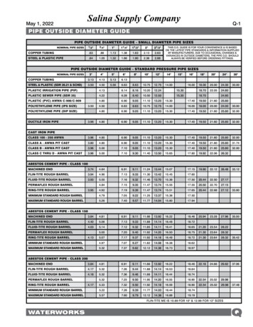
Venting Requirements The vent system must terminate to the outdoors. Do not terminate the vent system in an attic or other enclosedarea. Do not use 4" (10.2 cm) laundry-type vent or wall caps. Use round, metal vent only. Rigid metal vent isrecommended. Plastic or metal foil vent is not recommended. The length of the vent system and number of elbows shouldbe kept to a minimum to provide efficient performance.For the most efficient and quiet operation: Use no more than three 90 elbows. Make sure there is a minimum of 24" (61.0 cm) of straightvent between the elbows if more than 1 elbow is used. Do not install 2 elbows together. Use clamps to seal all joints in the vent system. The vent system must have a damper. Use weatherproof caulking to seal the exterior wall or roofopening around the cap. The size of the vent should be uniform.Typical In-line Blower System InstallationsA 10" (25.4 cm) round vent system is needed for installation (notincluded). The in-line blower system inlet and outlet openings are10" (25.4 cm) round. The exhaust (outlet) opening on the rangehood must also be 10" (25.4 cm) round.NOTE: Flexible vent is not recommended. Flexible vent createsback pressure and air turbulence that greatly reduceperformance.The vent system can terminate either through the roof or wall.NOTE: Plywood may be used as a mounting base to span openareas between ceiling joists and rafters. If used, be sure to useplywood capable of supporting the weight of the in-line blowersystem (50 lb [22.6 kg]).DECold weather installationsAn additional back draft damper should be installed to minimizebackward cold air flow and a thermal break should be installed tominimize conduction of outside temperatures as part of the ventsystem. The damper should be on the cold air side of the thermalbreak.The thermal break should be as close as possible to where thevent system enters the heated portion of the house.EABCMakeup airLocal building codes may require the use of makeup air systemswhen using ventilation systems greater than the specified CFM ofair movement. The specified CFM varies from locale to locale.Consult your HVAC professional for specific requirements in yourarea.4A. Mount on top of ceiling joists.B. Mount from cross-members tied to trusses.C. Duct horizontal, mount to cross-members tied to trusses.D. Mount on underside of rafters.E. Plywood
Calculating Vent System LengthElectrical RequirementsTo calculate the length of the system you need, add theequivalent feet (meters) for each vent piece used in the system.Vent PieceEquivalent Length45 elbow2.5 ft(0.8 m)90 elbow5.0 ft(1.5 m)The maximum equivalent vent lengths are:10" (25.4 cm) round vents - 60 ft (18.3 m)Example vent systemObserve all governing codes and ordinances.Ensure that the electrical installation is adequate and inconformance with National Electrical Code, ANSI/NFPA 70 (latestedition), or CSA Standards C22.1-94, Canadian Electrical Code,Part 1 and C22.2 No. 0-M91 (latest edition) and all local codesand ordinances.If codes permit and a separate ground wire is used, it isrecommended that a qualified electrician determine that theground path is adequate.A copy of the above code standards can be obtained from:National Fire Protection AssociationOne Batterymarch ParkQuincy, MA 02269CSA International8501 East Pleasant Valley RoadCleveland, OH 44131-5575 A 120 volt, 60 Hz., AC only, 15-amp, fused electrical circuit isrequired. 90 elbow6 ft (1.8 m)Wall capIf the house has aluminum wiring, follow the procedurebelow:1. Connect a section of solid copper wire to the pigtailleads.2. Connect the aluminum wiring to the added section ofcopper wire using special connectors and/or toolsdesigned and UL listed for joining copper to aluminum.Follow the electrical connector manufacturer's recommendedprocedure. Aluminum/copper connection must conform withlocal codes and industry accepted wiring practices.2 ft(0.6 m)The following example falls within the maximum recommendedvent length.1 - 90 elbow 5.0 ft (1.5 m)1 - wall cap 0.0 ft (0.0 m)8 ft (2.4 m) straight 8.0 ft (2.4 m)Length of system 13.0 ft (3.9 m) Wire sizes and connections must conform with the rating ofthe appliance as specified on the model/serial rating plate.The model/serial plate is located behind the filter on the rearwall of the range hood. Wire sizes must conform to the requirements of the NationalElectrical Code, ANSI/NFPA 70 (latest edition), or CSAStandards C22. 1-94, Canadian Electrical Code, Part 1 andC22.2 No. 0-M91 (latest edition) and all local codes andordinances.5
INSTALLATION INSTRUCTIONSPrepare Location Before making cutouts, make sure there is proper clearancewithin the ceiling or wall for the exhaust vent. When cutting or drilling into the ceiling or wall, do notdamage electrical wiring or other hidden utilities. Check that all installation parts have been removed from theshipping carton.5. Pull the spring clip to release the blower motor assembly.Remove the blower motor assembly from the housing andplace it on a covered surface.A1. Disconnect power.2. Determine which venting method to use: roof or wall exhaust.B CWARNINGExcessive Weight HazardUse two or more people to move and installrange hood.Failure to do so can result in back or other injury.DA. Front coverB. Blower mounting screwsC. Spring clipD. Motor electrical plug3. Using 2 or more people, move the in-line blower motorsystem to the mounting location.Prepare for Mounting the In-line Blower SystemThe in-line blower system must be fastened to a secure structureof the roof, ceiling, wall, floor, or new or existing frameconstruction. The 4 holes on either the inlet (bottom) side or theoutlet (top) side of the blower must be used to mount the in-lineblower system to the structure.NOTE: The mounting hole locations must span the studs.Additional stud framing may be required. Plywood may be usedto span open areas between ceiling joists or roof rafters to aidinstallation. This structure must be strong enough to support theweight of the in-line blower system (50 lb [22.6 kg] min).Installation of the In-line Blower SystemNOTE: The blower motor housing can be mounted using 4 holesfrom either the outlet side or the inlet side of the blower.Outlet Side:AAPrepare the In-line Blower SystemA1. Remove the 10 screws from the front cover of the in-lineblower motor housing and set them aside.2. Remove the front cover of the in-line blower motor housingand set it aside.NOTE: To make the blower motor housing easier to mount, theblower motor assembly can be removed. If you do not want toremove the blower motor assembly, proceed to the “Installationof the In-line Blower System” section.3. Disconnect the motor electrical plug from the blower motorassembly.4. Remove the screws that secure the blower motor assemblyto the in-line blower housing and set them aside.AA. Mounting holesInlet Side:AAA. Mounting holes1. Position the in-line blower motor housing in its mountinglocation and mark the 4 mounting hole locations.6
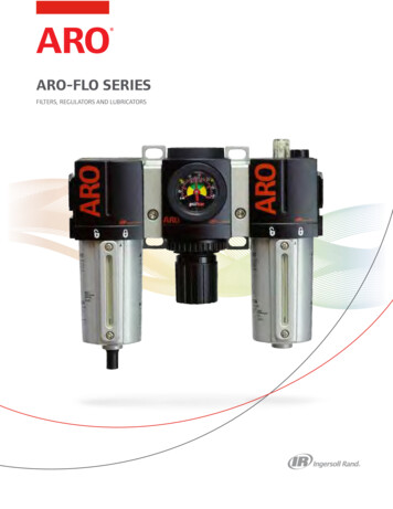
2. Drill 4 mounting pilot holes using a ³ ₁₆" (0.5 cm) drill bit.3. Attach the in-line blower motor housing to the mountinglocation with four 6.3 x 60 mm mounting screws andwashers.4. If removed, reinstall the blower motor assembly and secure itwith the screws previously removed.5. If removed, reattach the motor electrical plug to theconnector on the blower motor assembly.Make Electrical ConnectionWARNINGComplete Preparation1. Determine and make all necessary cuts for the vent system.IMPORTANT: When cutting or drilling into the ceiling or wall,do not damage electrical wiring or other hidden utilities.2. Determine the location where the ¹ ₂" (1.3 cm) wiring conduitwill be routed through the ceiling or wall.3. Drill a 1¹ ₄" (3.2 cm) hole at this location.4. Locate the electrical terminal boxes in the in-line blowerhousing and range hood (see the range hood installationinstructions). Remove the terminal box covers and set thecovers and screws aside.Electrical Shock HazardDisconnect power before servicing.Replace all parts and panels before operating.Failure to do so can result in death or electrical shock.Electrical Connection Inside In-line Blower System1. Disconnect power.2. Connect the wires from the wiring conduit to the wires fromthe motor electrical plug cable inside the in-line blowerhousing terminal box.BCDEFGHABAA. Electrical terminal boxB. Electrical knockoutI5. Remove the electrical knockout from the in-line blowerhousing and range hood (see the range hood installationinstructions) to prepare for the installation of the UL listed orCSA approved ¹ ₂" (1.3 cm) wiring conduit and conduitconnector.6. With the range hood mounted (see the range hood installationinstructions), run the ¹ ₂" (1.3 cm) wiring conduit between thein-line blower motor housing and the range hood. Pullenough ¹ ₂" (1.3 cm) wiring conduit to allow for easyconnection to the terminal boxes in the in-line blower housingand range hood.7. Run the six 18 AWG wires through the ¹ ₂" wiring conduit andconduit connectors and into the terminal boxes on the in-lineblower housing and range hood. Leave enough wire length ineach terminal box to make the wiring connections.8. Install the conduit connectors and conduit to the in-lineblower housing and range hood electrical terminal boxes.9. Connect the vent system to the range hood and in-line blowersystem and seal all joints with clamps.A. UL listed or CSA approved¹ ₂" wiring conduitB. UL listed wire connectorsC. Black wiresD. White wiresE. Red wiresF. Blue wiresG. Gray wiresH. Green (or yellow/green)and green/yellow wiresI. Motor electrical plug cable3. Use UL listed wire connectors and connect the black wires(C) together.4. Use UL listed wire connectors and connect the white wires(D) together.5. Use UL listed wire connectors and connect the red wires (E)together.6. Use UL listed wire connectors and connect the blue wires (F)together.7. Use UL listed wire connectors and connect the gray wires (G)together.7
WARNINGElectrical Shock HazardElectrically ground blower.Connect ground wire to green and yellow ground wirein terminal box.4. Run the wire ends from the 6-wire connector assemblythrough the ¹ ₂" (1.3 cm) strain relief, leaving enough wirelength to make the wiring connections. Tighten the strainrelief screws.5. Connect the wires from the 6-wire connector assembly to thewires from the wiring conduit inside the range hood terminalbox.6. Connect the same color wires to each other (black to black,white to white, etc.) using UL listed wire connectors.NOTE: Connect the green (or green/yellow) ground wire fromthe wiring conduit to the green (or bare) ground wire from thehome power supply using UL listed wire connectors (see the“Make Electrical Power Supply Connections to Range Hood”section in the range hood installation instructions).Failure to do so can result in death or electrical shock.BC8. Connect the green (or yellow/green) ground wire to thegreen/yellow ground wire (H) in the terminal box using ULlisted wire connectors.9. Reinstall the in-line blower terminal box cover and screw.10. Reinstall the front cover of the in-line blower housing andsecure it with 10 mounting screws.DEFGHAElectrical Connection Inside Range Hood Between In-lineBlower System and Range Hood1. With the range hood mounted (see the range hood installationinstructions), locate the wiring cable connector inside therange hood.2. Connect the 6-wire connector assembly supplied with thein-line blower motor system to the mating cable connectorfrom the range hood.3. Locate the terminal box inside the range hood and install a¹ ₂" (1.3 cm) UL listed or CSA approved strain relief (see therange hood installation instructions).8IA. UL listed or CSA approved¹ ₂" wiring conduitB. UL listed wire connectorsC. Black wiresD. White wiresE. Red wiresF. Blue wiresG. Gray wiresH. Green (or green/yellow)wireI. 6-wire connector assembly7. Connect the home power supply wiring to the range hoodfollowing the instructions that are supplied with the rangehood.8. Reinstall the range hood terminal box cover.9. Reconnect power.
ASSISTANCE OR SERVICEWhen calling for assistance or service, please know the purchasedate and the complete model and serial number of yourappliance. This information will help us to better respond to yourrequest.If you need replacement partsIf you need to order replacement parts, we recommend that youuse only factory specified parts. Factory specified parts will fitright and work right because they are made with the sameprecision used to build every new appliance. To locate factoryspecified replacement parts in your area, call us or your nearestdesignated service center.In the U.S.A.Call the Whirlpool Customer eXperience Centertoll free: 1-800-253-1301.Our consultants provide assistance with:For further assistanceIf you need further assistance, you can write to WhirlpoolCorporation with any questions or concerns at:Whirlpool Brand Home AppliancesCustomer eXperience Center553 Benson RoadBenton Harbor, MI 49022-2692Please include a daytime phone number in your correspondence.In CanadaCall the Whirlpool Canada LP Customer eXperience Centre tollfree: 1-800-807-6777.Our consultants provide assistance with: Features and specifications on our full line of appliances. Use and maintenance procedures. Features and specifications on our full line of appliances. Accessory and repair parts sales. Installation information. Use and maintenance procedures. Accessory and repair parts sales.Referrals to local dealers, repair parts distributors, andservice companies. Whirlpool Canada LP designated servicetechnicians are trained to fulfill the product warranty andprovide after-warranty service, anywhere in Canada. Specialized customer assistance (Spanish speaking, hearingimpaired, limited vision, etc.). Referrals to local dealers, repair parts distributors and servicecompanies. Whirlpool designated service technicians aretrained to fulfill the product warranty and provide afterwarranty service, anywhere in the United States.To locate the Whirlpool designated service company in yourarea, you can also look in your telephone directory YellowPages.For further assistanceIf you need further assistance, you can write to WhirlpoolCanada LP with any questions or concerns at:Customer eXperience CentreWhirlpool Canada LP200 - 6750 Century Ave.Mississauga, Ontario L5N 0B7Please include a daytime phone number in your correspondence.9
WHIRLPOOL CORPORATION MAJOR APPLIANCE WARRANTYLIMITED WARRANTYFor one year from the date of purchase, when this major appliance is operated and maintained according to instructions attached to orfurnished with the product, Whirlpool Corporation or Whirlpool Canada LP (hereafter “Whirlpool”) will pay for Factory Specified Partsand repair labor to correct defects in materials or workmanship. Service must be provided by a Whirlpool designated service company.This limited warranty is valid only in the United States or Canada and applies only when the major appliance is used in the country inwhich it was purchased. Outside the 50 United States and Canada, this limited warranty does not apply. Proof of original purchase dateis required to obtain service under this limited warranty.ITEMS EXCLUDED FROM WARRANTYThis limited warranty does not cover:1. Service calls to correct the installation of your major appliance, to instruct you on how to use your major appliance, to replace orrepair house fuses, or to correct house wiring or plumbing.2. Service calls to repair or replace appliance light bulbs, air filters or water filters. Consumable parts are excluded from warrantycoverage.3. Repairs when your major appliance is used for other than normal, single-family household use or when it is used in a manner that iscontrary to published user or operator instructions and/or installation instructions.4. Damage resulting from accident, alteration, misuse, abuse, fire, flood, acts of God, improper installation, installation not inaccordance with electrical or plumbing codes, or use of consumables or cleaning products not approved by Whirlpool.5. Cosmetic damage, including scratches, dents, chips or other damage to the finish of your major appliance, unless such damageresults from defects in materials or workmanship and is reported to Whirlpool within 30 days from the date of purchase.6. Any food loss due to refrigerator or freezer product failures.7. Costs associated with the removal from your home of your major appliance for repairs. This major appliance is designed to berepaired in the home and only in-home service is covered by this warranty.8. Repairs to parts or systems resulting from unauthorized modifications made to the appliance.9. Expenses for travel and transportation for product service if your major appliance is located in a remote area where service by anauthorized Whirlpool servicer is not available.10. The removal and reinstallation of your major appliance if it is installed in an inaccessible location or is not installed in accordancewith published installation instructions.11. Major appliances with original model/serial numbers that have been removed, altered or cannot be easily determined. This warrantyis void if the factory applied serial number has been altered or removed from your major appliance.The cost of repair or replacement under these excluded circumstances shall be borne by the customer.DISCLAIMER OF IMPLIED WARRANTIES; LIMITATION OF REMEDIESCUSTOMER'S SOLE AND EXCLUSIVE REMEDY UNDER THIS LIMITED WARRANTY SHALL BE PRODUCT REPAIR AS PROVIDEDHEREIN. IMPLIED WARRANTIES, INCLUDING WARRANTIES OF MERCHANTABILITY OR FITNESS FOR A PARTICULAR PURPOSE,ARE LIMITED TO ONE YEAR OR THE SHORTEST PERIOD ALLOWED BY LAW. WHIRLPOOL SHALL NOT BE LIABLE FORINCIDENTAL OR CONSEQUENTIAL DAMAGES. SOME STATES AND PROVINCES DO NOT ALLOW THE EXCLUSION OR LIMITATIONOF INCIDENTAL OR CONSEQUENTIAL DAMAGES, OR LIMITATIONS ON THE DURATION OF IMPLIED WARRANTIES OFMERCHANTABILITY OR FITNESS, SO THESE EXCLUSIONS OR LIMITATIONS MAY NOT APPLY TO YOU. THIS WARRANTY GIVESYOU SPECIFIC LEGAL RIGHTS, AND YOU MAY ALSO HAVE OTHER RIGHTS WHICH VARY FROM STATE TO STATE OR PROVINCETO PROVINCE.If outside the 50 United States and Canada, contact your authorized Whirlpool dealer to determine if another warranty applies.If you need service, first see the “Troubleshooting” section of the Use & Care Guide. After checking “Troubleshooting,” you may findadditional help by checking the “Assistance or Service” section or by calling Whirlpool. In the U.S.A., call 1-800-253-1301. In Canada,9/07call 1-800-807-6777.Keep this book and your sales slip together for futurereference. You must provide proof of purchase or installationdate for in-warranty service.Write down the following information about your major applianceto better help you obtain assistance or service if you ever need it.You will need to know your complete model number and serialnumber. You can find this information on the model and serialnumber label located on the product.Dealer nameAddressPhone numberModel numberSerial numberPurchase date10
SÉCURITÉ DU VENTILATEUR EN LIGNEVotre sécurité et celle des autres est très importante.Nous donnons de nombreux messages de sécurité importants dans ce manuel et sur votre appareil ménager. Assurez-vous detoujours lire tous les messages de sécurité et de vous y conformer.Voici le symbole d’alerte de sécurité.Ce symbole d’alerte de sécurité vous signale les dangers potentiels de décès et de blessures graves à vouset à d’autres.Tous les messages de sécurité suivront le symbole d’alerte de sécurité et le mot “DANGER” ou“AVERTISSEMENT”. Ces mots signifient :DANGERAVERTISSEMENTRisque possible de décès ou de blessure grave si vous nesuivez pas immédiatement les instructions.Risque possible de décès ou de blessure grave si vousne suivez pas les instructions.Tous les messages de sécurité vous diront quel est le danger potentiel et vous disent comment réduire le risque de blessure etce qui peut se produire en cas de non-respect des instructions.11
IMPORTANTES INSTRUCTIONS DE SÉCURITÉAVERTISSEMENT : POUR RÉDUIRE LE RISQUED'INCENDIE, CHOC ÉLECTRIQUE OU DOMMAGESCORPORELS, RESPECTER LES INSTRUCTIONSSUIVANTES : Utiliser cet appareil uniquement dans les applicationsenvisagées par le fabricant. Pour toute question, contacterle fabricant. Avant d'entreprendre un travail d'entretien ou de nettoyage,interrompre l'alimentation de la hotte au niveau du tableaude disjoncteurs, et verrouiller le tableau de disjoncteurspour empêcher tout rétablissement accidentel del'alimentation du circuit. Lorsqu'il n'est pas possible deverrouiller le tableau de disjoncteurs, placer sur le tableaude disjoncteurs une étiquette d'avertissement proéminenteinterdisant le rétablissement de l'alimentation. Tout travail d'installation ou câblage électrique doit êtreréalisé par une personne qualifiée, dans le respect desprescriptions de tous les codes et normes applicables, ycompris les codes du bâtiment et de protection contre lesincendies. Ne pas faire fonctionner un ventilateur dont le cordon ou lafiche est endommagé(e). Jeter le ventilateur ou le retournerà un centre de service agréé pour examen et/ou réparation. Une source d'air de débit suffisant est nécessaire pour lefonctionnement correct de tout appareil à gaz (combustionet évacuation des gaz à combustion par la cheminée), pourqu'il n'y ait pas de reflux des gaz de combustion. Respecterles directives du fabricant de l'équipement de chauffage etles prescriptions des normes de
8501 East Pleasant Valley Road Cleveland, OH 44131-5575 A 120 volt, 60 Hz., AC only, 15-amp, fused electrical circuit is required. If the house has aluminum wiring, follow the procedure below: 1. Connect a section of solid copper wire to the pigtail leads. 2. Connect the aluminum wiring to the added section of