Transcription
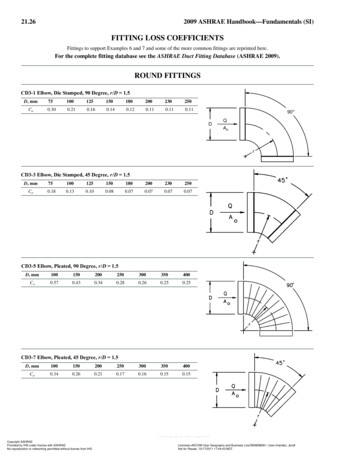
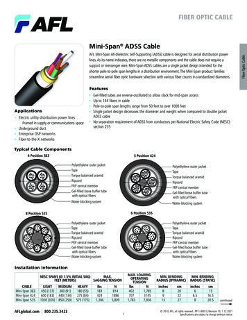
Dec-11 cab dr dsFITTING A REPLACEMENT DERAILLEUR CABLEAs a result of changes to the Brompton, different cables are required for different models: a long-wheel-base M-type bike (one shipped after January 2004, and with a main-frame hingewhich is cast) requires longer rear cables than a short-wheel-base M-type (where the hinge isforged, with a hand-brazed joint): M-types were formerly called L- or T-type. also, if the cable you are replacing is 4mm, without any fitted ferrules, this replacement cable with5mm ferrules will not fit the cable-stops: contact Brompton to obtain the correct cable stops (oralternatively carefully drill the bores of the cable-stops to 5mm). The P-type and H-type use the same cables. The M-type has its own cables as does the S-type.Make sure that you have the right length cable for the bike in question. The application sheetshows for which model this cable is suited.Remove the rear wheel: you may find that the summary instructions on the final page are a usefulguide (full details in the Owner Manual).subtext dr cab trig remDisconnecting cable at trigger. Move the derailleur lever up. Unscrew the screw holding thetrigger cap, and remove the cap. Lift the lever, with the cable still attached, away from the triggerhousing. Slacken the small grub screw in the threaded nipple TN where the cable is anchored (1.5mmhex key needed), and withdraw the cable: take care not to lose the threaded nipple, which can drop outthe moment the cable is withdrawn.subtext dr cab remDisconnecting the derailleur cable lower end.Down on the rear frame, fig DR25, the "dog-leg" DL should be left connected to the actuator(CHPUA, not shown in this view). If the dynamo wiring loom is attached to the derailleur cable, thenit needs to be disconnected by cutting the tiewraps (spares are supplied for reconnection later).It is a good idea to clean up the area where the derailleur cable ends, particularly the right handchainstay tube, and cable guide, this to avoid getting dirt into the cable on reassembly.With the cable disconnected from the lever, the next step is disconnection from the DL. The screwM6SS in the back of the DL has to be undone (4mm hex key), but before doing so, the pressureexerted on it by the inner spring, INS, acting through the cable nipple, CN, must be removed(otherwise the thread cut in the back of the DL may be damaged). To relieve this pressure, you haveto pull forwards on the inner cable, which compresses the spring. So, leaving the forward cable stop,CSTF, in place, move the outer cable forwards about 50mm, which exposes the inner cable: grip theinner cable with pliers at a position approx. midway along the cable guide CGR, and pull forwards afig DR25CGROSM6SSINSCNCSTFCSTRADLbit to compress the INS. Undo and remove the screw M6SS, and then allow the pliers and cable to
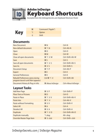
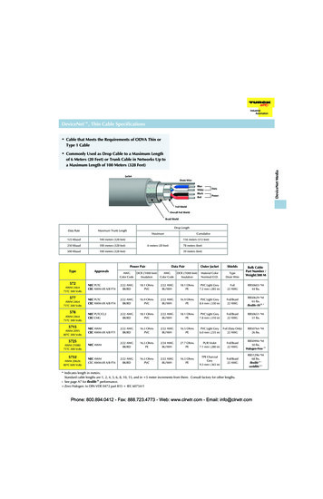
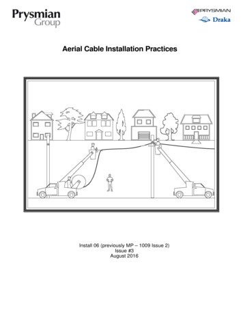
move rearwards till the spring is relaxed (note: if you intend retaining the inner cable, take care notto kink it with the pliers).Remove the inner cable.Remove the outer cable and fit the new one: the routingshould be exactly the same as for the original (fig CR1): infront of the handlebar, to the left of the h'bar stem, throughthe ring on CABGATH, through the CGC, inside the tubeTT, and outside the forward leg of the cable guide CGR. Thederailleur cable should lie below the other rear cable(s).figCR1CABGATHCGFsubtext dr cab fitConnecting the derailleur cable lower end.With the inner spring INS in place on the cable inner, feedthe cable inner through the back of the dog-leg DL, throughthe cable stops CSTRA and CSTF and up through the cableouter, until most of the spring has passed into the doglegand come to a stop. Move the outer cable forward so thatits rear end lies about 50mm in front of the forward cablestop CSTF (this last still in place in the loop on the rearcable guide CGR).BRCABRSSGCABTTCGCThe next step is to fit the screw M6SS to the back of theCGRdogleg, but first the inner spring INS has to be compressed.Carefully grip the exposed part of the inner cable with pliers, just in front of the CSTF, and pullforwards until the spring is compressed (with the cable nipple well inside the dogleg DL): feed thescrew in and do it up. Do not overtighten this screw but make sure that the underside of the crewhead touches the plastic dogleg DL.Slide the outer cable back till it engages inside the CSTF, right in till it comes to a stop.subtext dr cab trig fitConnecting the cable to the trigger.Note about overide spring. By design, the trigger moves the cable almost twice as faras is needed to effect the gear change: so, while the trigger is being pulled down, theactuator on the rear-frame will reach the low-gear position before the trigger is fullydown, the excess cable movement being absorbed by the overide spring at the bottomend of the cable. This means a) that, with the trigger up (high gear), it is OK to have alittle slack (up to about 3mm) in the cable, and b) that, as the cable stretches overtime, no cable-adjustment is needed. The procedure outlined below for connecting thecable will keep the initial slack to a minimum, so that as much as possible of thetrigger motion is reserved to cope with future cable stretch.figDR22GTFDown on the rear-frame, check that the two cable stops are pressed againstthe loop on the cable guide CGR, and that the cable outer is seating properly inits cable-stop. (If you have made any changes to the actuator (CHPUA), thehigh-gear stop screw should have been set.)Don't forget to fit the cable-stop GTF over the loose end of the cable first, fig DR22. Also (ifnecessary) slacken off the grub screw in the threadednipple TN far enough for the inner cable to passfig DR23through.Next, fig DR23, with the TN in place through the holein the lever (and the lever still out of the triggerhousing) feed the inner cable through the nipple TN atthe angle shown till the cable abuts the surface K on theGTFKFTN
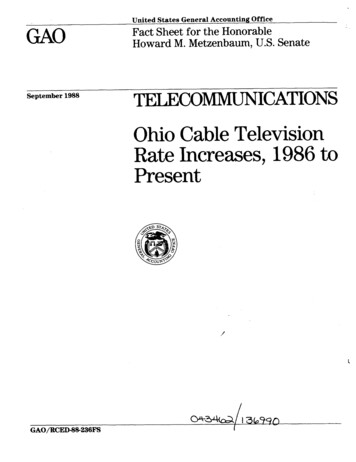
lever. Do up the screw in the nipple to secure the cable. [Note: if you allow more cable to extendpast the nipple than is allowed by surface K, this loose end will interfere with the free movement ofthe lever, and cause poor gear-changing.]Now, holding the cable-stop GTF in one hand and the lever in your other hand, pull the inner cableout a couple of times (taking care not to kink the cable). You will feel the resistance of the springs:this action should make sure that the cable ends and stops are all settled correctly in place.When assembling the lever into the trigger housing, the bike should be fully unfolded in order toset the cable correctly. This correct setting is obtained by fitting the ferrule GTF so that its flange Fengages one particular preferred slot of the four slots S, fig DR24, in the housing. To do this, fit thelever part-way onto its pivot (the raised boss), and then pull "gently" down (see note below) on theferrule, away from the lever: allow the lever to rotate antifigclockwise till it turns no further. At this stage decide whichDR24slot to fit the ferrule into: the correct slot is the one in linewith the flange F, or else the next available slot nearer tothe trigger-lever (i.e. such that the cable-inner becomesslightly slacker). Feed the lever fully into position on its pivotin the housing, and let the cable ferrule drop squarely intothe selected slot. Secure the trigger cap back into place,squeezing it together towards the housing where the cableenters.Note: when putting a pre-load onto the cable, this must be agentle pre-load only, to take up the slack without movingthe inner relative to the outer, i.e. a load just sufficient tomake sure that the cable outer abuts properly against itsstops.SIf an appropriate slot for the GTF cannot be found, thecause may be a) that the cable outer is not seating correctly in the CSTF or in the GTF, b) that theCSTF is not bearing against the loop in the CGR, or else c) that the cable supplied is the wronglength (the inner (excluding the nipple) should be 124mm longer than the outer).Checking that the cable is set OK in the trigger.fig DR2Operate the trigger a few times, and move it back to theUP position. The actuator CHPUA should be fully "out",with the stop-screw H contacting the surface SH of theSH"wing plate": if it isn't in contact, then the cable is tooSLtight, and the ferrule GTF needs to be moved up a slotin the trigger. Also check for play in the cable: grasp thecable outer just where it comes out of the trigger and pull it up and down, but not hard enough tomove the CHPUA: if there is more than 3mm of slack, then the ferrule GTF needs to be moveddown a slot. A further check is to move the trigger slowly down from the up position: the CHPUAshould complete its movement to the inner, low-gear position well before the trigger has latcheddown.If the bike has a wiring loom which has been detached from the derailleur cable, use the tiewrapssupplied to re-attach it. The rearmost tiewrap must be aft of the CGC, not in front.Fit the rear wheel and chain tensioner. For bikes with hub gears, reconnect the hub-gear control.Check the derailleur adjustment. Details elsewhere in these notes.
subtext gadj drDERAILLEUR ADJUSTMENT.After any changes or maintenance on the rear frame fittings or wheel, the settings should bechecked. With a new chain pusher, thederailleur stop screws must be adjusted.DLYou should also be aware that, forsatisfactory gear changes and smoothrunning, apart from these stop screws,two key elements of the system have tomove freely: the actuator (or "chainpusher"), and both idlers on the chaintensioner.HM3Lfig DR9Chain pusher adjustment.Use the stop screws, fig DR9, on the chainpusher. The idea is that, in high gear, the innerface of the inner upright IU, fig DR16, shall be asclose as possible to the idler wheel, without anyfig DR16rubbing pressure while the idler rotates (to giveIUthe slickest change with minimum wear): whenthe setting is right, you should just be able to see daylight between the two while turning the cranksforwards, perhaps with occasional contact. Use a2mm hex key in the forward stop screw H foradjustment.The same principle applies for the lower gearsetting, only this time, fig DR17, the inner faceof the outer upright OU has to just not rub onthe idler, and the rear stop screw L is used foradjustment.OUfig DR17Cable adjustment should seldom benecessary, as the trigger moves the cable twice as far as the movement of the chain-pusher (an override spring inside the dogleg DL absorbs this movement).Derailleur trouble shooting.If the derailleur still malfunctions after adjustment, or if turning the adjustor screws has no usefuleffect, and there is no obvious sign of dirt obstructing free movement, then the procedure fordiagnosis is as follows. Step 1, remove the chain tensioner: this allows you to identify whether theproblem lies with the idlers on the chain tensioner (they should be free to move in and out 7mm) orwith the chain-pusher. If the chain-pusher does not move freely, and the cause is not obvious, tryslackening the M3 screw slightly (there is supposed to be clearance). Step 2, remove this M3 screwcompletely: this allows you to identify whether there is a problem with the cable and the dogleg linkDL (e.g. dirt on the spring, misalignment of cable and cable stops, etc.), or with the chain-pusher (e.g.hidden dirt, seized bearing: you may need to remove the chain pusher from the frame).
SUMMARY OF DERAILLEUR CABLE CHANGE.1. Remove rear wheel.2. Disconnect the cable at the trigger. Take care not to lose the small parts here.3. Down on the rear frame, move the outer cable forward to expose the inner cable.4. Undo and remove the M6 set-screw (3mm hex key) at the back of the "dog-leg", but, toavoid damage to the threads while doing this, relieve the spring pressure by gripping theinner cable with pliers and pulling forwards.5. Check that the actuator is rotating freely between its stops (now's the time to rectify ifthere's a problem).6. Remove old cables and fit the new ones (the inner cable passing through the overide spring).Route the outer cable the same as originally, but, temporarily, leave some of the inner cableexposed at the lower end.7. Fit the set-screw back in the dog leg, again gripping the inner cable (with care to avoiddamage) and pulling forwards to compress the spring. Do not overtighten the set screw: itshould end up recessed in the dog-leg by about 2mm.8. Move the outer cable backwards to engage in the cable stop.9. Connect the top end of the inner cable to the lever, but don't forget to have the cableferrule in place on the outer cable first. While clamping the inner cable in the threadednipple, the cable end should abut the special "step" in the lever moulding.10. Fit the lever to the trigger, selecting the correct slot for the ferrule, and fit the cap to thetrigger.11. Check that the cable setting is OK.12. Fit the rear wheel and check function, finally resetting stop(s) if needed.subtext rw summaryREAR WHEEL – SUMMARY OF PROCEDURE FOR REMOVAL AND REFITTING.Removal:1. Move gear-trigger(s) up to high, and pedal forward & back to engage the high gear(s)2. If the bike has a hub-gear, disconnect the gear-indicator-chain from the cable-anchorage, unscrewthe gear-indicator-rod and withdraw the rod from inside the axle.3. Remove the chain-tensioner as follows: unhook drive-chain from swinging arm, undo chaintensioner nut, and withdraw the chain tensioner.4. Slacken off the main axle-nuts and remove wheel (if tab-washers are stuck, they will normallycome loose if you tap the wheel gently from side to side). To get the tyre past the brake blocks,either deflate the tyre or remove the LH brake block.Re-fitting (with hub-gears, make sure that the tab-washers engage correctly in axle-plate):1. With the chain in place over the (outer) sprocket, drop the axle into the axle-plates (the correctway round if it has “handed” tab-washers).2. Make sure the drive-chain isn’t trapped, and secure the wheel nuts over the washers.3. Fit the chain-tensioner (with a derailleur, the fixed-idler-wheel must lie between the two plates ofthe actuator). Secure using the chain-tensioner-nut and washer, but don’t overtighten the nut.4. Feed the chain over the idler-wheels on the chain-tensioner, and check chain flow.5. For hub-gears, if present:a. screw the gear-indicator-rod right into the axle, backing off not more than half a turn toalign it, and connect gear-indicator-chain to the cable-anchorage.b. Adjust the gears and make sure that all 3 gears are engaging OK.6. For derailleaur gears, if present, check function and adjust with M4 grub-screws in actuator ifnecessary.7. If you removed a brake-pad, re-fit it.Full details for wheel removal and re-fitting are in the Owner’s Manual.
subtext dr cab trig rem Disconnecting cable at trigger. Move the derailleur lever up. Unscrew the screw holding the trigger cap, and remove the cap. Lift the lever, with the cable still attached, away from the trigger housing. Slacken the small grub screw in the threaded nipple TN where the cable is anchored (1.5mm