Transcription
Owner’s Manual & Safety InstructionsSave This Manual Keep this manual for the safety warnings and precautions, assembly,operating, inspection, maintenance and cleaning procedures. Write the product’s serial number in theback of the manual near the assembly diagram (or month and year of purchase if product has no number).Keep this manual and the receipt in a safe and dry place for future reference.EASY FLUX12556355Visit our website at: http://www.harborfreight.comEmail our technical support at: productsupport@harborfreight.comWhen unpacking, make sure that the product is intactand undamaged. If any parts are missing or broken,please call 1-888-380-0318 as soon as possible.Copyright 2019 by Harbor Freight Tools . All rights reserved.No portion of this manual or any artwork contained herein may be reproduced inany shape or form without the express written consent of Harbor Freight Tools.Diagrams within this manual may not be drawn proportionally. Due to continuingimprovements, actual product may differ slightly from the product described herein.Tools required for assembly and service may not be included.Read this material before using this product.Failure to do so can result in serious injury.SAVE THIS MANUAL.19j
table of contentsSaFEtySafety . 2Specifications . 7Setup . 8Basic Welding . 12Welding Tips . 20Maintenance . 24Parts List and Diagram . 27Warranty . 28WaRning SyMBOlS and dEFinitiOnSThis is the safety alert symbol. It is used to alert you to potentialpersonal injury hazards. Obey all safety messages thatfollow this symbol to avoid possible injury or death.Indicates a hazardous situation which, if not avoided,will result in death or serious injury.SEtupIndicates a hazardous situation which, if not avoided,could result in death or serious injury.Indicates a hazardous situation which, if not avoided,could result in minor or moderate injury.Addresses practices not related to personal injury.BaSic WEldingiMpORtant SaFEty inFORMatiOnRead all safety warnings and instructions.Failure to follow the warnings and instructions may result in electric shock, fire and/or serious injury.Save all warnings and instructions for future reference.general SafetypROtEct yourself and others. Read and understand this information.WElding tipS1. Before use, read and understandmanufacturer′s instructions,Material Safety Data Sheets (MSDS′s),employer′s safety practices, and ANSI Z49.1.2. Keep out of reach of children.Keep children and bystanders away while operating.3. place the welder on a stable location before use.If it falls while plugged in, severe injury,electric shock, or fire may result.4. do not overreach.Keep proper footing and balance at all times.MaintEnancEPage 25. Stay alert, watch what you are doing and usecommon sense when operating a welder.do not use a welder while you are tired or underthe influence of drugs, alcohol or medication.A moment of inattention while operating weldersmay result in serious personal injury.6. avoid unintentional starting. Make sure you areprepared to begin work before turning on the Welder.7. never leave the Welder unattended whileenergized. Turn power off if you have to leave.8. the warnings, precautions, and instructionsdiscussed in this instruction manual cannotcover all possible conditions and situationsthat may occur. It must be understood by theoperator that common sense and caution arefactors which cannot be built into this product,but must be supplied by the operator.For technical questions, please call 1-888-380-0318.Item 56355
SaFEtyFume and gas SafetyINHALATION HAZARD:Welding and plasma cutting produce toxic fumes. Ulcers Damage to the reproductive organs Inflammation of the small intestine or stomach Kidney damage Respiratory diseases such asemphysema, bronchitis, or pneumoniaUse natural or forced air ventilation and weara respirator approved by NIOSH to protectagainst the fumes produced to reduce therisk of developing the above illnesses.6. Have a recognized specialist inindustrial Hygiene or Environmental Servicescheck the operation and air qualityand make recommendationsfor the specific welding situation.Follow OSHA guidelines forPermissible Exposure Limits (PEL’s) andthe American Conference of GovernmentalIndustrial Hygienists recommendations forThreshold Limit Values (TLV’s) for fumes and gases.2. do not use near degreasing orpainting operations.arc Ray SafetyaRc RayS can injure eyes and burn skin.1. Wear anSi-approved welding eye protectionfeaturing at least a number 10 shade lens rating.2. Wear leather leggings, fire resistant shoesor boots during use. Do not wear pants withcuffs, shirts with open pockets, or any clothingthat can catch and hold molten metal or sparks.3. Keep clothing free of grease, oil,solvents, or any flammable substances.Wear dry, insulating gloves and protective clothing.Item 563554. Wear an approved head covering to protectthe head and neck. Use aprons, cape, sleeves,shoulder covers, and bibs designed andapproved for welding and cutting procedures.5. When welding/cutting overhead or in confinedspaces, wear flame resistant ear plugs orear muffs to keep sparks out of ears.For technical questions, please call 1-888-380-0318.Page 3SEtup5. Work in a confined area only if itis well-ventilated, or while wearingan air-supplied respirator. Heart diseaseBaSic WElding4. use enough ventilation, exhaust at arc, orboth, to keep fumes and gases from breathingzone and general area. If engineering controlsare not feasible, use an approved respirator.WElding tipS Early onset of Parkinson’s Disease3. Keep head out of fumes.Do not breathe exhaust fumes.MaintEnancE1. Exposure to welding or cutting exhaustfumes can increase the risk of developingcertain cancers, such as cancer of thelarynx and lung cancer. Also, some diseasesthat may be linked to exposure to weldingor plasma cutting exhaust fumes are:
Electrical SafetyElEctRic SHOcK can Kill.SaFEty1. turn off, disconnect power, anddischarge electrode to ground before settingdown torch/electrode holder and before service.6. do not expose welders to rain or wet conditions.Water entering a welder will increasethe risk of electric shock.2. do not touch energized electrical parts.Wear dry, insulating gloves. Do not touch electrodeholder, electrode, welding torch, or welding wire withbare hand. Do not wear wet or damaged gloves.7. do not abuse the cord. never use the cordfor carrying, pulling or unplugging the welder.Keep cord away from heat, oil, sharp edgesor moving parts. Damaged or entangledcords increase the risk of electric shock.3. connect to grounded, gFci-protectedpower supply only.4. do not use near water or damp objects.SEtup5. people with pacemakers should consult theirphysician(s) before use. Electromagnetic fieldsin close proximity to heart pacemaker could causepacemaker interference or pacemaker failure.8. do not use outdoors.9. insulate yourself from the workpiece andground. Use nonflammable, dry insulatingmaterial if possible, or use dry rubber mats,dry wood or plywood, or other dry insulatingmaterial large enough to cover your fullarea of contact with the work or ground.BaSic WEldingFire SafetyaRc and HOt Slag can cause fire.1. clear away or protect flammable objects.Remove or make safe all combustible materials for aradius of 35 feet (10 meters) around the work area.Use a fire resistant material to coveror block all open doorways, windows,cracks, and other openings.WElding tipS2. Keep aBc-type fire extinguisher nearwork area and know how to use it.3. Maintain a safe working environment.Keep the work area well lit.Make sure there is adequatesurrounding workspace. Keep the work area freeof obstructions, grease, oil, trash, and other debris.MaintEnancE4. do not operate welders in atmospherescontaining dangerously reactive orflammable liquids, gases, vapors, or dust.Provide adequate ventilation in work areasto prevent accumulation of such substances.Welders create sparks which may ignite flammablesubstances or make reactive fumes toxic.Page 45. if working on a metal wall, ceiling, etc.,prevent ignition of combustibles on theother side by moving the combustibles to asafe location. If relocation of combustibles isnot possible, designate someone to serve asa fire watch, equipped with a fire extinguisher,during the cutting process and for at least onehalf hour after the cutting is completed.6. do not weld or cut on materials havinga combustible coating or combustibleinternal structure, as in walls or ceilings, withoutan approved method for eliminating the hazard.7. do not dispose of hot slag in containersholding combustible materials.8. after welding, make a thorough examinationfor evidence of fire. Be aware that easilyvisible smoke or flame may not be presentfor some time after the fire has started.9. do not apply heat to a container that has heldan unknown substance or a combustiblematerial whose contents, when heated,can produce flammable or explosive vapors.Clean and purge containers before applying heat.Vent closed containers, including castings,before preheating, welding, or cutting.For technical questions, please call 1-888-380-0318.Item 56355
2. disconnect the plug from the powersource before making any adjustments,changing accessories, or storing welders.Such preventive safety measures reduce therisk of starting the welder accidentally.3. prevent unintentional starting.Ensure the switch is in the offposition before connecting to powersource or moving the welder. Carryingor energizing welders that have theswitch on invites accidents.4. Store idle welders out of the reach ofchildren and do not allow persons unfamiliarwith the welder or these instructions tooperate the welder. Welders are dangerousin the hands of untrained users.5. use the welder and accessories inaccordance with these instructions, takinginto account the working conditions andthe work to be performed. Use of the welderfor operations different from those intendedcould result in a hazardous situation.6. do not use the welder for pipe thawing.SEtup1. do not use the welder if the switch does not turnit on and off. Any welder that cannot be controlledwith the switch is dangerous and must be repaired.SaFEtyWelder use and care2. Have your welder serviced by a qualifiedrepair person using only identicalreplacement parts. This will ensure thatthe safety of the welder is maintained.3. Maintain labels and nameplates on the Welder.These carry important information.If unreadable or missing, contactHarbor Freight Tools for a replacement.4. unplug before maintenance. Unplug the Welderfrom its electrical outlet before any inspection,maintenance, or cleaning procedures.WElding tipS1. Maintain welders. check for misalignment orbinding of moving parts, breakage of partsand any other condition that may affect thewelder’s operation. if damaged, have thewelder repaired before use. Many accidentsare caused by poorly maintained welders.BaSic WEldingMaintenanceMaintEnancESaVE tHESE inStRuctiOnS.Item 56355For technical questions, please call 1-888-380-0318.Page 5
groundingSaFEtytO pREVEnt ElEctRic SHOcK and dEatHFROM incORREct gROunding WiRE cOnnEctiOn:check with a qualified electrician if you are in doubt as to whether the outlet isproperly grounded.do not use the Welder if the power cord or plug is damaged. if damaged, have it repaired by a servicefacility before use. if the plug will not fit the outlet, have a proper outlet installed by a qualified electrician,do not use adapter plugs.SEtup1. The green wire inside the cord is connected tothe grounding system in the Welder. The greenwire in the cord must be the only wire connectedto the Welder’s grounding system and mustnever be attached to an electrically “live” terminal.Never leave the grounding wire disconnectedor modify the Power Cord Plug in any way.2. Make sure the tool is connected to an outlet havingthe same configuration as the plug. If the tool mustbe reconnected for use on a different type of electriccircuit, the reconnection should be made by qualifiedservice personnel; and after reconnection, the toolshould comply with all local codes and ordinances.Extension cordsBaSic WEldingdo not use an extension cord on this Welder.Replacement cords1. use only the supplied power cord for thisWelder or an identical replacement cord.2. do not install a thinner or longercord on this Welder.3. do not patch cords of any lengthtogether for this item. patches may allowmoisture to penetrate the insulation,resulting in electric shock.WElding tipSMaintEnancEPage 6For technical questions, please call 1-888-380-0318.Item 56355
SymbologyOverheat Shutdown IndicatorSaFEtyAmerican Wire GaugeElectric Shock Hazard.Do not touch energized parts.Torch CableInhalation Hazard.Keep head out of fumesand use proper ventilation.Cooling FanRead manual beforesetup and/or use.Housing Ground PointVacaOcVKVaInches Per MinuteFire Hazard.Keep flammable materialsaway during welding. Spattercan cause accidental fires.Volts Alternating CurrentAmperesArc Ray Hazard.Wear welding helmet withproperly rated filter lens.Open Circuit VoltageKilovolt Amperes(Volts / 1000 * Amperes)Pacemaker Hazard.Welding processes mayinterfere with pacemakers.Consult doctor before use.SEtupWorkpiece Ground CableipMaWgBaSic WEldingWire Feed (Speed)Specificationscurrent inputWelding current RangeRated duty cycleOpen circuit VoltageWire SpeedWelding Wire capacity23 A30 –125 A30% @ 90 A42 V60 – 200 IPM0.030" / 0.035" Flux Cored2 lb spoolMaintEnancEWire Spool capacity120 VAC / 60 HzWElding tipSpower inputItem 56355For technical questions, please call 1-888-380-0318.Page 7
SetupRead the EntiRE iMpORtant SaFEty inFORMatiOn section at the beginning of this manualincluding all text under subheadings therein before set up or use of this product.SaFEtytO pREVEnt SERiOuS inJuRy FROM accidEntal OpERatiOn:turn the power Switch off and unplug the Welder before setup.note: Remove the protective foam and cardboard from the Welder before setup.Wire Spool Installation / Wire SetuppowerSwitch1. turn the power Switch OFF and unplugthe Welder before proceeding.SEtupdoorBaSic WEldingdoorlatch2. Push back on the Door Latch,then open the Door.SpoolKnobSpringWElding tipS3. Remove the Spool Knob, Spring, andSpool Plate. Remove the old Spool andall remaining wire from the intEnancE4. Place the new Wire Spool over the Spool Spindleas illustrated.to prevent wire feed problems, set the Spoolso that it will unwind counterclockwise.5. Replace the Spool Plate and Springover the Spool Spindle and secureSpool in place with the Spool Knob.notice: If Wire Spool can spin freely, Spool Knob is tooloose. This will cause the welding wire to unravel andunspool which can cause tangling and feeding problems.Page 8Wire must unwindin this directionFor technical questions, please call 1-888-380-0318.Item 56355
Feed tensioneridler arm6. Turn the Feed Tensioner knob counterclockwise toloosen it enough to pull it down to remove tension.The spring-loaded Idler Arm will move up as shown.03.030″SaFEty0″7. Feed Roller instructions:Check that the Feed Roller is turned to properlymatch the wire size marked on the Wire Spool:Feed RollerKnob.03SEtup0″aa. Twist the Feed Roller Knobcounterclockwise to release it.0″FeedRoller0.035V-groove0.030V-grooveb. Remove the Feed Roller Knob toexpose the Feed Roller.BaSic WElding.03Bc. Flip or replace the Feed Roller as neededand confirm that the number showing is thesame as the wire diameter on the Spool.WElding tipSc.030″dd. Twist the Feed Roller Knob back intoplace to secure the Feed Roller.03MaintEnancE0″Item 56355For technical questions, please call 1-888-380-0318.Page 9
iMpORtantSecurely hold onto the end of the welding wire and keeptension on it during the following steps.SaFEtyif this is not done, the welding wire will unravel and unspoolwhich can cause tangling and feeding problems.WireSpoolHOld WiRESEcuRElyFeedguide8. Cut off all bent and crimped wire.The cut end must have no burrs orsharp edges; cut again if needed.030″SEtup9. Keep tension on the wire and guide atleast 12 inches of wire into the WireInlet Liner and Feed Guide.10. Make sure the welding wire is resting in thegroove of the Feed Roller, then push the wireIdler Arm down, and swing the Feed Tensionerup to latch it across the tip of the arm.After the wire is held by the Tensioner,you may release it.WeldingWireWire inletlineridler armFeed tensioner.03.03BaSic WElding0″0″note: The tension should be 2 – 3.Too much force on flux-cored wire willcrush it and cause feeding issues.11. Unscrew the Contact Tipcounterclockwise and remove.12. Lay the Flux Gun Cable out in a straight line sothat the welding wire moves through it easily.Leave the cover open, so that the feedmechanism can be observed.WElding tipSWaRningThe following steps require applying power to the Welderwith the cover open.to prevent serious injury from fire or electric shock:1. do not touch anything, especially not the ground clamp,with the gun or welding wire or an arc will be ignited.2. do not touch internal Welder componentswhile it is plugged in.MaintEnancE13. Turn the Power Switch off and do not touch theGun’s Trigger and before connecting Power Cord:14. Plug the Power Cord into a properlygrounded, GFCI protected 120 VAC (20amp rated) receptacle that matches theplug and turn the Power Switch ON.powerSwitchnote: The circuit must be equipped withdelayed action-type circuit breaker or fuses.Page 10For technical questions, please call 1-888-380-0318.Item 56355
15. Point the Gun away from all objects.Press and hold the Cold Feed Switchuntil the wire feeds through theend of the Gun two inches.Flux gunthe wire liner may come out with the weldingwire. this is normal, just turn off the Welderand push the wire liner back into the gun.SaFEty2"WeldingWireIf the wire does not feed properly andthe Spool is stationary, turn OFF andunplug the Welder and slightly tighten theFeed Tensioner clockwise before retrying.SEtup16. To check the wire’s drive tension, press and holdCold Feed Switch to feed the wire against a pieceof wood from 2 to 3 inches away.If the wire stops instead of bending, unplugthe Welder, slightly tighten the Feed Tensionerclockwise, and try again. If the wire bends fromthe feed pressure, then the tension is set properly.incrementallyincrease tensionuntilwire bends.032–3"BaSic WElding0″17. Turn OFF the Power Switch and unplug thePower Cord from its electrical outlet.19. Slide the Nozzle onto the gun as well.contacttipFlux gunWElding tipS18. Select a Contact Tip that is compatible withthe welding wire used. Slide the ContactTip over the wire and thread it clockwise intothe Flux Gun. Tighten the Contact Tip.20. Cut the wire off at 1/2" from tip (1/2" stickout).doordoorlatchMaintEnancE21. Close the Door. Make sure Door is securely latched.Item 56355For technical questions, please call 1-888-380-0318.Page 11
Basic WeldingSaFEtyRead the EntiRE iMpORtant SaFEty inFORMatiOn section at the beginning of this manualincluding all text under subheadings therein before welding.tO pREVEnt SERiOuS inJuRy:protective gear must be worn when using the Welder; minimum shade number 10 full face shield(or welding mask), ear protection, welding gloves, sleeves and apron, NIOSH-approved respirator, and fireresistant work clothes without pockets should be worn when welding.light from the arc can cause permanent damage to the eyes and skin.do not breathe arc fumes.Flux-cored wire welding is used to weld mild steeland stainless steel without shielding gas.SEtupGood welding takes a degree of skill and experience.Practice a few sample welds on scrap beforewelding your first project. Additional practiceperiods are recommended whenever you weld: a different thickness of materiala different type of materiala different type of connectionusing a different process (MIG vs. Flux)BaSic WEldingMake practice welds on pieces of scrap to practicetechnique before welding anything of value.powerOnWElding tipStO pREVEnt SERiOuS inJuRy,FiRE and BuRnS:Keep welding tip clear of groundedobjects whenever unit is pluggedin and turned on. MaintEnancEpractice your weldingtechnique on scrappieces before weldinganything of value.Page 12For technical questions, please call 1-888-380-0318.Item 56355
SaFEtyFront panel 1BaSic WEldingWireSpeedKnobFlux gunJA10MaintEnancEgroundclampWElding tipSVoltageKnobSEtupEDItem 56355For technical questions, please call 1-888-380-0318.Page 13
interior controlsFeed tensioneridler armSaFEtyWireSpoolSpoolKnobSEtupWire inletlinerFeedRoller Knobcold FeedSwitchBaSic WEldingWeld SettingsRefer to the Settings Chart on the inside of the Welder door for Flux-Cored and MIG Weld settings.The chart is only intended to show general guidelines for different wire sizes and for differentthicknesses of material. The initial settings used at the beginning of a weld may need to beadjusted after stopping and carefully inspecting the weld. Proper welding takes experience.WElding tipSMaintEnancEPage 14For technical questions, please call 1-888-380-0318.Item 56355
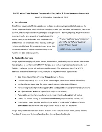
Duty Cycle (Duration of Use)For example, a welder with a 40% duty cycle at 90 Awelding current must be allowed to rest for at least6 minutes after every 4 minutes of continuous welding.Failure to carefully observe any duty cycle limitationscan easily over-stress a welder’s power generationsystem contributing to premature welder failure.SaFEtyavoid damage to the Welder by not weldingfor more than the prescribed duty cycle time.The Duty Cycle defines the number of minutes, within a10 minute period, during which a given welder canproduce a particular welding current without overheating.Rated Duty Cycle30% Use at 90 AFor 10 continuous allow the Welder to cool with thepower Switch on, so that the internalFan will help cool the Welder.concrete slab(or other heat-proof,non-conductive surface)powerSwitchMaintEnancEWhen the Overload Indicator is no longerlit and the Welder can be used again,use shorter welding periods and longerrest periods to prevent needless wear.Flux gunWElding tipSThis Welder has an internal thermal protectionsystem to help prevent this sort of over-stress.When the Welder overheats, it automaticallyshuts down and the Overload Indicator lights.The Welder automatically returns to serviceafter cooling off. Should this occur, rest theFlux Gun on an electrically non-conductive,heat-proof surface, such as a concreteslab, well clear of the ground clamp.7MinutesRestingBaSic WElding3MinutesWeldingItem 56355For technical questions, please call 1-888-380-0318.Page 15
Setting up the WeldSaFEty1. Make practice welds on pieces of scrap thesame thickness as your intended workpieceto practice technique before welding anythingof value. Clean the weld surfaces thoroughlywith a wire brush or angle grinder; theremust be no rust, paint, oil, or other materialson the weld surfaces, only bare metal.SEtup2. Use clamps (not included) to hold the workpiecesin position so that you can concentrate onproper welding technique. The distance(if any) between the two workpieces must becontrolled properly to allow the weld to holdboth sides securely while allowing the weldto penetrate fully into the joint. The edges ofthicker workpieces may need to be chamfered(or beveled) to allow proper weld penetration.clampsworkpiecescleansurfaces tobare metal.chamfer thick workpieces.notice: When welding equipment on a vehicle,disconnect the vehicle battery power from both thepositive connection and the ground before welding.This prevents damage to some vehicle electricalsystems and electronics due to the high voltageand high frequency bursts common in welding.BaSic WEldingWorkpiece3. Clamp Ground Cable to bare metal on theworkpiece near the weld area, or to metal workbench where the workpiece is clamped.WElding tipS4. Set the Wire Speed and Voltage Knobs tothe desired settings. Refer to the SettingsChart on the inside of the Welder door.groundclampEMaintEnancEPage 16FGDCHIBJA5note: The initial settings may need to be adjustedafter stopping and carefully inspecting the weld.Proper welding takes experience.cleansurface tobare metal.6478392110For technical questions, please call 1-888-380-0318.Item 56355
5. Turn the Power Switch off and do not touchthe Gun’s Trigger and before connectingPower Cord: Plug the Power Cord into aproperly grounded, GFCI protected 120 VAC(20 amp rated) receptacle that matches theplug and turn the Power Switch ON.SaFEtypowerSwitchnote: The circuit must be equipped withdelayed action-type circuit breaker or fuses.SEtuppowerSwitchMaintEnancEWElding tipSBaSic WElding6. Set Flux Gun down on nonconductive,nonflammable surface away from any groundedobjects. Turn the Power Switch ON.Item 56355For technical questions, please call 1-888-380-0318.Page 17
Basic Welding technique1. Press (and hold) Trigger and contact the areato be welded with electrode wire to ignite arc.SaFEtystringer beadweave bead2. For a narrow weld, you can usually draw the wire ina steady straight line.This is called a stringer bead.For a wider weld, draw the wire back and forthacross the joint.This is called a weave bead and takespractice to perform properly.SEtupWeld Flux gun angles,viewed from front of weld joint.3. Direct the welding wire straight into the joint. Thisgives an angle of 90 (straight up and down)for butt (end to end) welds, and an angleof 45 for fillet (T-shaped) welds.90 BaSic WElding45 fillet weld jointbutt weld jointdrag angle0-15 WElding tipS4. When using flux-cored wire, the end of theFlux Gun should be tilted so that wire isangled anywhere in-between straight onand 15 in the direction you are welding.The amount of tilt is called the drag angle.WelddirectionFlux-cored Wire5. The Contact Tip should remain within 1/2″of the work surface. This distance is calledCTWD - Contact Tip to Work Distance.ctWd(up to 1/2")MaintEnancEPage 18For technical questions, please call 1-888-380-0318.Item 56355
EFGDCH5647Flux gun8392110When the Overload Indicator is no longerlit and the Welder can be used again, useshorter welding periods and longer restperiods to help prevent needless wear.concrete slab(or other heat-proof,non-conductive surface)powerSwitch6. After welding the test weld on a pieceof scrap for a few seconds, stop, andcheck your progress. Clean, then compareyour weld’s appearance with the diagramsand descriptions in the Welding tips sectionstarting on the next page. After making anynecessary adjustments, continue to weldwhile carefully following the DUTY CYCLEguidelines as explained on page 15.SEtupallow the Welder to cool with thepower Switch on, so that the internalFan will help cool the Welder.OverloadindicatorJASaFEtyIBafter practice weldingfor a few seconds, StOpand examine your weldusing the guidelinesstarting on the next page.BaSic WEldingnote: If Welder is used too long, the OverloadIndicator lights up and the unit automaticallyshuts down. The Welder automatically returnsto service after cooling off. Should this occur,rest the Flux Gun on an electrically nonconductive, heat-proof surface, such as aconcrete slab, away from the ground clamp.cautiOn! Weld will be hot, do not touch.9. Remove Ground Clamp from workpieceor table and disconnect Flux Gun.10. Respool wire by clipping wire, removingcontact tip on Flux Gun, releasing Idler Armon Wire Feed mechanism, and rotating theWire Spool counterclockwise. Be sure tosecurely hold wire as it is being respooledbecause the end of wire has a tendency toquickly unravel once it clears the wire feeder.Item 56355concrete slabWElding tipS8. Allow Welder to cool down, thenunplug the Power Cord.Flux gun(or other heat-proof,non-conductive surface)powerSwitchFor technical questions, please call 1-888-380-0318.MaintEnancE7. When welding is complete, set theFlux gun down on a heat-proof, electricallynon-conductive surface.Turn the Power Switch OFF.Page 19
Welding tipsSaFEtyA good way to test welding technique is to examine aweld’s appearance after it has cooled and the slaghas been removed. Then, better welding can belearned by adjusting your weld technique to remedyany problems found.A typical flux-cored wire (FCAW) weldbefore cleaning.weld beadslagspatterbase metalcleaning the WeldSEtuptO pREVEnt SERiOuS inJuRy:continue to wear anSi-approvedsafety goggles and protective wearwhen cleaning a weld.Sparks or chips may fly when cleaning.BaSic WElding1. A weld from flux-cored wire will becovered by slag. Use a chipping hammerto knock this off. Be careful not todamage the weld or base material.chippingHammer2. Use a wire brush to further clean the weldor use an angle grinder (sold separately) toshape the weld.Wire BrushStrike testa test weld on a piEcE OF ScRap can be tested byusing the following procedure.WEaR anSi-appROVEd SaFEty gOgglESduRing tHiS pROcEduRE.clampdead-blow hammerScRapworkpieceWElding tipSWaRning! this test Will damage the weld it isperformed on. this test is Only an indicator of weldtechnique and is not intended to test working welds.gOOd WEldbends and is not brittle1. After two scraps have been welded together and theweld has cooled, clamp one scrap in a sturdy vise.2. Stay clear from underneath while you strikethe opposite scrap with a heavy hammer,preferably a dead-blow hammer.dead-blow hammerclampScRapworkpieceMaintEnancE3. A gOOd WEld will deform but not break,as shown on top.A pOOR WEld will be brittle and snap at the weld,as shown on bottom.pOOR WEldsnaps or cracksPage 20For technical questions, please call 1-888
Tools required for assembly and service may not be included. Read this material before using this product. Failure to do so can result in serious injury. SAVE THIS MANUAL. Page 2 For technical questions, please call 1-888-380-0318. Item 56355 Sa FE ty Maint E nanc E Ba S ic W E lding W E