Transcription
MAXIMA 2 OPERATOR’S MANUALThis guide has been prepared for the operator of Carrier Transicoldtrailer refrigeration units. It contains basic instructions for the dailyoperation of the refrigeration unit as well as safety information,troubleshooting tips, and other information that will help you todeliver the load in the best possible condition. Please take the timeto read the information contained in this booklet and refer to itwhenever you have a question about the operation of your CarrierTransicold unit.Your refrigeration unit has been engineered to provide long,trouble--free performance when it is properly operated andmaintained. The checks outlined in this guide will help to minimizeover--the--road problems.Maintenance program will also help to control operating costs,increase the unit’s working life, and improve performance.Carrier Transicold has an on--going product quality upgrade policy.As a result, specifications are liable to change without notice.2
CONTENTSPageUNIT IDENTIFICATIONSAFETYFEATURESMICROPROCESSOR CONTROLLERDESCRIPTIONPRE--TRIP INSPECTIONUNIT OPERATIONFAULT ALARM DISPLAYFUSESSOLID-STATE CONTROLLERDESCRIPTIONPRE--TRIP INSPECTIONUNIT OPERATIONFUSESTROUBLESHOOTINGUNIT MAINTENANCEUNIT MAINTENANCE SCHEDULEDESCRIPTION OF SERVICE REQUIREMENTSBELTSFILTERSPRODUCT LOADINGRECOMMENDED TRANSPORT TEMPERATURESSTANDBY OPERATION GUIDELINESMANUFACTURER INFORMATION“A.T.P. EUROPE” REGULATION EXTRACTEMERGENCY ROAD 525357593
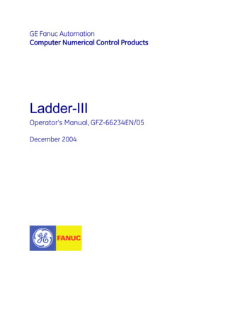
UNIT IDENTIFICATIONEach Maxima 2 refrigeration unit is identified by means of anameplate fastened to the unit. On the Maxima 2, this nameplateis inside the curb--side side door of the unit. This nameplateidentifies the complete model number of the unit, the serial number,the refrigerant charge and quantity, and the date the unit was placedin service.If a problem occurs, please refer to the information on this plate, andmake a note of the model and serial number before calling forassistance. This information will be needed when you contact atechnician or Carrier Transicold Service Engineer so that he or shemay properly assist you.4
UNIT IDENTIFICATIONGB5
SAFETYYour Carrier Transicold refrigeration unit has been designed with thesafety of the operator in mind. During normal operation, all movingparts are fully enclosed to help prevent injury. During all pre--tripinspections, daily inspections, and problem troubleshooting, youmay be exposed to moving parts; please stay clear of these movingparts when the unit is in operation and when the main power switchis in the Run (On) position.The evaporator and condenser are made of finned tubes. The finscan cause injury on contact with skin. It is recommended to wearprotective gloves during all handling operations.During operation, certain components such as the exhaust pipe,discharge outlet, and cooling circuit radiator can become extremelyhot. During routine service operations, wear protective gloves.WARNING : When the buzzer sounds the unit will start30 seconds later.AUTO START/STOP (OPTION FOR ELECTROMECHANICAL)Your refrigeration unit is equipped with Auto--Start/Stop, a valuablefuel--saving feature. When the unit is set for Auto--Start/Stopoperation it may start at any time and without warning. Whenperforming any check of the refrigeration unit (e.g. checking belttension, or the oil level), make sure that the main power switch is inthe Stop position.To ensure your unit is fitted with the START/STOP system, checkfor the presence of switch 16 (see page 25).ENGINE COOLANTThe engine, as with all diesel engines, is equipped with apressurized cooling system. Under normal operating conditions, thecoolant in the engine and radiator is under high pressure and is veryhot. Contact with hot coolant can cause severe burns. Do notremove the cap from a hot radiator; if the cap must be removed, doso very slowly in order to release the pressure without spraying.6
SAFETYREFRIGERANTSThe refrigerant contained in the refrigeration system of your unit cancause frostbite, severe burns, or blindness when in direct contactwith the skin or eyes. For this reason, and because of legislationregarding the handling of refrigerants during system service,whenever your unit requires service of the refrigeration system, werecommend that you contact your nearest Carrier Transicoldauthorized repair facility for service.BATTERYThis unit is equipped with a lead--acid type battery. The batterynormally vents small amounts of flammable hydrogen gas. Keepany flame, any lighted object (cigarette etc.) or any source of sparksaway from the battery elements. A battery explosion can causeserious physical harm and/or blindness.7GB
FEATURESThe Maxima 2 is equipped with a diesel engine and an electricmotor.If necessary, the unit can operate as a heater simply by using thethermostat: its control is the same as for the refrigeration cycle.The START/STOP system automatically cycles the unit on and offduring engine operation, regulating refrigeration or heating outputto meet the temperature requirements of the products beingtransported.- Diesel engine:Diesel -- 4 cylinders -- water--cooled -- reinforced crankshaftbearings -- perfect balance at all speeds -- low noise level -water--oil safety switch -- large--volume oil pan.- Electric motor :Multi--voltage- 4--stage thermostat :Four operating modes for temperature set--point --12 C: High--speed cool Low--speed cool Low--speed heat High--speed heatTwo operating modes for temperature set--point --12 C: High--speed cool Low--speed cool- Controller :The unit can be delivered fitted either with a microprocessorcontroller or solid--state controller.- Charge alternator Maxima 2 14 VDC, 50 AOPERATING PRINCIPLEThe operation of this self--contained unit is automatic.8
FEATURES- In Road mode (engine operation)The diesel engine runs continuously. During temperature pulldownit runs at high speed. Down to --12 C, the box temperature isregulated is in low--speed heat; under --12 C, a safety cut--outprevents any possibility of heating: this means that as soon as theset--point temperature has been reached the unit will run inlow--speed cool.NOTE: If a fixed negative temperature selection is required lowerthan --12 C (e.g. --15 C or --20 C or --25 C), please contact yourlocal Carrier dealer or service.- In Standby modeWITH START / STOPThe thermostat controls unit shut--down as soon as the set--pointtemperature has been reached.WITHOUT START / STOPThe unit will run continuously :cool / heat for setpoint above --12 Conly cool for setpoint below --12 C- DefrostThe unit is equipped with an automatic defrost.Triggering of the defrost cycle is controlled by a differential pressureair switch; shut--down of the defrost cycle is controlled by twodefrost termination thermostats. The defrost cycle can also becontrolled manually. During the defrost cycle the evaporator bloweris off.9GB
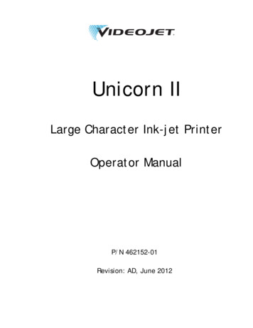
MICROPROCESSOR CONTROLLERDESCRIPTIONThe microprocessor controlled features of this unit provide the mostreliable control system currently available. It is also designed to bethe easiest to use, offering great flexibility in control, yet minimaluser input for normal operation -- a true “set it and forget it” design.(1)(2)(3)DISPLAY WINDOWS (1) : shows set-point, box temperature,operating mode, alarm displays, as well as data on the unit itself(battery voltage, water temperature etc.).FUNCTION CHANGE KEYEnables access to unit programming functions(see p. 16).10
MICROPROCESSOR CONTROLLERARROWS KEYSThese enable modification of the set-point. Press theUp and Down arrow keys until the requisite set-pointis displayed on the left-hand side of the screen.When the correct set-point is displayed, press theENTER key to validate. The ARROW KEYS alsoenable modification of unit functions, and scrolling ofFUNCTION and UNIT DATA.ENTER KEYThis confirms changes entered concerning unitfunctions. The key enables validation of a change inset-point made using the Arrow-keys. If the EnterKey is not used, the set-point reverts to its previousvalue.The ENTER key also enables validation of a changemade to a function parameter. If the Enter Key is notused, the function reverts to its previousparameterization.MAIN ON/OFF SWITCH (RUN/STOP)Controls unit operation. In the Run position (2), theunit starts up according to the operating modepreviously specified (Road or Standby). Theset-point is the last set-point entered via thekeyboard.ROAD OPERATIONWhen this switch is set to the ENGINE position, theunit operates in Road mode (diesel engine) when theunit was previously operating in Standby mode.11GB
MICROPROCESSOR CONTROLLERSTANDBY OPERATIONWhen this switch is set to the STANDBY position, theunit operates in Standby mode (electric) when theunit was previously operating in Road mode (the unitmust be connected to a suitable electricity supply).Pilot light 9 is On (see page 14).STANDBY POWER ON PILOT LIGHTMANUAL DEFROSTThe MANUAL DEFROST key switches the unit todefrost mode. It is not usually necessary to defrostthe unit manually, since it is fitted with a defrost timerand defrost air switch. Manual defrost may benecessary if ice accumulates on the evaporator afterfrequency opening the trailer door in damp weatherconditions (the DF message is displayedon-screen).PRETRIPThe PRETRIP key initiates the pretrip check of allnormal operating modes for Road operation. Thetemperature inside the trailer body must be lowerthan 3 C á1 C.12
MICROPROCESSOR CONTROLLERAUTOMATIC START/STOP CONTINUOUSSwitches the operating mode of the unit fromAutomatic Start/Stop to continuous operation inRoad or Standby modes. When the unit is set toAutomatic Start/Stop, it operates in this mode untilthe box temperature reaches the set-point, thenstops (after operating for the minimum run time).See page 16 (Function Parameters -- FN3) until aheating or cooling cycle becomes necessary onceagain (after minimum off time -- FN2).In continuous run mode, the unit automaticallycycles from heating to cooling modes as required tomaintain the box temperature at the set-point. In thecase where the latter is lower than --12 C, the unitdoes not heat, but continuously operates in lowspeed cooling mode.When set to continuous run mode, the unit only shutsoff when the Run/Stop switch is moved to the Stopposition, or a unit fault occurs.UNIT DATAUNITDATAPressing this key scrolls a display of the variousoperating conditions on-screen, for example thetemperature of the engine coolant, or the batteryvoltage. A more detailed description of the functionof this key is given later in this chapter.13GB
MICROPROCESSOR CONTROLLERFAULTThis light goes On when a fault has been detectedat unit level (see Alarm Display table page 22).Important : If the screen display is blank, check the position of theRUN switch (2) on the box.CONTROL RELAY BOXLocated on the left-hand side of the unit.AmmeterManual GlowCrank14Fault lightStandby Power Onlight (9)
MICROPROCESSOR CONTROLLERUNITDATAThe unit Data Key provides access to unit data listedbelow.TO DISPLAY UNIT DATAThe unit data list can be scrolled through by pressing the UNITDATA Key. The list will advance by one with each key push; or pressthe UNIT DATA Key once and use the UP or DOWN ARROW Keysto scroll through the list faster. Press the ENTER Key to display thedata for 30 seconds.UNIT DATACODEENGLISHCD1SUCTSuction pressureDATACD2ENGEngine hoursCD3WTEngine temperatureCD4RASReturn air temperatureCD5*SASSupply air temperatureCD6*REMRemote air temperatureCD7ATSAmbient temperatureCD8EVPFuture expansionCD9CDTNot usedCD10BATTBattery voltageStandby hoursCD11SBYCD12MOD VFuture expansionCD13REVSoftware revisionCD14SERLSerial number lowCD15SERUSerial number upperCD162RAFuture expansionCD173RAFuture expansionCD18MHR1Maintenance hour meter 1CD19MHR2Maintenance hour meter 2CD20SONSwitch on hour meter* SAS and REM are options. SAS is displayed when the SUP PROBE Function is selected.REM is displayed when the REM PROBE Function is selected.15GB
MICROPROCESSOR CONTROLLERThe Function Settings below can be changedthrough the FUNCTION CHANGE key.TO CHANGE A FUNCTIONWARNING : BEFORE MODIFYING ANY FUNCTION, BEAWARE OF CONSEQUENCES. READ CAREFULLY FUNCTIONPARAMETERS HERE BELOW.1. Press the FUNCTION CHANGE KEY until the Function youwant change appears on the Display.2. Press ENTER3. Press the UP or DOWN ARROW Key until the FunctionSetting you want appears on the Display.4. Press ENTERFUNCTION PARAMETERSCODEENGLISHFN0DEFRAVAILABLE SELECTIONSFN1 ONHIGH AIRHigh air flowFN1 OFFNORM AIRNormal air flowFN2OFF TMinimum off-time 10,20, 30, 45 or 90 mnOn-time 4 or 7 min.Defrost interval 1.5, 3, 6, or 12 hrFN3ON TFN4 AREM PROBEControlling Probe-Return airFN4 BSUP PROBEControlling Probe-Supply air (above12 C)FN5DEGREES C OR F16Temperature Unit ( C or F)
MICROPROCESSOR CONTROLLERFUNCTION PARAMETERSCODEENGLISHAVAILABLE SELECTIONSFN6 ONTIME STRTMaximum Off-time 30 minFN6 OFFTEMP STRTTemperature based restarting (after minimum Off time)FN7MOP STDFN82SETSet-point adjustment 2nd compartmentFN93SETSet-point adjustment 3rd compartmentNot usedFN10 ONAUTO OPAuto Start operationFN10OFFMAN OPManual Start operationFN11T RANGEOut-of-Range 2, 3, or 4 CGBCode vs English Code or English Display FormatManual Glow Override Normal or Add 30 secondsAlarm RST Alarm Reset RequiredAlarm CLR No alarm active17
MICROPROCESSOR CONTROLLERPRE-TRIP INSPECTIONThe pre--trip inspection should be performed before picking up anyload. This inspection is essential to anticipate and help minimize thepossibility of “over--the--road” problems. These checks take only afew minutes.1. Place the unit’s main power switch to the Stop position.2. Fuel -- Drain any water and impurities from the sump of the refrigeration unit fuel tank by opening the drain--cock located onthe bottom of the tank. Close the valve when only pure fuelemerges. Check the fuel level in the tank, ensuring that the fuelsupply is adequat
local Carrier dealer or service.-In Standby mode WITH START / STOP The thermostat controls unit shut--down as soon as the set--point temperature has been reached. WITHOUT START / STOP The unit will run continuously : cool / heat for setpoint above --12ŁC only cool for setpoint below --12ŁC-Defrost The unit is equipped with an automatic defrost.File Size: 517KBPage Count: 58