Transcription
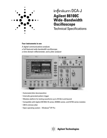
DCA-JAgilent 86100CWide-BandwidthOscilloscopeTechnical SpecificationsFour instruments in oneA digital communications analyzer,a full featured wide-bandwidth oscilloscope,a time-domain reflectometer, and a jitter analyzer Automated jitter decomposition Internally generated pattern trigger Modular platform for testing waveforms up to 40 Gb/s and beyond Compatible with Agilent 86100A/B-series, 83480A-series, and 54750-series modules 200 fs intrinsic jitter Open operating system – Windows XP Pro
Table of ContentsOverviewFeatures340 Gb/s9SpecificationsMainframe & triggering(includes precision time base module)10Computer system & storage12ModulesOverviewModule selection eDual opticalDual electricalTDRClock recoveryOrdering Information2131415171819202021
Overview of infiniium DCA-JFeaturesPatternLock TriggeringThe Enhanced Trigger Option (Option 001) on the 86100Cprovides a fundamental capability never availablebefore in an equivalent time sampling oscilloscope.This new triggering mechanism enables the DCA-J togenerate a trigger at the repetition of the input datapattern – a pattern trigger. Historically, this capabilityrequired the pattern source to provide this type oftrigger output to the scope. PatternLock automaticallydetects the pattern length, data rate and clock ratemaking the complex triggering mechanism transparentto the user.PatternLock enables the 86100C to behave more like areal-time oscilloscope in terms of user experience.Investigation of specific bits within the data pattern isgreatly simplified. Users that are familiar with real-timeoscilloscopes, but perhaps less so with equivalent timesampling scopes will be able to ramp up quickly.PatternLock adds another new dimension to patterntriggering by enabling the mainframe software to takesamples at specific locations in the data pattern withoutstanding timebase accuracy. This capability is abuilding block for many of the new capabilities availablein the 86100C described later.Four Instruments in OneThe 86100C Infiniium DCA-J can be viewed as fourhigh-powered instruments in one: A general-purpose wide-bandwidth samplingoscilloscope; the new PatternLock triggeringsignificantly enhances the usability as a generalpurpose scope A digital communications analyzer; the newEyeline Mode feature adds a powerful new tool to eyediagram analysis A time domain reflectometer A jitter analyzerJust select the instrument mode and start makingmeasurements.Configurable to meet your needsThe 86100C supports a wide range of plug-ins for testingboth optical and electrical signals. Select plug-ins to getthe specific bandwidth, filtering, and sensitivity you need.Jitter AnalysisThe “J” in DCA-J represents jitter analysis. The 86100Cis a Digital Communications Analyzer with Jitteranalysis capability. The 86100C adds a fourth modeof operation – Jitter Mode.As data rates increase in both electrical and opticalapplications, jitter is an ever increasing measurementchallenge. Decomposition of jitter into its constituentcomponents is becoming more critical. It providescritical insight for jitter budgeting and performanceoptimization in device and system designs. Manyemerging standards require jitter decomposition forcompliance. Traditionally, techniques for separation ofjitter have been complex and often difficult to configure,and availability of instruments for separation of jitterbecomes very limited as data rates increase.The DCA-J provides simple, one button setup andexecution of advanced waveform analysis. Jitter Modedecomposes jitter into its constituent components andpresents jitter data in various insightful displays. JitterMode operates at all data rates the 86100C supports,removing the traditional data rate limitations fromcomplex jitter analysis. The 86100C brings severalkey attributes to jitter analysis: Very low intrinsic jitter (both random anddeterministic) translates to a very low jitter noisefloor which provides unmatched jitter measurementsensitivity. Wide bandwidth measurement channels deliver verylow intrinsic data dependent jitter and allow analysisof jitter on all data rates up to 40 Gb/s and beyond. PatternLock triggering technology provides samplingefficiency that makes jitter measurements very fast.Jitter analysis functionality is segmented into twosoftware package options. Option 100 is the standardjitter analysis software, and Option 101 is the advancedwaveform analysis software. Option 100 includes: Decomposition of jitter into Total Jitter (TJ), RandomJitter (RJ), Deterministic Jitter (DJ), Periodic Jitter(PJ), Data Dependent Jitter (DDJ), Duty CycleDistortion (DCD), and Jitter induced by IntersymbolInterference (ISI). Various graphical and tabular displays of jitter data Export of jitter data to convenient delimited textformat Save / recall of jitter databaseWindows is a U.S. registered trademark of Microsoft Corporation.3
Option 101 requires Option 100 and adds additionalcapability: Periodic jitter frequency Isolation and analysis of Sub-Rate Jitter (SRJ),that is, periodic jitter that is at an integer sub-rateof the bitrate. Bathtub curve display Jitter Mode operation with the patented 86107APrecision Timebase Module Adjustable total jitter probabilityAs bit rates increase, channel effects cause significanteye closure. Many new devices and systems areemploying equalization and pre/de-emphasis tocompensate for channel effects. Option 101 AdvancedWaveform Analysis will provide key tools to enabledesign and test of devices and systems that must dealwith difficult channel effects: Capture of long single valued waveforms. PatternLocktriggering and the waveform append capability ofOption 101 enable very accurate pulse train data setsup to 256 megasamples long. Equalization. The DCA-J can take a long singlevalued waveform and route it through an equalizeralgorithm (default or user defined) and displaythe resultant equalized waveform. The user cansimultaneously view the input (distorted) and output(equalized) waveforms. Pattern lock triggering with 86107ADigital communications analysisAccurate eye-diagram analysis is essential forcharacterizing the quality of transmitters used from100 Mb/s to 40 Gb/s. The 86100C was designedspecifically for the complex task of analyzing digitalcommunications waveforms. Compliance mask andparametric testing no longer require a complicatedsequence of setups and configurations. If you can pressa button, you can perform a complete compliance test.The important measurements you need are right at yourfingertips, including: industry standard mask testing with built-inmargin analysis extinction ratio measurements with accuracy andrepeatability eye measurements: crossing %, eye height and width,‘1’ and ‘0’ levels, jitter, rise or fall times and moreThe key to accurate measurements of lightwavecommunications waveforms is the optical receiver.The 86100C has a broad range of precision receiversintegrated within the instrument. Built-in photodiodes, with flat frequency responses,yield the highest waveform fidelity. This provides highaccuracy for extinction ratio measurements.4 Standards-based transmitter compliance measurementsrequire filtered responses. The 86100C has a broadrange of filter combinations. Filters can be automaticallyand repeatably switched in or out of the measurementchannel remotely over GPIB or with a front panelbutton. The frequency response of the entiremeasurement path is calibrated, and will maintainits performance over long-term usage. The integrated optical receiver provides a calibratedoptical channel. With the accurate optical receiverbuilt into the module, optical signals are accuratelymeasured and displayed in optical power units.Switches or couplers are not required for an averagepower measurement. Signal routing is simplified andsignal strength is maintained.Eye diagram mask testingThe 86100C provides efficient, high-throughputwaveform compliance testing with a suite of standardsbased eye-diagram masks. The test process has beenstreamlined into a minimum number of keystrokes fortesting at industry standard data rates.Standard masksRate (Mb/s)1X Gigabit Ethernet12502X Gigabit Ethernet250010 Gigabit Ethernet9953.2810 Gigabit Ethernet10312.5Fibre Channel1062.52X Fibre Channel21254X Fibre Channel425010X Fibre /OC1929953.28STM64/OC192 FEC10664.2STM64/OC192 FEC10709STM64/OC192 Super FEC12500STM256/OC76839813STS1 EYE51.84STS3 EYE155.52Other eye-diagrammasks are easilycreated through scalingthose listed at left. Inaddition, mask editingallows for new maskseither by editingexisting masks, orcreating new masksfrom scratch. A newmask can also becreated or modified onan external PC using atext editor such asNotepad, then can betransferred to theinstrument’s harddrive using LAN orthe A: drive.Perform these maskconformance testswith convenientuser-definable measurement conditions, such as maskmargins for guardband testing, number of waveformstested, and stop/limit actions.
Eyeline ModeEyeline Mode is a new feature only available in the86100C that provides insight into the effects of specificbit transitions within a data pattern. The unique viewassists diagnosis of device or system failures do tospecific transitions or sets of transitions within apattern. When combined with mask limit tests, EyelineMode can quickly isolate the specific bit that caused amask violation.Eyeline Mode uses PatternLock triggering to build up aneye diagram from samples taken sequentially throughthe data pattern. This maintains a specific timingrelationship between samples and allows Eyeline Modeto draw the eye based on specific bit trajectories.Effects of specific bit transitions can be investigated,and averaging can be used with the eye diagram.Traditional triggering methods on an equivalent timesampling scope are quite effective at generating eyediagrams. However, these eye diagrams are made up ofsamples whose timing relationship to the data pattern iseffectively random, so a given eye will be made up ofsamples from many different bits in the pattern takenwith no specific timing order. The result is thatamplitude versus time trajectories of specific bits inthe pattern are not visible. Also, averaging of the eyediagram is not valid, as the randomly related sampleswill effectively average to zero.Measurement speedIn manufacturing, it is a battle to continually reduce thecost per test. Solution: Fast PC-based processors, resultingin high measurement throughput and reduced test time.Oscilloscope modeMeasureStandard measurements/featuresThe following measurements are available from the toolbar, as well as the pull down menus. Measurementsavailable are dependent on the DCA-J operating mode.Jitter ModeJitter Mode requires Option 001 Enhanced Trigger hardware.There are two jitter analysis software packages for theDCA-J. Option 100 is the standard jitter analysissoftware, and Option 101 is the advanced waveformanalysis software. Option 101 requires Option 100.Measurements (Option 100 Jitter Analysis)Total Jitter (TJ), Random Jitter (RJ), DeterministicJitter (DJ), Periodic Jitter (PJ), Data DependentJitter (DDJ), Duty Cycle Distortion (DCD), IntersymbolInterference (ISI)Measurement speed has been increased with both fasthardware and a user-friendly instrument. In the lab,don’t waste time trying to figure out how to make ameasurement. With the simple-to-use 86100C, you don’thave to relearn how to make a measurement each timeyou use it.TimeRise Time, Fall Time, Jitter RMS, Jitter p-p, Period,Frequency, Pulse Width, - Pulse Width, Duty Cycle,Delta Time, [Tmax, Tmin, Tedge—remote commands only]AmplitudeOvershoot, Average Power, V amptd, V p-p, V rms,V top, V base, V max, V min, V avgEye/mask modeNRZ eye measurementsExtinction Ratio, Jitter RMS, Jitter p-p, Average Power,Crossing Percentage, Rise Time, Fall Time, One Level,Zero Level, Eye Height, Eye Width, Signal to Noise(Q-Factor), Duty Cycle Distortion, Bit Rate,Eye AmplitudeRZ Eye MeasurementsExtinction Ratio, Jitter RMS, Jitter p-p, Average Power,Rise Time, Fall Time, One Level, Zero Level, Eye Height,Eye Amplitude, Opening Factor, Eye Width, PulseWidth, Signal to Noise (Q-Factor), Duty Cycle, Bit Rate,Contrast RatioData Displays (Option 100 Jitter Analysis)TJ histogram, RJ/PJ histogram, DDJ histogram,Composite histogram, DDJ versus Bit positionMask TestMeasurements (Option 101 AdvancedWaveform Analysis)Sub-Rate Jitter (SRJ)TDR/TDT Mode (requires TDR module)Open Mask, Start Mask Test, Exit Mask Test, Filter,Mask Test Margins, Mask Test Scaling, Create NRZ MaskQuick TDR, TDR/TDT Setup, Normalize, Response,Rise Time, Fall Time, TimeData Displays (Option 101 AdvancedWaveform Analysis)Bathtub curve, SRJ analysis, Equalized waveform5
Standard FunctionsStandard functions are available through pull downmenus and soft keys, and some functions are alsoaccessible through the front panel knobs.MarkersTwo vertical and two horizontal (user selectable)TDR MarkersHorizontal — seconds or meterVertical — volts, ohms or Percent ReflectionPropagation — Dielectric Constant or VelocityLimit testsAcquisition limitsLimit Test Run Until Conditions — Off, # of Waveforms,# of SamplesReport Action on Completion — Save waveform tomemory or disk, Save screen image to diskMeasurement limit testSpecify Number of Failures to Stop Limit TestWhen to Fail Selected Measurement — Inside Limits,Outside Limits, Always Fail, Never FailReport Action on Failure - Save waveform to memoryor disk, Save screen image to disk, Save summaryto diskMask limit testSpecify Number of Failed Mask Test SamplesReport Action on Failure — Save waveform to memoryor disk, Save screen image to disk, Save summaryto diskConfigure measurementsThresholds10%, 50%, 90% or 20%, 50%, 80% or CustomEye BoundariesDefine boundaries for eye measurmentsDefine boundaries for alignmentFormat Units forDuty Cycle Distortion — Time or PercentageExtinction/Contrast Ratio — Ratio, Decibelor PercentageEye Height — Amplitude or Decibel (dB)Eye Width — Time or RatioAverage Power — Watts or Decibels (dB)Top Base DefinitionAutomatic or Custom Time DefinitionFirst Edge Number, Edge Direction, ThresholdSecond Edge Number, Edge Direction, ThresholdJitter ModeUnits (time or unit interval)Signal type (data or clock)Measure based on edges (all, rising only, falling only)Graph layout ( single, split, quad)Quick Measure Configuration4 User Selectable Measurements for Each ModeDefault Settings(Eye/Mask Mode)Extinction Ratio, Jitter RMS, Average Power,Crossing PercentageDefault Settings(Oscilloscope Mode)Rise Time, Fall Time, Period,V amptdHistogramsConfigureHistogram scale (1 to 8 divisions)Histogram axis (vertical or horizontal)Histogram window (adjustable Window viamarker knobs)Math measurements4 User definable functions Operator — magnify,invert, subtract, versus, min, maxSource — channel, function, memory, constant,response (TDR)CalibrateAll calibrationsModule (amplitude)Horizontal (time base)Extinction ratioProbeOptical channelFront panel calibration output levelUser selectable –2V to 2VUtilitiesSet time and dateRemote interfaceSet GPIB interfaceTouch screen configuration/calibrationCalibrationDisable/enable touch screenUpgrade softwareUpgrade mainframeUpgrade module6
Built-in information systemClock recovery loop bandwidthThe 86100C has a contextsensitive on-line manualproviding immediate answersto your questions about usingthe instrument. Links on themeasurement screen take youdirectly to the information youneed including algorithms forall of the measurements. The on-linemanual includes technicalspecifications of the mainframe andplug-in modules. It also providesuseful information such as themainframe serial number, moduleserial numbers, firmware revisionand date, and hard disk free space.There is no need for a large papermanual consuming your shelf space.The Agilent clock recovery moduleshave two loop bandwidth settings.Loop bandwidth is very importantin determining the accuracy of yourwaveform when measuring jitter, aswell as testing for compliance. Narrow loop bandwidth providesa clean system clock for accuratejitter measurements Wide loop bandwidth in someapplications is specified in thestandards for compliance testing.It allows the recovered clock totrack the data and is useful forextracting a signal that may havepropagated through a complexnetwork and have large amounts ofjitter. While this obviously negatesany ability to quantify the jitter, itdoes allow other parameters of aneye to be measured.File sharing and storageUse the internal 40 GB hard drive tostore instrument setups, waveforms,or screen images. A 64MB USBmemory stick is included with themainframe. Combined with the USBport on the front panel this providesfor quick and easy file transfer.Images can be stored in formatseasily imported into variousprograms for documentation andfurther analysis. LAN interface isalso available for network filemanagement and printing. Anexternal USB CD-RW drive isincluded with the mainframe. Thisenables easy installation of softwareapplications as well as storage oflarge amounts of data.Powerful display modesUse gray scale and color graded tracedisplays to gain insight into devicebehavior. Waveform densities aremapped to color or easy-to-interpretgray shades. These are infinitepersistence modes where shadingdifferentiates the number of timesdata in any individual screen pixelhas been acquired.Internal triggeringthrough clock recoveryTypically an external timingreference is used to synchronize theoscilloscope to the test signal. Incases where a trigger signal is notavailable, clock recovery modules areavailable to derive a timing referencedirectly from the waveform to bemeasured. The Agilent 8349XA seriesof clock recovery modules areavailable for electrical, multimodeoptical, and single-mode opticalinput signals. All 8349XA moduleshave excellent jitter performance toensure accurate measurements. Eachclock recovery module is designed tosynchronize to a variety of commontransmission rates.Note: When using recovered clocksfor triggering, the amount of jitterobserved will depend on the loopbandwidth. As the loop bandwidthincreases, more jitter is “trackedout” by the clock recovery resultingin less observed jitter. This isdesired by many standards, butit is important in a measurementenvironment to understand theeffect that the clock recovery has onthe quantity of jitter being measured.7
Waveform autoscalingAutoscaling provides quick horizontal and vertical scalingof both pulse and eye-diagram (RZ and NRZ) waveforms.Time domain reflectometery/time domaintransmission (TDR/TDT)High-speed design starts with the physical structure.The transmission and reflection properties of electricalchannels and components must be characterized toensure sufficient signal integrity. Reflections and signaldistortions must be kept at a minimum. Use TDR andTDT to optimize microstrip lines, PC board traces, SMAedge launchers and coaxial cables.Calibration techniques, unique to the 86100C, providehighest precision by removing cabling and fixturingeffects from the measurement results. Translation ofTDR data to complete single-ended, differential, andmixed mode S-parameters are available through theN1930A Physical Layer Test System software. Highertwo-event resolution and ultra high-speed impedancemeasurements are facilitated through TDR pulseenhancers from Picosecond Pulse Labs1.Gated triggeringTrigger gating port allows easy external control of dataacquisition for circulating loop or burst-dataexperiments. Use TTL-compatible signals to controlwhen the instrument does and does not acquire data.Easier calibrationsCalibrating your instrument has been simplified byplacing all the performance level indicators andcalibration procedures in a single high-level location.This provides greater confidence in the measurementsmade and saves time in maintaining equipment.1 Picosecond Pulse Labs (www.picosecond.com)8Stimulus response testingUsing the Agilent N490XA Serial BERTError performance analysis represents an essential partof digital transmission test. The Agilent 86100C andN490XA Serial BERT have similar user interfaces andtogether create a powerful test solution.Transitioning from the Agilent 83480A and86100A/B to the 86100CWhile the 86100C has powerful new functionality thatits predecessors don’t have, it has been designed tomaintain compatibility with the Agilent 86100A, 86100Band Agilent 83480A digital communications analyzersand Agilent 54750A wide-bandwidth oscilloscope. Allmodules used in the Agilent 86100A/B, 83480A and54750A can also be used in the 86100C. The remoteprogramming command set for the 86100C has beendesigned so that code written for the 86100A or 86100Bwill work directly. Some code modifications are requiredwhen transitioning from the 83480A and 54750A, butthe command set is designed to minimize the level ofeffort required.
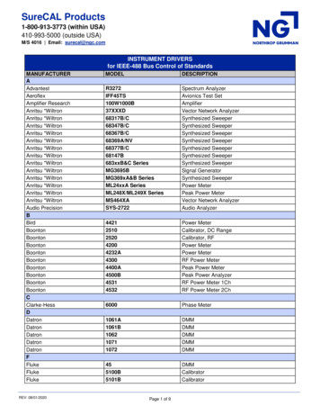
Lowest intrinsic jitterThe patented 86107A precisiontimebase reference module representsone of the most significantimprovements in wide-bandwidthsampling oscilloscopes in over adecade. Jitter performance hasbeen reduced by almost an orderof magnitude to 200 fs RMS.Oscilloscope jitter is virtuallyeliminated! The reduced jitter of the86107A precision timebase moduleallows you to measure the true jitterof your signal. When using the86107A, the minimum timebaseresolution for oscilloscope andeye/mask displays is 500 fs/division,rather than 2 ps/div with thestandard timebase.The standard timebase of the86100C has very low intrinsicjitter compared to other advancedwaveform analysis solutions.However, for users who need theabsolute best sensitivity for theirjitter measurements, the 86107Aprovides the ultimate timebaseperformance. Using the 86107Awith Jitter Mode requires theOption 101 Advanced WaveformAnalysis software package. Jittermeasurements with the 86107A aretargeted at users who are trying toaccurately measure very low levelsof jitter and need to minimize thejitter contribution of the scope.The 86107A requires an electricalreference clock that is synchronouswith the signal under test. Forspecific requirements of the clocksignal, see the 86107A specificationson page 11.Accurate views of your40 Gb/s waveformsWhen developing 40 Gb/s devices,even a small amount of inherentscope jitter can become significantsince 40 Gb/s waveforms only havea bit period of 25 ps. Scope jitterof 1ps RMS can result in 6 to 9 psof peak-to-peak jitter, causingeye closure even if your signal isjitter-free. The Agilent 86107Areduces the intrinsic jitter of 86100family mainframes to the levelsnecessary to make quality waveformmeasurements on 40 Gb/s signals.The same 40 GHz sinewavecaptured using current DCA (top)and now with 86107A precisiontimebase module (bottom).Meeting your growing needfor more bandwidthToday’s communication signals havesignificant frequency content wellbeyond an oscilloscope’s 3-dBbandwidth. A high-bandwidth scopedoes not alone guarantee an accuraterepresentation of your waveform.Careful design of the scope’sfrequency response (both amplitudeand phase) minimizes distortionsuch as overshoot and ringing.The Agilent 86116A, 86116B and86109B are plug-in modules thatinclude an integrated opticalreceiver designed to provide theoptimum in bandwidth, sensitivity,and waveform fidelity. The 86116Bextends the bandwidth of the86100C infiniium DCA-J to 80 GHzelectrical, 65 GHz optical in the1550 nm wavelength band. The86116A covers the 1300 nm and1550 nm wavelength bands with63 GHz of electrical bandwidth and53 GHz of optical bandwidth. The86109B is an economical solutionwith 50 GHz electrical and 40 GHzoptical bandwidth. You can buildthe premier solution for 40 Gb/swaveform analysis around the 86100mainframe that you already own.Performing return-to-zero(RZ) waveform measurementsAn extensive set of automaticRZ measurements are built-in forthe complete characterization ofreturn-to-zero (RZ) signals at thepush of a button.9
SpecificationsSpecifications describe warranted performance over the temperature range of 10 C to 40 C (unless otherwise noted). The specifications areapplicable for the temperature after the instrument is turned on for one (1) hour, and while self-calibration is valid. Many performance parameters areenhanced through frequent, simple user calibrations. Characteristics provide useful, non-warranted information about the functions andperformance of the instrument. Characteristics are printed in italic typeface.Factory Calibration Cycle -For optimum performance, the instrument should have a complete verification of specifications once every twelve (12) months.General specificationsThis instrument meets Agilent Technologies’ environmental specifications (section 750) for class B-1 products with exception as described for temperature andcondensation. Contact your local field engineer for complete details. Product specifications and descriptions in this document subject to change without VibrationOperatingNon-operatingPower requirementsVoltagePower (including modules)WeightMainframe without modulesTypical moduleMainframe dimensions (excluding handle)Without front connectors and rear feetWith front connectors and rear feet10 C to 40 C (50 F to 104 F)–40 C to 65 C (–40 F to 158 F)Up to 90% humidity (non-condensing) at 40 C ( 104 F)Up to 95% relative humidity at 65 C ( 149 F)Up to 4,600 meters (15,000 ft)Up to 15,300 meters (50,000 ft)Random vibration 5 to 500 Hz, 10 minutes per axis, 0.21 g (rms)Random vibration 5 to 500 Hz, 10 minutes per axis, 0.3 g (rms); Resonant search, 5 to 500 Hzswept sine, 1 octave/min sweep rate, 0.5 g, 5 minute resonant dwell at 4 resonances/axis90 to 132 or 198 to 264 Vac, 48 to 66 Hz604 VA; 391 W15.5 kg (34 lb)1.2 kg (2.6 lb)215.1 mm H x 425.5 mm W x 566 mm D (8.47 in x 16.75 in x 22.2 in)215.1 mm H x 425.5 mm W x 629 mm D (8.47 in x 16.75 in x 24.8 in)Mainframe specificationsHORIZONTAL SYSTEM (time base)Scale factor (full scale is ten divisions)MinimumMaximumDelay1MinimumMaximumTime interval accuracy 2Time interval accuracy – jitter mode operation 4Time interval accuracy – with 86107Aprecision timebaseTime interval resolutionDisplay unitsVERTICAL SYSTEM (channels)Number of channelsVertical resolutionFull resolution channel scalesAdjustmentsRecord lengthPATTERN LOCK2 ps/div (with 86107A: 500 fs/div)1 s/div24 ns1000 screen diameters or 10 s,whichever is smaller1 ps 1.0% of time reading 38 ps 0.1% of time reading1 ps 200 fs40.1 ns1000 screen diameters or 25.401 µs,whichever is smaller (screen diameter)/(record length) or 62.5 fs,whichever is largerBits or time (TDR mode–meters)4 (simultaneous acquisition)14 bit A/D converter (up to 15 bits with averaging)Adjusts in a 1-2-5-10 sequence for coarse adjustment or fine adjustment resolutionfrom the front panel knobScale, offset, activate filter, sampler bandwidth, attenuation factor, transducer conversion factors16 to 4096 samples – increments of 11 Time offset relative to the front panel trigger input on the instrument mainframe.2 Dual marker measurement performed at a temperature within 5 C of horizontal calibration temperature.3 Delay settings: time is in the range (26 N*4 ns) 1.9 ns, where N 0, 1, 2, . 17.4 Characteristic performance. Test configuration: PRBS of length 27 – 1 bits, Data and Clock 10 Gb/s.10250 ns/div
Mainframe specifications (continued)Standard (direct trigger)Trigger ModesInternal trigger1External direct trigger2Limited bandwidth3Full bandwidthExternal Divided er sensitivityOption 001 (enhanced trigger)FreerunDC to 100 MHzDC to 3.2 GHzN/AN/ATrigger configurationTrigger level adjustmentEdge selectHysteresis5Trigger gatingGating input levels(TTL compatible)3 GHz to 13 GHz (3 GHz to 15 GHz)50 MHz to 13 GHz (50 MHz to 15 GHz) 1.0 ps RMS 5*10E-5 of delay setting41.5 ps RMS 5*10E-5 of delay setting4200 m Vpp (sinusoidal input or200 ps minimum pulse width)1.2 ps RMS for time delays less than 100 ns61.7 ps RMS for time delays less than 100 ns6200 m Vpp sinusoidal input: 50 MHz to 8 GHz400 m Vpp sinusoidal input: 8 GHz to 13 GHz600 m Vpp sinusoidal input: 13 GHz to 15 GHz–1 V to 1 VPositive or negativeNormal or high sensitivityAC coupledN/AN/ADisable: 0 to 0.6 VEnable: 3.5 to 5 VPulse width 500 ns, period 1 µsDisable: 27 ns trigger period Max time displayedEnable: 100 nsGating delayTrigger impedanceNominal impedanceReflectionConnector typeMaximum trigger signal50 Ω10% for 100 ps rise time3.5 mm (male)2 V peak-to-peak1 The freerun trigger mode internally generates an asynchronous trigger that allows viewing the sampled signal amplitude without an external trigger signal but provides no timing information. Freerun is useful introubleshooting external trigger problems.2 The sampled input signal timing is recreated by using an externally supplied trigger signal that is synchronous with the sampled signal input.3 The DC to 100 MHz mode is used to minimize the effect of high frequency signals or noise on a low frequency trigger signal.4 Measured at 2.5 GHz with the triggering level adjusted for optimum trigger.5 High Sensitivity Hysteresis Mode improves the high frequency trigger sensitivity but is not recommended when using noisy, low frequency signals that may result in false triggers without normal hysteresis enabled.6 Slew rate 2V/nsPrecision time base 86107A186107A Option 01086107A Option 02086107A Option 040Trigger bandwidth2.4 to 4.0 GHz9.0 to 12.6 GHz9.0 to 12.6 GHz18.0 to 25.0 GHzTypical jitter (RMS)2.4 to 4.0 GHz trigger: 280 fs 200 fs9.0 to 12.6 GHz18.0 to 25.0 GHz39.0 to 43.0 GHz9 to 12.6 GHz, 18 to 25 GHztrigger bands: 250 fs38 to 45 GHz trigger: 200 fsTime base linearity errorI
The 86100C supports a wide range of plug-ins for testing both optical and electrical signals. Select plug-ins to get the specific bandwidth, filtering, and sensitivity you need. Jitter Analysis The "J" in DCA-J represents jitter analysis. The 86100C is a Digital Communications Analyzer with Jitter analysis capability. The 86100C adds a .