Transcription
HANDS-ONPRINT READINGFOR WELDERSPYWORKBOOKREVIEWCOBased on AWS A2.4:2012Michael Mohn, CWITechnology Education Resources, LLCMonroe, Michigan
HANDS-ONPRINT READINGFOR WELDERSWORKBOOKIEWCOPYBased on AWS A2.4:2012EVTechnology Education Resources, LLCRCopyright 2008, 2009, 2012by M. MohnAll rights reserved. No part of this book maybe reproduced, in any form or by any means,without written permission from the publisher.Printed in the United States of America10 9 8 7 6ISBN 0-9624986-2-9
CONTENTSINTRODUCTIONTOOLS AND SUPPLIESSECTION I – WELDING SYMBOLSPY1. Introduction to Welding Symbols .12. Fillet Welds .73. Joint Types and Square-Groove, V-Groove, and BevelGroove Welds .154. Additional Groove Weld Types: U-Groove, J-Groove, and FlaredGroove; Groove Weld Lengths and Arrangement .275. Additional Details: Combination Welds, Multiple ReferenceLines, and Tail Notes .396. Additional Details: Field Weld, Weld Contour, and CompleteJoint Penetration (Melt-Through) .477. Groove Weld Details: Back and Backing Welds, and Backgouging.518. Groove Weld Details: Backing, Spacers, and Consumable Inserts.559. Plug and Slot Welds.5910. Spot, Projection, and Seam Welds .6911. Edge Welds, Stud Welds, and Surfacing Welds.7712. Brazing Symbols and Nondestructive Examination Symbols .87OSECTION 2 – WELDING SYMBOLS WORKSHEETS (tear-out pages)EVIEWCChapter 1 Worksheet .95Chapter 2 Worksheet .99Chapter 3 Worksheet .103Chapter 4 Worksheet .109Chapter 5 Worksheet .117Chapter 6 Worksheet .123Chapter 7 Worksheet .129Chapter 8 Worksheet .133Chapter 9 Worksheet .137Chapter 10 Worksheet.143Chapter 11 Worksheet.147Chapter 12 Worksheet.153SECTION 3 – PRINT READING LAB WORK (tear-out pages)RMeasuring Units and Tools Worksheet.157Converting Measuring Units Worksheet .163Project 1—Intermittent Fillet Welds .169Project 2—Step Fixture Block.171Project 3—Keyed Angle Mount.173Project 4—Box Section .175Example 1—Storage Tank Platform .177Example 2—Stock Pusher Guide .179Project 5—Post Base Assembly .181Project 6—Pulley Mount Bracket Assembly .183Project 7—Watertight Door Hinge Assembly.185Projects 8, 9, and 10—Test Weldments .187
SECTION 4, PRINTSREVIEWCOPYFoam Panel—Cutting Sketch, 1 sheetProject 1—Intermittent Fillet Welds, 2 sheetsProject 2—Step Fixture Block, 1 sheetProject 3—Keyed Angle Mount, 1 sheetProject 4—Box Section, 1 sheetExample 1—Storage Tank Platform, 6 sheetsExample 2—Stock Pusher Guide, 5 sheetsProject 5—Post Base Assembly, 1 sheetProject 6—Pulley Mount Bracket Assembly, 2 sheetsProject 7—Watertight-Door Hinge Assembly, 2 sheetsProject 8—Test Weldment 1, 1 sheetProject 9—Test Weldment 2M, 1 sheetProject 10—Test Weldment 3, 1 sheet
INTRODUCTIONWelding symbols and print reading are indispensable skills for the modern welder. Thishands-on course was developed and fine-tuned over a ten-year period at Monroe CountyCommunity College (MI) for the Welding Technology program.REVIEWCOPYThe hands-on nature of this course makes it unique among typical print reading courses.In most textbook-based courses, students simply look at numerous sample prints andanswer various questions in hope that they will learn to read prints. In this course,however, building weldment models according to prints leaves no doubt as to printreading ability. Using foam instead of steel, and glue instead of filler metal, allows thestudent to make both simple and advanced weldments while concentrating on buildingprint reading skills. The course finishes with three weldment samples which match theAWS Certified Entry-Level Welder test weldments. Those welding students who are partof the AWS SENSE program will find this aspect Hands-On Print Reading for Weldersespecially valuable.
WIEEVROCPY
TOOLS AND SUPPLIESFor this hands-on course, you will be constructing ten weldment projects from expandedpolystyrene foam board, PVC pipe, and hot-melt glue. In addition to the prints in thisworkbook, the following supplies and tools will be used for constructing the models inthis course:Expendable Supplies 11″ x 17″ x 3/16″ (5mm) expanded polystyrene foam, 4 sheets. Refer to the cuttingsheet to ensure that you will be able to obtain all the needed pieces from the 4sheets. There will be a little left over for rework if needed.11″ x 17″ x 5/8″ (16mm) expanded polystyrene foam, 1 sheet. For two of theprojects, you will be gluing three layers of 5/8″ foam together with PVA (whiteglue) to make a thicker block.¾″ Schedule 40 PVC pipe, 7 pieces of assorted lengths.PVA (white glue).Low temperature glue sticks. Don’t use high temperature glue sticks onpolystyrene foam—it will melt the foam.PY ToolsCOWIE EV Safety Glasses. Always wear safety glasses when working with tools.Basic drafting kit, including compass and protractor.Square.Inch/metric tape measure.Cutting board. Always use the cutting board when cutting foam with a razorknife. Don’t use this board for food, especially after using it in the shop.Razor knife.Hole saw. You can use the hole saw by hand to cut foam, or chuck it into a drillpress (not included).Fine tooth saw. Good for cutting thick foam pieces.Low temperature glue gun. Use with the low-temperature glue sticks for“welding” the models together.R
WIEEVROCPY
1. Introduction to Welding SymbolsPurpose of Welding SymbolsWelding symbols are used on engineering drawings to convey welding, brazing, and/ornondestructive examination requirements. They can be simple, showing only the weldlocations, or complex, showing all aspects of a weld including joint design, type of weld,extent of welding, finishing method, and even the welding process to be used. Thewelding symbols presented in this text are based on the most current edition of AWSA2.4, Standard Symbols for Welding, Brazing, and Nondestructive Examination,published by the American Welding Society. These are the symbols used on drawingsthroughout the United States of America. Welding symbols used in Europe and Asia aresimilar, with the major difference being in the appearance of the reference line and theuse of only metric measurements.The forward to AWS A2.4:2007 states the need for welding symbols quite clearly:COPYJoining processes and examination methods cannot take their proper placeas fabricating tools unless means are provided for conveying informationfrom the designer to joining and inspection personnel. The symbols in thispublication are intended to be used to facilitate communication among thedesigner, fabrication, and inspection personnel. Statements such as “to bewelded throughout” or “to be completely welded,” in effect, transfer thedesign responsibility from the designer to production personnel, whocannot be expected to know design requirements.EVIEWWhat remains unfortunate in the welding industry is that while many welders studywelding symbols extensively, many engineers and designers do not; and therefore it maybe up to the welder to interpret the designer’s intent from often incorrectly drawn weldingsymbols. A thorough understanding of proper welding symbols by both welder anddesigner is essential to transmit the design intent to the finished product.Reference Line and ArrowRAll welding symbols are based on a horizontal reference line. On a print, the referenceline is approximately 1-inch long, and is always horizontal. An arrow is drawn from oneend of the reference line to the weld joint on the drawing. There may not be arrowscoming off both ends of the reference line; the end of the reference line opposite thearrow is reserved for a tail bracket (more on this in a later chapter). The informationabout the weld, which is placed on the reference line, is always presented in the sameorder regardless of which end of the reference line the arrow is attached.Each weld joint on a drawing will have one, and only one, welding symbol. The weldingsymbol is usually shown in the drawing view that most clearly shows the weld location.1
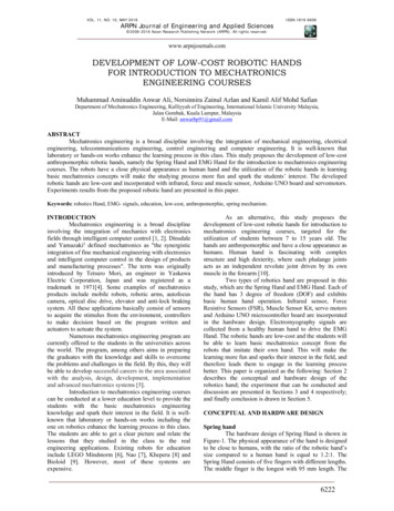
The same weld symbol is never shown in two different drawing views, just as dimensionson a drawing are never shown in two different views. As shown in the followingillustration, a weld joint has two sides: the “arrow side” (the side which the arrow ispointing at) and the “other side” (which is found by following the joint root to the sideopposite the arrow. Welding information about the “arrow side” of the joint is placedbelow the reference line, while information about the “other side” of the joint is placeabove the reference line.PYBUTT JOINTWCOCORNER JOINTEVIET-JOINTRLAP JOINTEDGE JOINT2
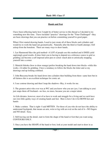
Weld Symbols*REVIEWCOPYThe most basic element of a welding symbol is the “weld symbol” itself, which tells whattype of weld is required: fillet weld, groove weld, plug weld, etc. For groove welds, thetype of joint preparation is specified by the weld symbol. There are 17 different weldsymbols, shown in the following illustration. Through the course, we will learn them all;but for now, concentrate only on the fillet weld symbol, which looks like the crosssection of a fillet weld.*Note that the terms “welding symbol” and “weld symbol” are different. The welding symbol isthe reference line, arrow, and all the stuff associated with it, while the weld symbol is just the tinypicture of the type of weld placed on the reference line.3
The weld symbol is placed below the reference line if the weld is to be located on thearrow side and above the reference line if the weld is to be located on the other side of thejoint. If both sides of the joint are to be welded, then two weld symbols are used, oneabove and one below the reference line. The fillet weld symbol is always drawn with theleft side vertical, regardless of the joint configuration or the side of the reference line withthe arrow.PRINTWELD EXAMPLECOMMENTST-joint with fillet weldon arrow side.PYT-joint with fillet weldon other side.OT-joint with fillet weldson both sides.Corner joint with filletweld on arrow side.REVIEWCHere are several examples welding symbols for fillet welds, showing arrow side andother side placement, in both plate and pipe.Corner joint with filletweld on other side.4
PRINTWELD EXAMPLECOMMENTSLap joint with fillet weldon other side.Lap joint with fillet weldon both sides.REVIEWCOPYLap joint (structuralangle to plate) withdouble-fillet welds.Fillet weld on arrowside, pipe to plate.5
PRINTWELD EXAMPLECOMMENTSFillet weld on arrowside, pipe to plate.EVIEWCOPYNote: this assembly hastwo pipes. Anotherwelding symbol would beneeded to weld the rightside pipe. The “otherside” of the specified jointwould be inside the pipeand usually cannot bewelded unless the pipe isvery short.RWelding Symbols Activities: Chapter 1 Worksheet (page 95).Print Reading Lab Work: Measuring Units and Tools Worksheet (page 157). Converting Measuring Units Worksheet (page 163).6Fillet weld on otherside, pipe to plate.Note: this assembly hasone pipe which passesthrough a hole in theplate. Unlike theexample above, the otherside can be welded.
2. Fillet WeldsThe fillet weld is the most common type of weld; for this reason we will study the filletweld symbol and its application first. Many elements of the fillet welding symbol withcarry over to the other welding symbols as well.Weld SizePYThe size of the fillet weld is placed to the left of the fillet weld symbol. Weld sizes arespecifie
REVIEW COPY HANDS-ON PRINT READING FOR WELDERS WORKBOOK Based on AWS A2.4:2012 Michael Mohn, CWI Technology Education Resources, LLC Monroe, Michigan