Transcription
RESISTANCE SYSTEMPRS-801User Manual
Table of ContentsPROSTAT PRS-801 RESITANCE SYSTEMSectionTopicPageI.Introduction & Description4II.Cautions & Warnings7III.Controls, Connections & Indicators9IV.Battery Installation and Replacement15V.Setup & Calibration16VI.Instrument Operation18VII.Instrument Maintenance36VIII.Warranty Information36General Specifications38Instrument Controls39Copyright 2012 by Prostat Corporation. All rights reserved. Printed in the United States of America. No part of thismanual may be used or reproduced in any manner whatsoever without written permission. For information contactProstat Corporation, 1072 Tower Lane, Bensenville, IL 60106 USAProstat is the registered trademark of Prostat Corporation
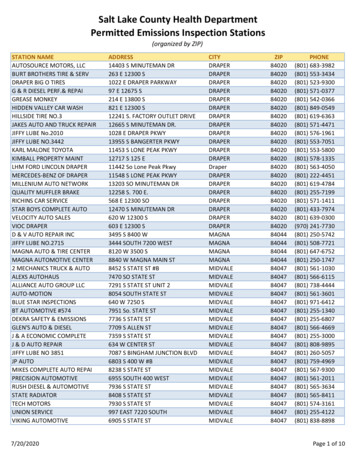
PRS-801 Resistance SystemI. Introduction & DescriptionThe PRS-801 Resistance System is capable of precision resistance measurements from 0.1 up to 2.0x10¹⁴ ohms with an overall measurement tolerance of 5%. Its wide range and close tolerance make it the ideal instrument for measuring resistance to a variety of ESD and general industry specifications. It isoperated by microprocessors that control the instrument’s measurementprocess, resistance auto ranging, test voltage selection, electrification periods,and display functions. It can be operated in either fully automatic or manualmodes, or a combination of automatic and manual modes.The PRS-801 is unique in that it stores up to 80 resistance measurements in itsnon-volatile memory. Its software transfers stored data to Excel spreadsheets.Figure 1: PRS-801 duringpower upIts accuracy is based on its ability to make and process several thousand measurements per second, averaging them until a stable set of eight consecutivemeasurements, all within 5% of each other are obtained. Typically, measurements at less than 1 ohm are within 5% of tolerance, and those between 1.0and 1.0x10¹² ohms are within 0.5% of laboratory references. Measurementsfrom 1.0x10¹² to less than 2.0x10¹⁴ ohms are within 5% tolerance using shieldedcables, to a maximum of ¼ decade deviation from a laboratory reference ( 40%tolerance) depending on cables and procedures employed by the operator.While quite sophisticated in design, the PRS-801 Resistance System is easy to use and extremely helpful inmaking accurate ESD auditing measurements, or general resistance and continuity checks.CAUTIONTo avoid electrical shock or damage to the PRS-801 Resistance System, readthis manual completely before installing batteries or using the instrument.A. Measurement ApplicationsThe PRS-801 Resistance System is designed to measure resistance characteristics of electrostaticdischarge (ESD) control materials and products to current ESD industry standards, including:Wrist Straps (ANSI/ESD S1.1)Flooring (ANSI/ESD STM7.1)ESD CP Grounds (ANSI/ESD S6.1)Footwear (ANSI/ESD STM9.1)Equipment (ESD SP10.1)Material Handling ContainersGarments (ESD STM2.1)Worksurfaces (ANSI/ESD S4.1)Carts & Seating (ANSI/ESD STM 12.1)WorkstationsProduction Aids & Hand ToolsPackaging (ANSI/ESD STM11.11, ANSI/ESDSTM11.12 & ASTM 257), and Other ANSI/S20.20 ESD Program Control ElementsNote: Additional fixtures and electrodes supplied separately are required for many of these measurement.B. PRS-801 Resistance System Components:4Rev. D / January 2012
PRS-801 Resistance SystemThe PRS-801 Resistance System includes the following items:1. PRS-801 Resistance System Instrument with 2 each 9V alkaline batteries.IMPORTANT NOTEOnly use alkaline batteries for optimal performance.2. Two 10-foot leads (PRS-800LB & PRS-800LR) for general audit measurements up to 1.0x10¹²ohms.3. One set (PRS-801SSL & PRS-801TVL) high resistance measurement leads, including: oneshielded 42 inch sensing lead; and, one 42-inch power lead for precision measurements above1.0x1012 ohms.4. Prostat Utility Software (PRS-801CSW) enabling data transmission from the PRS-801 to Windows Excel spread sheets.5. One RS-232 output cable (PRS-801CIC) for connection to a nine-pin computer COM port.6. One heavy duty, black “Bulldog” clip (PRS-801BC)7. Two Metal Alligator Clips (PSI-870MAC)8. One Audit Test Bed (PTB-915)9. One calibration shunt for low range adjustment (PRS-801CC)Optional accessories are available for the PRS-801 Resistance System. Visit www.prostatcorp.comfor additional information.C. PRS-801 Basic Description & FunctionsThe PRS-801 Resistance System has several test, display and data logging functions:1. The PRS-801 six basic measurement modes are described in the following tableRev. D / January 20125
PRS-801 Resistance VOLTSTESTFUNCTIONSAUTOMATIC 1[Default]1.0EXXIND Ω - TΩAUTOAUTO.AUTO.AUTOMATIC 2OHMSΩ - TΩAUTOAUTO.AUTO.MANUAL 1SELECT DECADE1.0EXXIND Ω - TΩMANUALMANMAN. orAUTOMANUAL 2SELECT DECADEOHMSΩ - TΩMANUALMANMAN. orAUTOMANUAL/AUTOMATIC 1MAY SELECTSTARTING DECADE1.0EXXIND Ω - TΩAUTO &MANUALMAN. StartAUTORunAUTO.MANUAL/AUTOMATIC 2MAY SELECTSTARTING DECADEOHMSΩ - TΩAUTO &MANUALMAN. StartAUTORunMANUAL SETUP STARTINGDECADE, AUTO ADJUST RANGE,TEST VOLTS, ELECTRIFICATIONDISPLAY HOLDAUTO.SEE TABLE NOTE #3AUTOMATIC RESISTANCE RANGE,TEST VOLTS, ELECTRIFICATION,DISPLAY HOLDSEE TABLE NOTE #1TEST ONLY; NO DISPLAY HOLDUL UNDER DECADE LEVELOL OVER DECADE LEVELSEE TABLE NOTE #2TABLE NOTES:#1 AUTOMATIC:RESISTANCE RANGES IN AUTO 0.1Ω TO 2.0E 14Ω as follows@ 10V:0.1 TO 1.0E 04Ω (0.1Ω - 10KΩ)@ 10V:1.0E 04 TO 1.0E 06Ω (10KΩ - 1MΩ)@100V:1.0E 06 TO 2.0E 14Ω (1MΩ - 200TΩ)#2 MANUAL:RESISTANCE RANGES IN MAN 0.1Ω TO 2.0E 14Ω as follows@ 10V:0.1 TO 1.0E 05Ω (0.1Ω - 100KΩ)@ 10V:1.0E 03 TO 1.0E 09Ω (1KΩ- 1GΩ)@100V:2.0E 05 TO 2.0E 14Ω (200KΩ- 200TΩ)#3 AUTO-MANUAL:(Same as AUTOMATIC)RESISTANCE RANGES IN AUTO-MANUAL 0.1Ω TO 2.0E 14Ω as follows@ 10V:0.1 TO 1.0E 04Ω (0.1Ω - 10KΩ)@ 10V:1.0E 04 TO 1.0E 06Ω (10KΩ - 1MΩ)@100V:1.0E 06 TO 2.0E 14Ω (1MΩ - 200TΩ)2. The PRS-801 provides three separate test voltages for resistance measurements as indicated inthe table, above: 10 Volts10 Volts100 VoltsIn AUTOMATIC and AUTOMATIC/MANUAL modes the instrument automatically controls voltage and resistance range based on resistance characteristics of materials being measured. Inthe MANUAL mode the operator may select test voltage and and resistance range. Note thatthe most efficient mode of operation in AUTOMATIC/MANUAL for maximum battery life.6Rev. D / January 2012
PRS-801 Resistance System3. The PRS-801 displays resistance Measurements in several ways:a. 14 individual operator programmable LED’s each representing one order of magnitudefrom 103 to 1014 ohms. The operator may select from three colors, or OFF for each LED,including:GREENREDYELLOW/ORANGEOFF (Blank)b. The large Liquid Crystal Display (LCD) includes an analog (1 - 10) scale and X1, X10 and X100multiplier indication for measurement in Ω, KΩ, MΩ, GΩ and TΩ.c. Digital measurements are provided using integers and Ω, KΩ, MΩ, GΩ, TΩ indicators, or inexponential format (1.0EXX) with Ω -TΩ indicators.4. The PRS-801 includes data logging (storage) capabilities for up to 80 data points when RECORDis selected. The instrument will provide access to the memory register, calculate and displayMinimum, Maximum and Average of all measurements in the instrument’s memory wheneverRECALL is selected.Using the Prostat Utility Software, the PRS-801 can transfer all data points stored in its non-volatilememory to a Windows Excel computer spreadsheet via its RS-232 port for detailed analysis and recordmaintenance. (Windows 95, 98, 2000, ME, XP, Vista, 7, 8 and NT based computer system using an OfficeSuite 95, 97, 2000, 2007, 2010 and 2013 Excel spreadsheet program)II. Cautions & WarningsAs with any electrical device, use proper safety precautions and safe measurement procedures toavoid personnel shock and arc discharge.A. The PRS-801 Resistance System is battery operated and delivers test voltages up to 100 volts.IMPORTANT: Only use alkaline batteries in the PRS-801.B. The instrument is current limited for safety, however, if improperly used it may be capable of delivering an annoying shock to a person touching conductors energized by the PRS-801, particularly at100 volts.C. While current limited, a hazard exists in personnel reaction to a potential shock.D. To avoid personnel shock, follow the General Operations instructions at all times. Do not touchenergized electrodes or fixtures when power is applied except as specifically described in this andaccessory instructions.E. Do not operate or store the instrument in damp environments or wet conditions.Rev. D / January 20127
PRS-801 Resistance SystemCAUTIONStorage or use of this instrument in high humidity, damp or wet conditionsmay cause damage to the instrument’s electronic circuits, effect performanceand can increase the possibility of personnel shock or arc discharge.F. Do not use the PRS-801 in combustible or explosive environmentsWARNINGImproper handling and use of energized circuits may cause arc discharge,which in turn may cause the ignition of combustible materials or fumes.Do not use exposed energized circuits in flammable areas.G. Do not attempt to measure energized circuits with the PRS-801H. Do not use the PRS-801 if it becomes damaged in any wayI. Only Prostat trained instrument personnel should attempt to service or repair the PRS-801J. Other Safety & Operating Considerations1. This manual displays cautions and warnings alerting the user to hazardous operation and servicing conditions. CAUTION or WARNING headings throughout this publication flag this information, where appropriate. Follow all caution and warning instructions at all times.2. The PRS-801 is a precision instrument and should be operated by experienced personnel familiar with the use and handling of devices containing power supplies.CAUTIONThe PRS-801 Contains Electrostatic Discharge Sensitive (ESDS) componentsand includes precision alignment of circuit elements. Only Prostat trained andESD Qualified instrument repair personnel should perform service.3. The PRS-801 contains Electrostatic Discharge Sensitive (ESDS) components. Qualified personnelshould service it only at ESD Controlled workstations. Do not attempt to dismantle the PRS-801without Prostat’s authorization and expert supervision. The instrument contains exceptionally8Rev. D / January 2012
PRS-801 Resistance Systemclean circuits that are aligned and adjusted in a precise manner for optimal operation and accurate performance. Unauthorized opening of the PRS-801 housing will void the instrument’swarranty.WARNINGUnauthorized opening of the PRS-801 case or dismantling in any mannerWILL VOID THE INSTRUMENT’S WARRANTY.4. Read this manual in its entirety before installing batteries or using the PRS-801.5. Do not drop or cause unnecessary mechanical shock to your PRS-801 instrument.6. Store the instrument in a clean, dry environment. Do not expose the instrument to wet, extremely hot or cold conditions.7. If the unit is stored in a cold environment, allow it to stabilize at room temperature beforepowering up the unit. This will prevent damage due to condensation that may accumulate onthe instrument’s circuit boards.III. Controls, Connections & IndicatorsBefore operating the PRS-801 instrument become familiar with each control and display function. Athorough understanding of the instrument’s operation will make its use a pleasant experience, enhance measurement accuracy, avoid mistakes and prolong the life of the instrument.PRS-801 CONTROLS:[1] FUNCTION/ MODEToggles Through Six Operation Modes(1) AUTO: (AUTOMATIC) displays data in exponential format 1.0EXXNOTE: AUTO in exponential format, e.g., 1.3E05, is the Default start upmode when the instrument is turned ON.Rev. D / January 2012(2) AUTO: (AUTOMATIC) displays data in Ω, KΩ, MΩ, GΩ and TΩ. The instrument controls resistance ranges, test voltage and electrification periods inAUTOMATIC mode.9
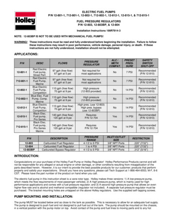
PRS-801 Resistance SystemFigure 2: PRS-801 Controls & Display Indicators(3) MANUAL: displays data in exponential format 1.0EXX(4) MANUAL: displays data in Ω, KΩ, MΩ, GΩ and TΩ(5) AUTO-MANUAL: displays data in exponential format 1.0EXX(6) AUTO-MANUAL: displays data in Ω, KΩ, MΩ, GΩ and TΩIn MANUAL, the operator selects resistance range in single decadeincrements. Test voltage may be selected by the operator, or allowedto function automatically based on resistance range selected. Theoperator determines electrification period in seconds (SEC) using thedisplayed timer in the center of the LCD.In AUTO-MANUAL the operator may select the initial resistance range indecade increments. Once set, the PRS-801 starts the measurement processfrom the preset resistance decade, rather than re-zeroing itself for eachmeasurement. This feature saves measurement cycle time and extendsbattery life. In this mode the instrument automatically controls test voltage,range and measurement electrification period.10Rev. D / January 2012
PRS-801 Resistance System[2] RESISTANCE RANGESELECTIONTwo Triangular Arrows Buttons, UP ( ) and DOWN ( ), select ResistanceMeasurement Range in single orders of magnitude while in MANUAL orAUTOMATIC/MANUAL modes[3] TEST VOLTSManual Selection of 10, 10 or 100 volts in MANUAL selects initial testvoltage. MANUAL Test Voltage & Resistance Limits are as follows:@ 10V:@ 10V:1.0E 03 to 1.0E 09Ω (1KΩ - 1GΩ)@100V:2.0E 05 to 2.0E 14Ω (200KΩ - 200TΩ)0.1 to 1.0E 05Ω (0.1Ω - 100KΩ)NOTE: Optimal minium measurement in MANUAL using 100 volts is2.0E 05.[4] RECORD/RECALLIf REC is not displayed in the lower left corner of the LCD, pressing RECORD/RECALL once turns Memory Register ON [REC will then be displayed inLCD]. If REC is ON and measurement data is stored in memory, pressingRECORD/RECALL once will provide access to the memory register. PressingRECORD/RECALL successively will calculate and sequentially displayMinimum [MIN], Maximum [MAX] and Average [AVG] of data stored in theMemory Register. If memory is ON and register contains stored data pressingRECALL will provide the following information:First Press RECALL:NOTE: MEM XX Flashes in LCD indicating number of data points in theregister and the last measurement is displayed. Pressing DOWN ( ) and UP( ) displays other data points and their respective position in the register isshown in the MEM XX section of the LCD.Second Press RECALL:Provides access to data in MemoryDisplays MIN Data Point in MemoryThird Press RECALL:Displays MAX Data Point in MemoryNOTE: When displayed, OL [Over Level] indicates a measurement greaterFourth Press RECALL:NOTE:Displays AVG of all Memory Data PointsOL [Over Level] measurements [ 2.0x10¹⁴ ohms] are not included indisplayed average (AVG) calculation.Fifth Press RECALL:NOTE:Rev. D / January 2012than ( ) 2.0x10¹⁴ ohms, which is beyond the measurement capability of thePRS-801.Returns System to normal operationsIf in RECALL mode, pressing RESET will return the instrument to normalmeasurement operations.11
PRS-801 Resistance SystemNOTEIf RECALL is not pressed, a fifth time OOPS will be displayed in theLCD when TEST is next pressed. To Clear OOPS, press RESET. The instrument willreturn to normal operations.[5] SENDTransmits data in Memory Register to RS-232 Output Port[6] CLEARIn normal operations CLEAR erases data in Memory Register, discards mostrecent measurement, or turns the REC function OFF as follows:a. When in any operation mode, and HOLD is not displayed, pressingCLEAR will erase all data stored in Memory.NOTEThe process of turning the REC function OFF will clear the MemoryRegister of all stored data. Be sure that this is indeed desirable beforepressing the CLEAR button.b. If a measurement is displayed in HOLD, prior to pressing RESET butonpushing CLEAR will discard that held value and will not enter it intoMemory. Other data in Memory Register remains intact.c. If reviewing data in the Memory Register while in the RECALL mode,pressing CLEAR will discard the displayed data point. Other data inMemory Register remains intact and indexes down one space to replacethe discarded data point.d. When in any operation mode, and HOLD is not displayed, pressingCLEAR will erase all data stored in the Memory Register. Pressing OFFwill disble the REC mode and the instrument will be de-energized. Whenpowered up again the REC mode will remain disabled until RECORD/RECALL is pressed once.12[7] ON/OFFTurns instrument ON for normal operations, performs functional & Batterytests, turns instrument OFF.[8] BATT. TESTDisplays GOOD on LCD if battery provides acceptable voltage for accuratemeasurements, or displays Lo if unacceptable and batteries require replacement.[9] RESETSaves measurement and prepares instrument for next test cycle, i.e., entersmeasurement into Memory Register if REC is ON, and clears HOLD and theLCD display between measurements.[10] TESTBegins measurement sequence in accordance with selected mode[11] BATTERYBUSS CUT OFFBattery buss cut-off switch is used to isolate the main batteries from theinstrument’s circuit during battery change, instrument storage andtransport.Rev. D / January 2012
PRS-801 Resistance SystemCAUTIONSwitch battery buss to the OFF position before changing batteries to avoid reverse polarity damage to the instrument.LCD DISPLAY ELEMENTS[12] Colored LED’s14 LED’s across the top of the PRS-801 indicate measurement order of magnitude in decades from 103 to 1014 ohms. LED’s are programmable asdescribed in PROGRAMMING LED COLORS.[13] PRS-801 LiquidCrystal Display (LCD)Elements:AUTOMANUALWhen ON Indicates instrument in AUTOMATIC modeWhen ON indicates instrument in MANUAL modeWhen AUTO and MANUAL are ON, indicates instrument is inAUTO-MANUAL mode.Analog Scale& X100 IndicatorThe one decade analog scale elements darken to indicate measurement integer. X1, X10 or X100 darken to indicate the scale multiplier. Combine theAnalog indicators with Ω, KΩ, MΩ, GΩ and TΩ symbols to obtain an analogmeasurement.MEM 00Provides the number of data points stored in the Memory Register whenREC is ON and instrument is RESET in preparation for a new measurement.The Memory Register can store up to 80 data points.Also identifies a displayed data point’s position in the Memory Registerwhen in the RECALL mode.00 SECDisplay’s electrification period required for the measurement when in TESTduring AUTOMATIC and AUTO-MANUAL measurement modes. In MANUAL,provides continuous measurement timing up to 99 seconds, then restarts at0 seconds.MINDisplayed when RECALL button is pushed second time while in REC mode.Number displayed when MIN is indicated is the Minimum data value inMemory Register.Rev. D / January 201213
PRS-801 Resistance SystemMAXDisplayed when RECALL button is pushed a third time (sequentially) in RECmode. Number displayed when MAX is indicated is the Maximum data valuein Memory Register.AVGDisplayed when RECALL button is pushed the fourth time (sequentially) inREC mode. Number displayed when AVG is indicated is the Average of alldata values in Memory Register that are less than 2.0x10¹⁴ ohms. (OL’s arenot included in averaging calculation.)Note: Either the RECALL button must be depressed a fifth time or RESETpressed to return the system to its operational, measurement mode.RECIndicates that the Memory Register is ON and is Recording data each timethe RESET button is depressed after a TEST measurement.ΩOhms: Indicates measurement between 0.1 and 999 ohmsKΩIndicates measurements from 1,000 (1.0x10³) to 990,000 (9.9x10⁵) ohmsMΩIndicates measurements from 1,000,000 (1.0x10⁶) to 999,000,000 (9.9x10⁸)ohmsGΩIndicates measurements from 1,000,000,000 (1.0x10⁹) to 999,000,000,000(9.9x10¹⁰) ohmsTΩIndicates measurements from 1,000,000,000,000 (1.0x10¹²) to200,000,000,000,000 (2.0x10¹⁴) ohms 100 VIndicates 10, 10 or 100 volts being applied as the test voltage.HOLDIndicates measurement is complete at the end of a TEST cycle. Holds datapoint in display until instrument is RESET or CLEAR is depressed.Battery indication for low voltagePRS-801 Connections14[ ] PositiveTerminalPower terminal for supplying Test Voltage to fixture or material under test.[-] NegativeTerminalSensing Terminal for measurement of current (I) through fixture or materialunder test.[14] InstrumentGround Ref.Used for connecting a Sensing Cable Shield to the instrument’s GroundReference. It is never used to connect the instrument to an earth ground.[15] RS-232 OutputTransfers data from the Memory Register to an Excel spreadsheet.Rev. D / January 2012
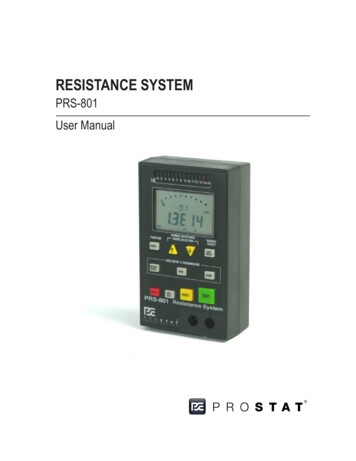
PRS-801 Resistance SystemBattery CompartmentLocated in lower section of case, opposite LCD display. Holds two 9V-transistor batteries. Twoscrews secure the battery cover. Note: Use only Long Life Alkaline Batteries. Remove batterieswhen instrument is not in use for long periods of time.Battery Buss SwitchMUST be off duringbattery change.Figure 3: Opening Battery CompartmentFigure 4: Install 2 each 9V AlkaineBatteriesIV. Battery Installation (See Figures 3 & 4)For optimal battery life and avoid instrument damage, always replace the batteries with high energy,alkaline batteries. Failure to do so will result in a diminished battery life, measurement error and potentialinstrument damage that could void the warranty.The battery caps on the instruments you have purchased are designed to fit snugly. Please follow the directions below for safe replacement of batteries.A. Slide battery bus switch to the OFF position (see figure 3).B. Carefully remove the battery cover from the instrument.C. Gently take the batteries from the battery compartment.D. Unwind any battery lead that is wrapped around the top of the battery terminal. Do not pull battery connection leads - this could cause instrument damage.E. Very carefully place a flat head screwdriver between the battery terminals and gently lift the battery cover from the battery.Rev. D / January 201215
PRS-801 Resistance SystemF. Properly dispose of any old batteries.G. Position the new alkaline battery under the battery cover.H. With your thumb, press the terminals in place one at a time.I. Carefully wind any excess battery lead around the battery terminal below the cap. To avoid instrument damagae, do not pull battery connection leadsJ. Place the batteries back into position with the battery terminal covers facing the lead spurcewithin the battery case shown in figure 4.K. Carefully position the instrument battery cover back into place without force.L. Replace the battery cover screws.M. Slide battery buss switch to the ON position.Following the above directions for battery replacement will insure that you do not damage the batterycovers or wires during this process.NOTEIt is recommended to measure the voltage of each battery with a multimeter. If the voltage ofone battery measures at or below 6.75 volts, replace that battery. If both batteries measure ator below 6.75 volts, replace both batteries.V. Setup & CalibrationA. Setting up the PRS-801 for low resistance range calibration1. Position Battery Buss Cut Off switch to OFF position2. To install batteries, remove two Phillips locking screws and cover. Attach two Long-Life, Alkaline9V batteries to the battery connection terminals.3. Position batteries in compartment with power leads neatly positioned above battery connections. Carefully re-install battery cover and locking screws.NOTEDo Not change batteries with the battery buss ON. Always switch Battery Buss Cut Off to OFFwhen changing batteries. Should the ON/OFF button be depressed during battery change andBattery Bus is ON the instrument may lock up and not function properly or be seriously damaged. In this case, simply disconnect the batteries, then re-install with Battery Buss switch inthe OFF position.B. Low Resistance Range ( 10 Ohms) Calibration1. Install the calibration shunt (PRS-801CC) across the Negative (-) and Positive ( ) Lead Terminals(Figure 5, below).16Rev. D / January 2012
PRS-801 Resistance SystemFigure 5: Low Resistance Range Calibration Shunt Installation2. Press the Red ON/OFF power button. The instrument display should become energized, eachLED will be tested in sequence, and GOOD will is displayed in the LCD if the batteries havesufficient test capacity (figure 10).Figure 6: Low Resistance Range Calibrationusing Reference ModuleFigure 7: Start the Calibration Sequence bypressing RESET then CLEAR within ½ Second3. Allow the instrument circuits to warm-up for a few minutes; approximately 2 - 3 minutes aresufficient, prior to completing the calibration sequence.4. Press MODE once to shift display to ohms mode (Ω).5. Press the Yellow RESET, then the Gray CLEAR button within ½ second. The message CAL will bedisplayed in the LCD. (See Figure 8)6. Press the Yellow RESET button to complete low range (0.1 to 10 ohm) calibration. The CAL message will automatically be cleared when RESET is pressed. (See Figure 8)7. Press the Green TEST button. Indicated resistance should be 1.02 ( 0.02) ohms as shown inRev. D / January 201217
PRS-801 Resistance SystemFigure 8. Press RESET to clear the display. NOTE: If 1.02 ( 0.02) ohms is not displayed, repeatthe calibration process.8. Remove the calibration shunt assembly from the lead terminals9. The PRS-801 is now ready for wide range measurements from 0.1 to 2.0E 14 OhmsFigure 8: Complete Calibration Sequence by Pressing RESET. To confirm Calibration,Press TEST to measure the Calibration Shunt resistance. Shunt resistance should display1.02 Ohms 0.02 OhmsVI. Instrument OperationA. Overview of PRS-801 Operation & Measurement Test Cycle SequenceThe following 10 points provide a general overview for calibrating and using the PRS-801 for resistance measurements.1. Slide Battery Buss Cut Off switch to ON2. Press Red ON/OFF button once to power up PRS-801a. Instrument performs circuit check, and tests LED’s, LCD display, and battery voltage.b. LCD displays GOOD if battery voltage suitable for instrument operation; displays Lo if batteries require replacementc. Instrument ends startup sequence in default AUTO, Exponent Display Mode 1.0EXX3. Select Function Mode if other than AUTO, Exponent Display Mode 1.0EXX is desired by pressing MODE button4. Perform low resistance range calibration after 3 minute instrument warm-up, if desireda. Install Calibration Shunt between positive ( ) and negative (-) terminals18Rev. D / January 2012
PRS-801 Resistance Systemb. Press RESET then CLEAR within ½ secondc. CAL is displayed in LCDd. Press RESET to calibrate instrument to shunt referencee. Press TEST to measure shunt resistance of 1.02 0.02 ohms (Ω)f.Press RESET button to prepare instrument for the next measurementg. Repeat calibration procedure if necessaryh. Remove Calibration Shunt5. Carefully connect test leads to positive ( ) [Power] and negative (-) [Sensing] terminals. Insertright angle sleeved banana into instrument terminal, press gently while twisting into position.a. Standard 10-foot test leads are used for general audit measurements, up to 1.0x10¹² ohmsb. Shielded 42-inch test leads are used for precision applications and bench tests employingspecial fixtures for measurements up to 2.0x10¹⁴ ohms.6. Connect test leads to electrodes, fixture or circuit to be measured7. Press Green TEST button to initiate Automatic measurement Test Cyclea. The resistance range is reset to minimum (0.1Ω). It is automatically adjusted in conjunctionwith the resistance characteristics of the materials under test, based on:(1)Test voltage; and,(2)Current flow.b. Test Voltage is reset to 10V and automatically increased in accordance with the followingmaterial resistance characteristics:(1) 10 Volts: 0.1 to less than 1.0x10⁴ ohms (0.1Ω - 10KΩ)(2)10 Volts: 1.0x10⁴ to less than1.0x106 ohms (10KΩ - 1MΩ)(3)100 Volts: 1.0x10⁶ to 2.0x10¹⁴ ohms (1MΩ - 200TΩ)(4)When OL is displayed, it mean that the resistance is greater than 2.0x10¹⁴ ohmsc. Electrification period, i.e., the time period during which test voltage is applied to the material under test, is automatically adjusted to the PRS-801’s measurement characteristicsand industry standards (ANSI/ESD STM11.11). Typical electrification periods are:(1)2 to 3 Seconds: 0.1 to less than 1.0x10⁴ ohms (0.1Ω - 10KΩ)(2)2 to 4 Seconds: 1.0x10⁴ to less than1.0x106 ohms (10KΩ- 1MΩ)(3)7 to 8 Seconds: 1.0x10⁶ to 1.0x10¹² ohms (1MΩ- 1TΩ)Rev. D / January 201219
PRS-801 Resistance System(4)15 Seconds: 1.0x10¹² to 2.0x10¹⁴ ohms (1TΩ - 200TΩ)8. When the PRS-801 displays and holds the final resistance measurement, HOLD is indicated inthe lower, right corner of the LCD.The PRS-801 is processor controlled to obtain hundreds of measurements per second, andto make rapid adjustments in resistance range and test voltage as necessary. It will displaythe resistance measurement of the material under test based on the following criteria:a. A digital numeric display is the averaged result of eight (8) individual, consecutivemeasurements, each within 5% of each other.b. The display is continuously recalculated and updated during the measurement’s electrification period.c. The final displayed measurement is the averaged result of the last eight (8) individual,consecutive measurements, each within 5%, at the end of the electrification period.d. If the material or test conditions vary such that eight consecutive measurements, eachwithin 5% of each other cannot be obtained, the PRS-801 will extend the electrification period until the measurement criteria are met; or,e. The electrification period will automatically be terminated and the most recent averaged result of eight (8) individual, consecutive measurements will be displayed andheld. NOTE: Several material measurements that vary greater than 15 to 20 percent ofeach other typically indicate inconsistencies in the material or test conditions.9. To save the displayed measurement in the Memory Register and prepare the PRS-801 for thenext measurement, press the Yellow RESET button. Pressing RESET causes three functions:a. Enters (saves) last measurement into Memory RegisterNOTEREC must
A. The PRS-801 Resistance System is battery operated and delivers test voltages up to 100 volts. IMPORTANT: Only use alkaline batteries in the PRS-801. B. The instrument is current limited for safety, however, if improperly used it may be capable of deliv-ering an annoying shock to a person touching conductors energized by the PRS-801 .